University of Huddersfield Repository
Herapath, Colin, Barrans, S M and Weston, W
A Comparison of Design Methodologies for Journal Bearings under Pulsatile Loads
Original Citation
Herapath, Colin, Barrans, S M and Weston, W (2011) A Comparison of Design Methodologies for
Journal Bearings under Pulsatile Loads. In: International Conference on Renewable Energies and
Power Quality (ICREPQ'11), 1315 April 2011, Las Palmas de Gran Canaria, Spain.
This version is available at http://eprints.hud.ac.uk/id/eprint/10215/
The University Repository is a digital collection of the research output of the
University, available on Open Access. Copyright and Moral Rights for the items
on this site are retained by the individual author and/or other copyright owners.
Users may access full items free of charge; copies of full text items generally
can be reproduced, displayed or performed and given to third parties in any
format or medium for personal research or study, educational or notforprofit
purposes without prior permission or charge, provided:
•
The authors, title and full bibliographic details is credited in any copy;
•
A hyperlink and/or URL is included for the original metadata page; and
•
The content is not changed in any way.
For more information, including our policy and submission procedure, please
contact the Repository Team at: [email protected].
A Comparison of Design Methodologies for Journal Bearings under
Pulsatile Loads
C. Herapath
1, S.M.Barrans
1and W.Weston
11
Department of Engineering and Technology
School of Computing and Engineering
University of Huddersfield
Huddersfield HD1 3DH, UK
Mob: +447778 408572, Email: [email protected]
Abstract
The paper expands the work by Kinnear and Weston[1] on squeeze film bearing design to the general case and compares the revised methodology with classical bearing design[2,3,4] and hybrid bearing design[5]. The analysis, which employs a partial differentiation of the Poisseuille and Hagen-Poiseuille bearing flow equations, enables a mathematical model for the bearing squeeze film to be developed. This yields a transfer function between bearing displacement and load. Subsequent parameter maps are developed from the transfer function for stiffness and damping coefficients.The method enables hybrid journal bearings under pulsatile load to be considered. Current design methodologies employed do not cater for this situation adequately which limits effective design of these bearings in applications such as in internal combustion engine crankshaft bearings.
Key words
Hybrid bearings, Squeeze film effect, Power savings, Friction losses, ic engine bearings
1. Introduction
Journal bearings provide a cylindrical bearing face on which the shaft running through the bearing lies. This creates wear between the bearing face and shaft reducing bearing performance and shaft life. To combat this many journal bearings are lubricated to reduce the wear and resistance. Hybrid journal bearings are so named as they combine the features of hydrostatic externally pressurised bearings with those of plain lubricated journal bearings. Three different phenomena provide support for the shaft within the bearing.
Hybrid bearings use orifices to supply fluid under pressure to effectively lift the shaft away from the face when there is zero or low speed operation of the shaft. (figure 1.1)This removes the metal to metal contact normally found in a lubricated journal bearing, reducing wear at start up. However, as the operating speed increases the effectiveness of this phenomenon
is reduced and the pressure at which the lubricant must be supplied increases.
Figure 1.1 Hydrostatic effect
When the shaft is rotating at the operating speed it will rise upon a film of oil as, through viscous drag forces, the shaft creates a film between itself and the bearing face. (figure 1.2) This reduces wear and resistance within the bearing but requires the shaft to be turning at speed to provide adequate support. By combining this effect with the hydrostatic effect at start up a hybrid bearing is able to provide a stiff, smooth bearing with very attractive wear and resistance properties.
The pressurised film generated by the hydrodynamic phenomenon has the effect of damping any motion in the shaft. As the shaft’s speed alters, its position changes within the bearing. Also any change in the loading upon the shaft will move the shaft with respect to the bearing. The pressurised film has the effect of damping this motion generating an effect known as squeeze film damping. This phenomenon has the effect of increasing the bearing stiffness providing improved support for the shaft.
Considerable research into hydrostatic and hydrodynamic effects has been undertaken[5,6,7] but little into squeeze film damping effects[8]. This paper will deal with the situation where a hybrid bearing is subjected to pulsatile loading as would be experienced if the bearing was used on the crankshaft of an internal combustion engine. In this situation the loading would cause the shaft to move relative to the bearing generating a velocity between the two which brings the damping effect into play. It will compare the design methodologies for hybrid journal bearings given pulsating loading in an attempt to increase
understanding of the squeeze film damping effect; its causes and how it can be utilised to improve bearing performance
2. Review and Mathematical Model
Flow will take place within the hybrid bearing in a number of ways. Pressure induced flow causes the lubricant to flow axially and circumferentially between the bearing face and shaft. This is governed by the Poiseuille equation and Kinnear and Weston [1] used this to describe the flow caused by the squeeze film effect and compressibility flow caused by the shaft eccentricity. The squeeze pressure could also cause reverse orifice flow with the pressurised lubricant flowing back along the supply orifices. A fast response non-return valve located in the supply line to stop reverse flow prevents this.
The bearing layout considered is as shown in figure 2 with the land area being equal to the width, Z, multiplied by the length, L. This also shows the axial and
circumferential flow described above.
Figure 2 Dual Hole Entry Hybrid Bearing
The developed Poiseuille equations, used by Kinnear & Weston[1], are applied to the bearing lands to determine the axial and circumferential squeeze flows so:
(
)
2
/
12
2
3L
P
P
ZH
Q
A sq labyη
−
×
=
(i)
(
)
2
/
12
2
3Z
P
P
LH
Q
C sq labyη
−
×
=
(ii
)where:
QA = Axial flow,QC = Circumferential flow,
Z = Bearing width , H = Bearing/Journal Gap L = Bearing length
η = Viscosity (Ns/m2) PSQ = Squeeze pressure (Pa)
PB = Bearing or supply pressure (Pa)
PLABY = Labyrinth pressure (Pa)
The supply(PB) and outlet(PLABY) pressures are neglected,
as they are second order compared with the squeeze pressures. The addition of the partial differential
equations for axial and circumferential flow, equations (i) & (ii), with respect to the two variables present in the
bearing; the gap ’H’ and the squeeze pressure ’PSQ’ yield
the squeeze film flow. The addition of the equations for displaced volume and compressibility flow allows the total flow to be described. This is equated to zero as it is assumed that no return orifice flow takes place because of the installed check valve which yields equation (iii)
dt dp K V dt dh A h P Z LH L ZH p Z LH L ZH e sq
sq / /
3 3 0 2 2 3 3 + + + + + = η η η η
(iii)
where lower case p and h represent perturbations from mean values of P and H.
Equation (iii) is rewritten with the squeeze pressure and gap terms redefined in terms of load and displacement yielding the relationship between shaft load and displacement given by equation (iv)
(
e)
e
w
V
y C
A D
B
D
A
K
+
=
+
(iv)where pSQ= w/AE, h=-y,
B=ZH3/3ηL+LH3/3ηZ and C= (ZH2/ηL +LH2/ηZ)PSQ
This, in turn yields the transfer function described by equation (v) whichallows the bearing stiffness and damping frequency response characteristics to be plotted.
(
)
(
)
01
1
ND
y
K
w
D
τ
τ
+
=
where KO = B/AEC, τN = V/KAE and τD = AE/C
The coefficient, K0, and time constant, τD, allow the
bearing stiffness, k, and bearing damping, CD, to be
plotted for varying squeeze pressures and viscosities respectively.
3. Rationalising Kinnear Weston parameter
maps:
Kinnear and Weston’s paper, [1] developedparameter maps which allowed the bearing stiffness and damping to be determined for varying squeeze pressures and
viscosities. However, these were based upon the bearing dimensions used in the Yamaha YZ 125 research motorcycle engine. To maximise the use of their work to the engine designer the equations governing the bearing stiffness and damping need to be normalised to remove the effect of bearing size.The previous work already had a term for the effective area of the bearing land, AE,
defined as the length multiplied by Z, equal to the diameter.
Now a new term is introduced, aspect ratio, RA similar to
that used in compressor design. This is defined as: RA = Z/L
and allows normalisation of equations (i) and (ii) and subsequently the parameter maps (figures 3.1 and 3.2)
3 3 2 2
2 2
0
12 / 2 12 / 2
A A
SQ SQ E SQ
A A
R H H R H H V
P P h A h P
R R K
η η η η
= + + + + +
& &
(viii)
which will yield the transfer function as described in section 2.
For parameter mapping, stiffness, k, is defined as 1/K0 or
AEC/B. Damping is defined from τD = cD/k which yields
cD = kAE/B. The new functions now allow the equations
for stiffness and damping to be written as:
(
)
(
)
2 31/
1/
3
EA A SQ
A A
A H
R
R
P
k
H
R
R
η
η
+
=
+
(ix)
(
)
2 33
1/
E D A AA
C
H
R
R
η
=
+
(x)
These simplify to form the equations:
3
ESQ
A
k
P
H
=
(xi)
(
)
2 33
1/
E D A AA
C
H
R
R
η
=
+
(xii)
Substituting the expression for bearing aspect ratio RA
into (i) and (ii) yields equations (vi) and (vii) which describe axial and circumferential flows as a function of the newly described bearing aspect ratio.
3
2
12 / 2
A
A SQ
R H
Q
P
η
=
(vi)
3
2
12
/ 2
C SQ A
H
Q
P
R
η
=
(vii)
Carrying out the partial differentiation to these equations with respect to the same variables, supply pressure and 1bearing gap, yields the following modification to equation (iii).
With these equations values of k/AE can be plotted
against bearing gap H for varying squeeze pressures and values of (RA + 1/RA)cD/AE2 can be plotted against h for
varying viscosities.
This yields the theoretical stiffness and damping for any size hybrid bearing conforming to the same construction and could be used by the bearing designer to estimate the bearing performance regardless of the size used. Figures 3.1 and 3.2 show the bearing parameter maps.
[image:4.595.133.445.571.727.2]
Figure 3.2 Graph showing bearing damping against bearing gap
Label ‘A’ indicates the bearing design point referring to the proposed hybrid bearing design for the research engine.The load locus is included by way of an example of the parameter maps use. X axis variations indicate bearing clearance variations due to the pulsating load. The bearing is designed with 0.025mm gap. At this point the eccentricity is 0. However, the shaft can move within the bearing to create a gap of 0.0125mm if with an eccentricity ratio ε = 0.5. This will move the locus to B Note ε = e/H where e = shaft eccentricity and H = bearing clearance. Vertical load locus variations indicate
performance variations with squeeze pressure and viscosity changes as indicated by labels ‘C’. This technique allows the bearing designer to specify the stiffness and damping characteristics required and to design the bearing with these desired characteristics.
4. Comparison of design methodologies
Revision of the Weston Kinnear design methodology is compared against traditional design methodologies [2,3,4] and hybrid bearing design[5].
The methodology described in the BP publication ‘Lubrication Theory and its Application’[4] is based on the work of Michell[9] in 1929 and extended by Ocvirk and Dubois[10] in 1953. It defines the bearing parameters of ‘short’ bearings where the ratio of bearing length to diameter is 1 or less. The circumferential pressure
distribution within the bearing is estimated and then the external bearing load is related to these pressures induced which, in turn, allow the load capacity of the bearing to be calculated.
Ocvrik and Dubois’ work centred on extending the Sommerfield Number, SN, which relates the clearance
ratio h to the viscosity, speed and load. They introduced a length to diameter ratio, L/D, to create what is defined as the bearing Capacity Number CN . Equation (xiii)
defines CN in terms of Summerfield Number SN. 2
N N
L
C
S
D
=
(xiii) Reference [4] explains that it is of more use to plot the reciprocal, 1/CN, which is named the Load Number. TheLoad Number is non-dimensional and is described in the following manner in terms of the eccentricity ratio ε.
(
)
(
)
1/2
2 2 2
2 2
1
1 16
1
N
C
πε
π
ε
ε
ε
= − +
−
(xiv)
The bearing designer is now able to use a series of curves to plot Load Number (1/CN) against performance
parameters such as the eccentricity ratio of the bearing.
Figure 4 shows eccentricity ratio vs load number.
The purpose is now to alter the factors affecting CN
where possible so that the minimum film thickness is maintained to a sufficient level under normal operating conditions.
The methodology described by W. B. Rowe is very extensive and covers all factors affecting the possible performance of the hybrid bearing. This method defines the bearing size required for a given load. The value of the load that able to be supported is described as very strongly dependent upon the Power Ratio K. This is the ratio between the frictional power and the pumping power. The Power Ratio is used extensively to describe the operation of the bearing and it allows the proportion of hydrostatic and hydrodynamic effects to be calculated. Where K= 0 the bearing is relying purely on the
hydrostatic effect, i.e. there is no rotation. When K= 3 the load contributions of the two effects are of the same magnitude.
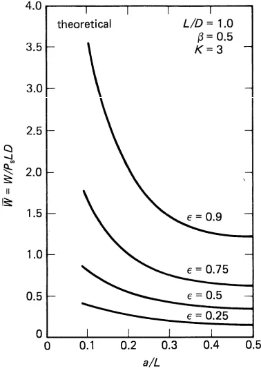
[image:6.595.312.493.246.516.2] [image:6.595.98.287.249.516.2]For hybrid design Rowe recommends the Power Ratio range to be 3 ≤ K ≤ 9. The load capacity at K= 3 will be lower than that where K=9 so the maximum permissible load that the bearing should carry is given when K=3. The bearing designer now consults the design curves that will determine the load parameter possible. These are shown in figures 4.2a and 4.2b.
Figure 4.2a shows the load capacity when K= 3. Figure 4.2b is shown to illustrate the increase in load capacity if the bearing is designed with Power Ratios outside the recommended range, in this case, K=12.
Figure 4.2a Design chart[5] with K=3 Figure 4.2b Design chart[5] with K=12
The formulae controlling bearing performance in this method requires the eccentricity to be estimated and there is no mechanism for fluctuating eccentricity due to pulsatile loads to be considered. The charts also show the effect of the land ratio, a/L, on the capacity. This is the ratio between the bearing length and the distance between the bearing edge and feed capillaries. Single entry bearings will have a land ratio of 0.5, which shows how their capacity is lower than that of the double entry bearings. The data in the top right shows that these charts are only true for an aspect ratio of 1, and have not been normalised as described in this paper.
The revised Weston Kinnear method describes how the effect of a pulsatile load can be considered in the bearing design process. The traditional methodology does consider dynamic loading but only constant cyclical loading such as shaft out-of-balance and accepts that the method described only works when the designer
considers the eccentricity over a period of time. The designer thus carries out the calculations with the initial
conditions and then recalculates the parameters for other expected conditions using small increments because the movement of the shaft is related to its starting position. Dynamical loading is not considered in hybrid bearing design[5] and the method enables load capacity to be calculated as long as bearing eccentricity is known and constant.
This is in contrast to the partial differential of the squeeze pressure and bearing gap or eccentricity, described in the Weston Kinnear [1] method which allows for dynamical loading to be considered.
5. Conclusions
and therefore load capacity, at any point in time for any load. Both the Weston Kinnear method and the two other methods considered the bearing load carrying capacity is related to the shaft eccentricity. This causes an issue with the prediction of bearing performance when subjected to a dynamic load because the position of the shaft is directly related to the preceding load history, not just the magnitude of the load at any given instant. This method only suggests solving the equations at small steps to build a locus of shaft position over time.
Hybrid design methodology does not allow for the effect of a pulsatile load to be predicted whereas the method proposed by Weston Kinnear enables dynamical loading to be considered. The bearing stiffness can be obtained
for any given shaft eccentricity and, therefore, the load capacity can be calculated independently of the loading effects on the shaft position time history.
The method requires experimental validation to define the limits of bearing geometry for the parameter maps to remain accurate. The refined design methodology, as a result, will enable designers to specify hybrid journal bearings in place of traditional rolling element bearings in applications such as an internal combustion engine crankshaft bearing where a pulsatile load must be supported. The elimination of metal-to-metal contact within the hybrid bearing reduces rotational friction therefore reducing the power lost in the bearing.
.References:
[1] Kinnear, D. and Weston, W. ‘’A Design Methodology for
the Prediction and Measurement of Squeeze Film Stiffness and Damping in Hybrid Journal Bearings under Pulsatile Load Conditions’’. 10th Int .Conf. on Renewable Energy and Power Quality, Granada(Spain), March2010.
[2] Schlichting,K. & Gerston,K.’’Boundary Layer
Theory’’,8th edition 2009, Springer, ISBN 3-540-66270-7.
[3] Hamrock,R.J.,Schmid,S.R. & Jacobson,B.O. ‘’Fundamentals of Fluid Film Lubrication’’, Marcel Dekkar
Inc., ISBN 0-8247-5371-2
[4]BP Publication, Lubrication Theory and its
Application, BP Trading Limited, London, 1969.
[5]Rowe,W.B.,‘’Hydrostatic Bearing
Design’’Butterworths, ISBN 0-408-01324-9.
[5]Rowe,W.B.,Xu,S.X., Chong,F.S. and Weston,W.,
’’Hybrid Journal Bearings with particular reference to hole entry configurations’’, Tribology International. Vol.15, pp339-48.
[6]Koshal,D. and Rowe,W.B., ‘’Fluid Film Journal
Bearings operating in a Hybrid Mode: PartI – Theoretical Analysis and Design’’, Journal of Lubrication
Technology, ASME, Vol.103,pp558 – 65, October 1981.
[7]Koshal,D. and Rowe,W.B., ‘’Fluid Film Journal
Bearings operating in a Hybrid Mode: PartII – Experimental Investigation’’ Journal of Lubrication Technology, ASME, Vol.103,pp565-72, October 1981.
[8]Rowe,W.B., Weston,W. And Koshal,,D., ‘’Static and
Dynamic properties of Concentric Hybrid Journal Bearings by Small Displacement Analysis’’, Euromech Conference on Hydrodynamic Lubrication of Bearings, Fiat, Turin, Oct. 1979.
[9]Michell,A.G.M., Transactions ASME, Sept. –
Dec.1929, pp153 – 163.
[10]Dubois,G.B. and Ocvirk,F.W., ‘’Analytical