2018 International Conference on Modeling, Simulation and Optimization (MSO 2018) ISBN: 978-1-60595-542-1
Theoretical Research on Ultimate Strength of Dual-angle Cross
Combined Section Under Eccentric Compression
Hao HU
*School of Civil Engineering, Chongqing University of Arts and Sciences, Chongqing, China *Corresponding author
Keywords: Double-angle, Combined section, Theoretical research.
Abstract. A total of 12 Q420 dual-angle cross combined section columns were tested under various eccentric compression with either single or double internode. The specimen parameters, experimental setup, and test results are presented. It showed that overall bending buckling appeared for specimens. Based on tests, the theoretical formulas on stability factor were derived by the energy approach. It is shown the ultimate strength from theoretical formulas are basically identical with experiments results.
Introduction
The transmission tower structures with high-strength combined angle section are widely applied in electric power project, while research on behaviors of dual-angle cross section is obtained rarely. Earls [1-3] studied equal-leg single angle geometric axis flexure and proposed relevant calculation methods by finite element techniques which compared and were agreed well with test results. The response of steel single equal-leg and unequal-leg angles subjected to eccentric compression were investigated by finite element analysis and experimental study by Liu [4-5]. Liu studied dual-angle cross combined section columns of single internode under axial compression by test, and derived theoretical formulas on capacity based on the energy approach [6]. Calculation method of pad connecting two angle steel in transmission steel tower was obtained by Zhong [7].
Overall, in order to better understand the characteristics of dual-angle cross combined section columns, this research involved a testing of 12 specimens under various eccentric compression with either single or double internode. Finally, the theoretical formulas using the energy approach based on test results were given, which were consistent with experiments basically.
Experimental Work Test Specimens
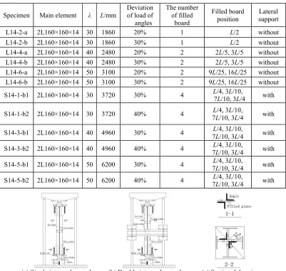
Table 1. The test specimens of dual-angle cross combined section.
Specimen Main element λ L/mm
Deviation of load of angles
The number of filled
board
Filled board position
Lateral support
L14-2-a 2L160×160×14 30 1860 20% 1 L/2 without L14-2-b 2L160×160×14 30 1860 30% 1 L/2 without L14-4-a 2L160×160×14 40 2480 20% 2 2L/5, 3L/5 without L14-4-b 2L160×160×14 40 2480 30% 2 2L/5, 3L/5 without L14-6-a 2L160×160×14 50 3100 20% 2 9L/25, 16L/25 without L14-6-b 2L160×160×14 50 3100 30% 2 9L/25, 16L/25 without
S14-1-b1 2L160×160×14 30 3720 30% 4 L7/4, 3L/10, 3L/10, L/4 with
S14-1-b2 2L160×160×14 30 3720 40% 4 7LL/4, 3/10, 3L/10, L/4 with
S14-3-b1 2L160×160×14 40 4960 30% 4 7LL/4, 3/10, 3L/10, L/4 with
S14-3-b2 2L160×160×14 40 4960 40% 4 7LL/4, 3/10, 3L/10, L/4 with
S14-5-b1 2L160×160×14 50 6200 30% 4 7LL/4, 3/10, 3L/10, L/4 with
S14-5-b2 2L160×160×14 50 6200 40% 4 7LL/4, 3/10, 3L/10, L/4 with
[image:2.612.107.512.80.466.2]
(a) Single internode member (b) Double internode member (c) Sectional drawings Figure 1. Shape of the specimen and test setup.
Test Setup and Result
The specimens were loaded vertically by a testing machine, in Figure 1. The specimen ends were bolted by shoe planks which were connected with hinge caps. The hinge support was consisted of the hinge cap and ball hinge which was joined by the base. The lateral supports of the double internode specimens were connected with cross beams which were combined by the loaded frame. A theodolite was used to measure the verticality of the specimen before test. The load shortening and lateral displacement were recorded by using the Tokyo-Sokk S-2420 data acquisition system.
The failure mode was overall bending buckling on the specimens of L14 series which were single internode eccentric compression members. Bending buckling in every internode appeared on S14 series specimens which were double internode eccentric compression members, and no torsional buckling occurred.
The Theorical Model
by dxdy y w p dxdy y x w y w x w y w x w D
II a b a b x 2
0 0 0 0 2 2 2 2 2 2 2 2 2 2 2 ) ( 2 1 ) ( ) 1 ( 2 ) ( 2
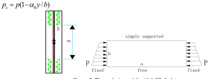
(1)The Number of the Filled Plate is 1 under Eccentric Compression
When the amount of the filled plate is equal to 1 in Figure 2, the deflection surface function of plate w, which is consistent with the geometric and mechanical boundary conditions,is assumed as
) 2 cos 1 ( x a m fy
w (2)
Under pressure and bending moment, px is the line load distributed on the surface of plate, and α0 is the stress gradient in Figure 2 and 3.
0
(1
/ )
x
p
p
y b
(3) [image:3.612.92.462.257.391.2]
Figure 2. The analysis model with 1 filled plate.
Substituting Eqs. (3) and (2) into Eq.(1), the total potential energy (II) is given by
2 2 3 2 2 2 2
2 2 3
0
2 2
4
2
(1
)
1
4
1 1
2
3
3
3 4
D
m
b m
m
II
f
ab
pf
ab
a
a
a
(4)According todII 0
df and f≠0, it can be given by
)
4
3
1
/(
)
1
(
2
3
4
0 2 2 2 2 2 2
a
m
b
b
D
p
(5)The buckling load of the plate can be obtained when m=1 and ν=0.3.
)
4
3
1
/(
4
.
1
3
4
0 2 2 2 2 2
a
b
b
D
p
cr (6)For the not too thin angle plate, the buckling will occur in the elastic-plastic state when the buckling stress obtained from the elastic buckling formula exceeds the material proportional limit.
2 2
1 2 2 2 0
4
1.4
1 1
(
)/
3
3 4
cr
D
b
p
b
a
,
1
E E
t/
(7)2 2
2 2 2 2 0
4
1.4
1 1
(
)/
3
3 4
cr
D
b
p
b
a
,2 2
2
0.1013 (1 0.0248
f E f E
y/ ) /
y
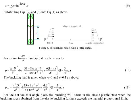
(8)The Number of the Filled Plate is 2 under Eccentric Compression
When the amount of the filled plate is equal to 2 in Figure 3, according to boundary conditions of plate, the deflection surface function of plate w can be assumed as
2 sin m
w fyx x
a
(9) Substituting Eqs. (9) and (3) into Eq.(1) as above.
[image:4.612.78.534.159.506.2]
Figure 3. The analysis model with 2 filled plates.
According todII 0
df and f≠0, it can be given by
2 2 2 2
2
0
2 2 2 2 2
33 8 6(1 ) 3
4 /(1 )
3 8 4
D m b
p m
b m a
(10)
The buckling load is given when m=1 and ν=0.3 as above.
2 2 2
0
2 2 2 2
33 8 4.2 3
4 /(1 )
3 8 4
cr
D b
p
b a
(11)
For the not too thin angle plate, the buckling will occur in the elastic-plastic state when the buckling stress obtained from the elastic buckling formula exceeds the material proportional limit.
2 2 2
1 2 2 2 2 0
33 8 4.2 3
4 /(1 )
3 8 4
cr
D b
p
b a
, 1 E Et/ (12)
When the plate occurs local buckling, the buckling load is given as above.
2 2 2
2 2 2 2 2 0
33 8 4.2 3
4 /(1 )
3 8 4
cr
D b
p
b a
,
2 2
2 0.1013 (1 0.0248 f E f Ey/ ) /y
30 35 40 45 50 0.5
0.6 0.7 0.8 0.9 1.0
Experiment(20%) Theory(20%) Experiment(30%) Theory(30%)
30 35 40 45 50
0.5 0.6 0.7 0.8 0.9 1.0
Experiment(30%) Theory(30%) Experiment(40%) Theory(40%)
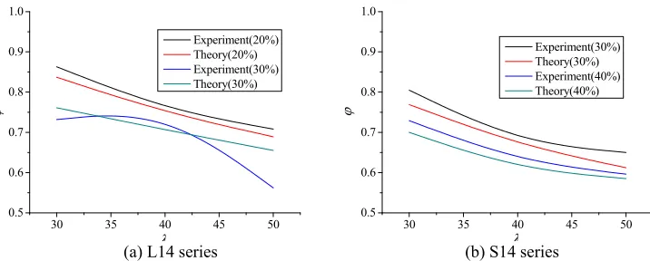
[image:5.612.118.476.67.211.2](a) L14 series (b) S14 series Figure 4. Comparison of stability factor obtained from test and theory.
The stability factors obtained from the theory calculation and tests are compared in Figure 4 for all specimens [8]. The theoretical value is lower than that of the test mainly owing to two hypothesis of calculation model. The one is that the effect of constraint from the filled plate to angle on bearing capacity of specimens is ignored. The other is that the impact from steel hardening on the carrying capacity is not taken into consideration in the theoretical analysis. However, it can be seen that the change trend is basically consistent with each other.
Summary
In this test, the specimens were L160×14 and the material was Q420, which included single and double internode components under eccentric compression. Based on the experimental and theoretical results, the conclusions are as follows:
(1) The failure mode is overall bending buckling around the strong axis of cross combined section rather than torsional buckling. Bending buckling on double internode members appears in every internode and the internode deformation is more apparent near the loading end.
(2) The theoretical formula of dual-angle cross combined section under compression derived shows that it is not only effected by limb wide and thickness of angle iron but also the number of filled plate. It is shown from the comparison that the component strengths calculated using the theoretical equations were agreed well with the test results, which simplified complex stress state of members and can provide theoretical basis for practical engineering.
Acknowledgement
This research was financially supported by the science and technology project of Chongqing University of Arts and Sciences (No.2017RJJ31).
References
[1] C.J. Earls, T.V. Galambos, Design recommendations for single angle flexural members, J. Constr. Steel Res. 43 (1-3) (1997) 65-85.
[2] C.J. Earls, Single angle geometric axis flexure, I: Background and model verification, J. Constr. Steel Res. 57 (2001) 603-622.
[3] C.J. Earls, Single angle geometric axis flexure, II: Design recommendations, J. Constr. Steel Res. 57 (2001) 623-646.
[4] Y. Liu, L.B. Hui, Finite element study of steel single angle beam-columns, Eng. Struct. 32 (2010) 2087-2095.
[6] H.J. Liu, Z.L. Li, Study of ultimate strength of dual-angle cross combined section of high-strength steel, Eng. Mech. 30 (1) (2013) 140-146.
[7] Y.H. Zhong, X.H. Jin, Calculational method of pad connecting two angle steel in transmission steel tower, Guangdong Elec. Power. 21 (3) (2008) 37-39.