HP 9000 Series 500 Computer Systems
HP 27123A
Programmable Serial Interface
Shared Resource Management System (PSI SRM)
Installation Manual
Hewlett-Packard Company Roseville Networks Division
8000 Foothills Boulevard Roseville, California 95678
Flin-
HEWLETT
a:~
PACKARD
Card Assembly: 27123-60001 Date Code: B-2529
Manual Part Number 27123 - 9 0001 E0985 Printed in U. S. A.
PRINTING HISTORY
The Printing History below identifies the Edition of this Manual and any Updates that are included. Periodically, update packages are distributed which contain replacement pages to be merged into the manual, including an updated copy of this Printing History page. Also, the update may contain write-in instructions.
Each reprinting of this manual will incorporate all past updates; however, no new information will be added. Thus, the reprinted copy will be identical in content to prior printings of the same edition with the user-inserted update information. New editions of this manual will contain new information, as well as updates.
First Edition. . Second Edition.
27123-90001
NOTICE
. . August 1983 . September 1985
The information contained in this document is subject to change without notice.
HEWLETT-PACKARD MAKES NO WARRANTY OF ANY KIND WITH REGARD TO THIS MATERIAL, INCLUDING, BUT NOT LIMITED TO, THE IMPLIED WARRANTIES OF MERCHANTABILITY AND FITNESS FOR A PARTICULAR PURPOSE. Hewlett-Packard shall not be liable for errors contained herein or for incidental or consequential damages in connection with the furnishing, performance or use of this material.
This document contains proprietary information which is protected by copyright. All rights are reserved. No part of this document may be photocopied, reproduced or translated to another language without the prior written consent of Hewlett-Packard Company.
SAFETY CONSIDERA TIONS
GENERAL - This product and related documentation must be reviewed for familiarization with safety markings and instructions before operation.
SAFETY SYMBOLS
Instruction manual symbol: the product will be marked with this symbol when it is necessary for the user to refer to the instruction manual in order to protect the product against damage.
Indicates hazardous voltages.
Indicates earth (ground) terminal (sometimes used In manual to indicate circuit common connected to grounded chassis).
The WARNING sign denotes a hazard. It calls ~!ttention to a procedure, pl'actice, 0r the like, which, if not correctly performed or adhered to, could result in injury, Do not proceed beyond a WARNING sign until the indicated conditions are fully understood and met.
I
CAUTIONI
The CAUTION sIgn denotes a hazard. It calls attention to an operating proced ure, practice, or Lhe like, which, if not correctly perf ormed or adhered to, could result in damage to or destruction of part or all of the product. Do not proceed beyond a CAUTION sign until the indicated conditions are fully understood and met.CAUTION
ST A TIC SENSITIVE DEVICES
When any two materials make contact, their surfaces are crushed on the atomic level and electrons pass back and forth between the objects. On separation, one surface comes away with excess electrons (negatively charged) while the other is electron deficient (positively charged). The level of charge that is developed depends on the type of material. Insulators can easily build up charges in excess of 20,000 volts. A person working at a bench or walking acroSs a floor can build up a charge of many thousands of volts. The amount of static voltage developed depends on the rate of generation of the charge and the capacitance of the body holding the charge.
If the discharge happens to go through a semiconductor device and the transient current pulse is nut effectively diverted by protection circuitry, the resulting current flow through the device can raise the temperature of internal junctions to their melting points. MOS structures are also susceptible to dielectric damage due to high fields.
The resulting damage can range from complete destruction to latent degradation.
Small geometry semiconductor devices are especially susceptible to damage by static discharge.
The PSI SRM card is shipped in a transparent static shielding bag. The card should be kept in this bag at all times until it is installed in the system. Sa ve this bag
f or storing or transporting the card. When installing the card in the system, do not touch any components. Hold the card only by the edges or extractor levers.
:WARNING
SAFETY
EARTH
GROUND - The computer on which this product is installed is a safety class I product and is provided with a protective earthing terminal. An un interruptible safety ground must be provided from the main source to the product input wiring terminals, power cord, or supplied power cord set. Whenever it is likely that the protection has been impaired, the product must be made inoperative and must be secured against any unintended operation.SERVICING
'WARNING
This manual provides information for you to install and verify correct operation of the HP 27123A Programmable Serial Interface Shared Resource Management (PSI SRM) card. You will also need the appropriate computer system installation manual. These two manuals should provide all the required information.
INST
ALL A
TION
Before installation review the safety precautions in the front of this manual. Install the PSI SRM as follows:
1. Determine if your computer system can supply the power needed for the PSI SRM card. Refer to table 1 for power requirements for the PSI SRM card. If the PSI SRM card is going to provide power for the HP 98028A Resource Management Multiplexer, refer to the appropriate manual for power requirements for this item. The PSI SRM card can provide power for a maximum of two HP 98028A m ul tiplexers.
Ta ble 1. Power Requirements for the PSI SRM Card.
Current (Amps) Power Dissipation (Watts) Voltage (typical) (2-sigma) (typical) (2-sigma)
+ 5 V 1.415 A 1.616A 7.077 W 8.082 W +12 V 0.072 A 0.087 A 0.864 W 1. 040 W -12 V 0.094 A 0.109 A 1. 128 W 1. 304 W
-Total Power Consumption: 9.069 W 10.426 W
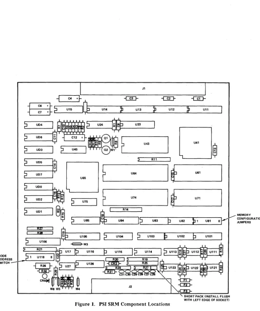
2. Verify that the Memory Configuration jumpers (U 81, see figure 1) are configured correctly for the EPROMs/RAMs installed on the card. For the PSI SRM card, jumpers should be installed in jumper positions 2, 4, and 5. Jumpers should not be installed in any of the other jumper positions.
3. The Node Address switch (SW 1 through SW 8) at location U 118 (see figure 1) is used to set the node address for the PSI SRM card.
The setting on this switch must correspond to the node address assigned to you by your System Manager. See table 2 for information on setting the switches to obtain the desired address.
S. Install the card in the appropriate slot in the computer. When installing the card, use care not to damage components or traces on the card or on adjacent cards. Press the PSI SRM card firmly into place.
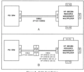
6. If the PSI SRM card is to provide power to the HP 98028A Resource Management Multiplexer, connect the 2-foot cable (part number 27123-63002, supplied with the card) from J2 on the PSI SRM card to the SO-pin connector on the multiplexer (see figure 2A). If the PSI SRM card is not going to provide power to the multiplexer, connect the 2-foot cable (part number 27123-63002) to pin J2 on the PSI SRM card, then connect cable HP 97061A (10-meter), HP 97061B (25-rneter), HP 97061C (60-meter), or HP97061D (60-meter cable and connector kit) from cable 27123-63002 to one of the 15-pin connectors on the multiplexer (see figure 2B). If you have the test hood, which exercises more of the card's circuitry, and can be ordered separately (Hewlett-Packard part numher 1258-0207), connect it to J2 instead of connecting the cable.
CAUTION
Be sure to install the diagnostic test hood so that its component side (the side with the LED) has the same orientation as the component side on the PSI SRM card. Damage to the PSI SRM card can result if the test hood is installed incorrectly.
NOTE
A IIgrounding grommetll
on the interface cable allows the cable shield to be grounded at that point in some applications. Models 520, 530, and 540 do not use this grommet. Your computer installation manual will have details.
7. Turn on computer system power.
8. A self -test is contained on the card. The host computer system determines if the self -test is run automatically at power-on or must be invoked by the user. Refer to the appropriate manual for your system for a description of self ·-test initiation .
• If the di3.gnostic test hood is not installed when the self -test executes. the LED located on the card should light briefly and go out. This indicates that the card passed self -test. If the LED does not light at all, the card is defective. If the LED stays on, the card did not pass self -test. For either of these latter two cases, return the card to Hewlett-Packard (refer to the IIReshipment" paragraph for details) .
• If the diagnostic test hood is installed when the self -test executes, the conditions above should occur, plus the LED located on the test hood should light briefly and go out simultaneously with the card's LED. If the LEOs (the one mounted on the card and the one mounted on the diagnostic test hood) do not light at all, or if they light and stay on, the causes are the same as above.
J1
+~ -@J- -@J-
-UIJ-I~
U14»
U13~
U12»
U11i
C4ffi2
U15U24 U23
2
U041
S
~ ~11tlI~IMblr..1
' - - - 12
U06®
2
UD32
U45U41 U43
®
' - - - '
~ R11
U65
E
'----
_ U 6 4 _ 1~_U61---,
r
-2
U--'75IP
~
:::::;:;;=:::::U74~I
t _ U 7 1 - - - - I~
~ _ _ R1_4,::::::JMEMORY
r-:--
U-S-5 - ... 11
(j
---'"II
r-C;----"T"h---nq:;---. ~ CONFIGURATION CL-_ _ _ _ ...". _ U84 L-r' _ _ U_S3_--Jtl..-.._U_S_2_...IIJt-lL--1 _ _ US_1 _ _ S...,,!I
JUMPERSI
2
U104I
~,-
__
U1_03_-.lL~
_ _ U_10_2_...Lp _ _ U_10_1----1R27
~
I - - - I .R_2I"-,=:::J en
r - - - , (j U105
L..2 _ _ U_1_06 _ _ ...,,1
~W3
P
U11512
U"412
U113®.-t---I
NODE L, 1 U11S •
ADDRESS r' ~_---'[::;----;::;::---'I' ~
Me
I ~C""---:=-=--"'IM
R21U116
~ C - -'~2S d (.) U123 ...
-{]lD- ~
-t:!hlF
Oe:> ~ Ot----wIU ... ---{~SWITCH
~
---G26l-~C;::'''':U~7:....J11~I-o.--_U_126_---, ~
_o
a: C31 C30 CCR.~
•W
J2 ' : ]W6 W5 W4
Figure 1. PSI SRM Component Locations
SHORT PACK (INSTALL FLUSH WITH LEFT EDGE OF SOCKET)
[image:7.617.58.592.71.708.2]RESHIPMENT
Ii the PSI SRM is to be reshipped to Hewlett-Packard for any reason, attach a tag identifying the owner and indicating the reason for shipment. Include the part number of the PSI SRM.
Remove and retain the EPROM. The I/O chip and microprocessor should stay on the card.
Pack the card in the original factory packing material, if available. If the original material is not available, good commercial packing material should be used. Reliable commercial packing and shipping companies have the facilities and materials to repack the item. BE SURE TO OBSERVE ANTI-STATIC PRECAUTIONS.
PRODUCT HISTORY
In order for you to better understand where the current card fits into the PSI SRM framework, this section will briefly cover the product history. It may be helpful to look at the Printing History found on page ii.
The product 1irst appeared in August of 1983. Essentially unchanged, it underwent a minor revision to a connecting cable (part number 8120-4269) in late 1984. This change involved the addition of a grounding grommet to reduce Radio Frequency Interference radiated by the cable in certain computer applications. The grounded cable is part number 27123-63001. This cable works in models 520, 530, and 540, but it is not mandatory, while all other models require the new cable for proper function.
To further increase its usefulness, Hewlett -Packard revised the cable in 1985. The new cable is part number 27123-63002. It is required for connecting the PSI SRM to the new SRM coaxial network, and is fully backwards compatible. There was an accompanying firmware change (part number 27123-80001 was replaced by 27123-81001). The new EPROM code is fully backwards compatible, and is required for use in the SRM coaxial network.
PSI SRM
PSI SRM
z
i:i:
I
CABLE :is
27123-63002
A
z z z
t========l
~ oif
0 F======1 ~ lI')CABLE I() I.() CABLE
27123-63002 HP 97061A (10 M)
B
HP 97061 B (25 M)
HP 97061 C (60 M)or HP 97061 D (60 M)
Figure 2. Cable Installation
15-PIN
HP ga028A RESOURCE MANAGEMENT MULnPLEXER
15-PIN
HP 98028A
RESOURCE MANAGEMENT MULnPLEXER
15-PIN
Table 2. Node Address Switch Settings U118
MSB LSB NODE
SI S2 S3 S4 S5 S6 S7 S8 ADDRESS
NOT 0 0 0 0 0 0 0
USED 0 0 0 0 0 1 1
0 0 0 0 1 0 2 0 0 0 0 1 1 3 0 0 0 1 0 0 4
.,
1 1 1 1 0 1 61 1 1 1 1 1 0 62 1 1 1 1 1 1 63
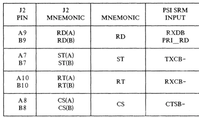
[image:9.612.130.481.66.703.2] [image:9.612.134.484.70.372.2]Table 3. Inputs from the Resource Management Multiplexer to the PSI SRM Card
J2 J2 PSI SRM
PIN MNEMONIC MNEMONIC INPUT
A9 RD(A)
RD RXDB
B9 RD(B) PRI - RD
A7 ST(A)
ST
TXCB-B7 ST(B)
AID RT(A)
RT
RXCB-BID RT(B)
A8 CS(A)
CS
CTSB-B8 CS(B)
Table 4. Outputs from the PSI SRM Card to a Peripheral Device
-J2 J2
MNEMONIC PSI SRM
PIN MNEMONIC OUTPUT
A4 SD(A)
SD TXDB
B4 SD(B)
A6 TT(A)
TT ST
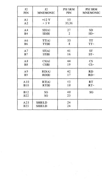
[image:10.618.148.470.97.286.2] [image:10.618.145.479.353.465.2]Table 5. Cable Connections
12 12 PSI SRM PSI SRM PIN MNEMONIC PIN MNEMONIC
Al +12 V 10
A2 +5V 35,36
A4 SD(A) 27 SD
B4
SD(B) 2SD-A6 TT(A) 33 TT
B6 TT(B) 8
TT-A7 ST(A) 41 ST
B7 ST(B) 16
ST-A8 CS(A) 44 CS
B8 CS(B) 19
cs-A9 RD(A) 42 RD
B9 RD(B) 17
RD-AIO RT(A) 43 RT
BIO RT(B) 18
RT-Bl2 SG 48 SG
B22 SG 23
A25 SHIELD 24
B25 SHIELD 24
[image:11.617.104.462.82.719.2]READER COMMENT SHEET
UP 9000 500 Series Computer Systems
UP 27123 PROGRAMMABLE SERIAL INTERFACE SHARED RESOURCE MANAGEMENT SYSTEM Installation Manaual
27123-90001 September 1985
We welcome your evaluation of this manual. Your comments and suggestions help us to improve our publications. Please explain your answers under Comments, below, and use additional pages if necessary.
Is.this manual technically accurate?
Are the concepts and wording easy to understand?
Is the format of this manual convenient in size, arrangement, and readability? Comments:
DYes D No DYes D No DYes D No
This form requires no postage stamp if mailed in the U. S. For locations outside the U. S., your local HP representative will ensure that your comments are forwarded.
FROM: Date
Name
Company
FOLD
FOLD
111111
," ' . . r ; . . : , ....
BUSINESS REPL V MAIL
FIRST CLASS
PERMIT NO. 256 ROSEVILLE, CALIFORNIA
POSTAGE WILL BE PAID BY ADDRESSEE
Publications Manager, Marketing
HEWLETT-PACKARD COMPANY
Roseville Networks Division
8000 Foothills Boulevard
Roseville, CA 95678-6598
FOLD
NO POSTAGE
NECESSARY
IF HAILED
IN THE
UNITED STATES
r!JiJI
HEWLETT
r1:~
PACKARD