2016 3rd International Conference on Information and Communication Technology for Education (ICTE 2016) ISBN: 978-1-60595-372-4
1 GENERAL INSTRUCTIONS
Oil pan is a special feature piece on the car, which has more complex shapes and tight dimensional and geometric tolerances. The application of multi-position progressive die stamping implement technology punched a complex shape, high dimensional and geometric accuracy, consistency and interchangeability strong, lightweight structural parts can not be processed by other processing methods, the industry is heavily promoted stamping technology.
"Mold surface driven" finite element simulation technology, advanced design methods of modern automotive panel die design representative. "Mold surface drive" means elastoplastic large deformation finite element simulation analysis software and related technology, three-dimensional digital-analog body panels, press fabric, "die die face" that tool addendum constituted, be upfront simulation and optimization, to get as far as possible to eliminate the "best" drawing die face deep drawing and other "defects" of. "Mold surface driven" finite element simulation technology is to implement multi-station stamping of key technologies.
Based on the above background, this paper AutoForm Engineering Co., Ltd. design and development of sheet metal forming simulation software, the establishment of multi-station sump stamping simulation model, simulation model created to meet the design requirements. Through
the implementation of the oil base and multi-station transfer mold, to achieve a high-speed automated stamping parts, stamping stable quality, greatly improving production efficiency. Parts for the deep-drawing mold development and technical personnel to solve the technical problems faced and provide regular guidance.
2 RESEARCH ARTICLE
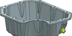
[image:1.612.360.507.658.733.2]In this paper, parts for a car engine oil pan. Figure 1 shows a car engine oil pan Figure 3D modeling. Figure for the use of the preliminary design software UG car engine oil pan design layout shown in Figure 2, according to the processing sequence are blanking, drawing, shaping, cutting, empty step, flanging, shaping, punching, shaping, 9 side punching process. Parts for the deep drawing parts, single-row layout, carrier-free, using the transfer mold form, feed workpiece transfer with robot car oil pan can achieve automatic line production operations through automatic feeding device.
Figure 1. Car engine oil pan Figure 3D modeling.
Research on Numerical Simulation for Multi-position Progressive
Stamping of Car Oil Pan
Zhaoming Huang, Hengwen Zhao
Department of Mechanical Engineering, Research institute of Mechanical engineering, Hehai University Wentian College, Maanshan, Anhui 238000, China
Cheng Zhang, Xiaofei Liu
Wuxi Jiuhe Mould Co., Ltd., Wuxi, Jiangsu 214142, China
1-Blanking;2-Drag and Expansion;3-Shaping;4-Triming;5-Empety step;6-Flanging;7-Punching;8-Shaping;9-Lateral Punching
Figure 2. Car engine oil pan layout design.
Engine oil pan design layout shown in Figure 2, first, the first step after the initial blanking web drawing into a certain shape of the oil pan housing, provide the foundation for the subsequent process step, the second step in drawing set station; the second step of drawing parts rebound after deformation of the workpiece and the seventh step of punching after bending correction to the correct size and shape, in the third step and the eighth step of shaping stations were set up; to improve the fixing plate, stripper plate and strength die inserts to ensure that each installation between the mold parts does not interfere, to ensure the rational structure of space, in the fifth step of setting an empty station step.
2.1 Parts expand
In the progressive die design process, in order to solve the web contour trimming process or intermediate contour parts needed to expand, based on three-dimensional digital-analog products covered, the initial thickness and mechanical parameters of the material sheet as the known conditions input can be solved fast and efficient parts formability analysis and web deployment. This configuration of the deployment process, consider the boundary contour all geometric three-dimensional digital-analog multi coincides with the actual panel drawing die "die line", therefore, the actual drawing blank shape by expanding the initial configuration of the outer equidistant epitaxial certain distance to give.
For multi-step stamping car oil pan is formed using AutoForm software, using parts of the blank-step get an expanded view, and through the optimization of simulation results into irregular octagon webs as shown in Figure 3.
Figure 3. Expanded view of the blank.
2.2 Custom material
Because the material parameters in sheet metal forming accuracy of the numerical results have a
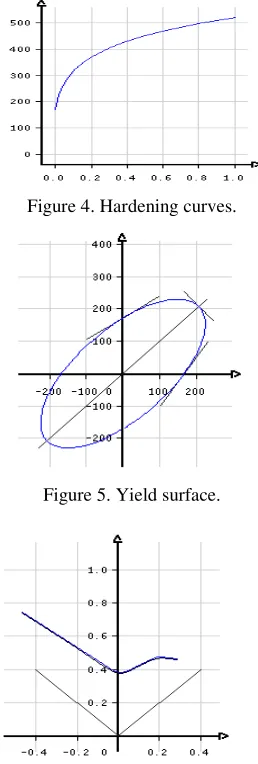
[image:2.612.369.498.284.666.2]significant impact, in order to ensure the accuracy of the simulation results and robustness of the application AutoForm material generator, and implement a custom management material. Through the material name and other information, material elasticity and gravity parameters hardening curve, yield criterion, forming defined limit curve like complete custom car oil pan material, forming a corresponding hardening curve, the yield surface diagrams and forming limit curve, as shown in Figures 4 to 6.
Figure 4. Hardening curves.
Figure 5. Yield surface.
Figure 6. Forming limit curve.
3 ESTABLISH STAMPING MODEL
process", including its work on the finite element mesh generation tools and repair; in the sense of the grid tools isometric copy; to isometric replication tool for implementing the split, separating the punch and blank holder; the establishment of a cover blank grid data; assembly location; drawbead model; setting material parameters; the displacement boundary constraints; set control parameters; generating The output data.
Car oil pan "before the simulation process." Figure 2 analysis, finite element model is mainly drawing, shaping, trimming and flanging four key steps.
3.1 Finite element modeling and drawing process
Drawing can be divided into single-action drawing, double-action drawing and the secondary drawing, the general shape of complex deep-drawing pieces of dual-acting press forming, which uses double-action drawing. With the development of modern machine tool technology, single-action press has been able to overcome the above mentioned disadvantages and advantages on the press production speed, so the car oil pan Single Action drawing application.
[image:3.612.346.531.206.317.2]Single Action Drawing tool movement in three movements, as shown in FIG. The first action of gravity is an analog stamping, sheet material placed on the blank holder status, in which case none of the punch and die movement, and none of the contact sheet. Specific gravity step the mold die is not activated, punch and blank holder stationary. The second action is to simulate the closed mold clamping action, this time downward movement of the die, punch and binder ring stationary, motion duration of the action is 200, that is, the die and the blank holder between distance is 200, end closure step, complete with die clamping ring closure, the webs clamped. The third action is to simulate the drawing sheet drawing process. This process continued downward movement of the die, the punch stationary clamping ring clamping force 80KN.
Figure 7. Car oil pan Single Action Drawing tool motion map.
Parts of the single-action drawing in AutoForm simulation, the whole drawing process can be simplified, the action can be decomposed into a mold in the mold open state, the pressure from the side Quanding punch stationary die still above the slider in the machine. Then the sheet on the blank holder, by positioning device positioning, and are subject to gravity. When the die with the press slide
[image:3.612.357.494.348.469.2]downward with clamping ring closure, the sheet was clamped, and continue down along with the die and the blank holder in contact with the punch clamping force, and gradually forming. Drawing process than just setting drawing step, also you need to set up at least gravity and closing step. Its setup process is to first import the model, set the stamping direction. Then select the incremental method, single-action drawing, sheet information file after customizing generated input to the material, the last set of each tool and its working direction and position, namely drawing process finite element model shown in Figure 8, the simulation results As shown in Figure 9.
Figure 8. FEA models of drag and expand process.
Figure 9. Drag and expand simulation results.
3.2 Shaping step finite element modeling
In order to continue processing after drawing the parts into the exact shape and size, the need for plastic parts. Plastic drawing parts is due to a flanged member by drawing punch fillet radius is too small, or local hard molding material delay hindered pull broken, and therefore need to increase the drawing die radius or simplified local shape, and then reduced by shaping radius, so that local and shaped to conform to the shape of the target.
[image:3.612.58.290.552.633.2]simulation and finite element model corresponding to build in Fig. 10 and 11, respectively.
Figure 10. Drag and expand simulation results.
Figure 11. Plastic simulation results.
3.3 Shaping step finite element modeling
Mold parts trimming operation by the machine driven slider block trimming after shaping the blank to do a combination of trimming. Next step is trimming parts of plastic surgery procedures, introducing cutting edge models. Then add the trimming process, the application of 2D die cutting, working to define the direction of the wedge, add the cut edges and cut edges cut application type.
Flanging mold parts broken down into action, the machine slide drive block downstream plastic binder with a closed block, the blank is clamped, and with plastic blocks and blocks along a nip continue down movement in the clamping force and turn side block contacts, and gradually forming.
Flanging tool movement step two actions, the first action is simulated closed mold clamping operation, and at this time the pressure cuff block gob stationary shaping block downward movement, movement of the duration of action 400, the distance block and shaping nip between blocks 400, end closure step, shaping block complete closure and binder block parts will be clamped. The second action is to simulate the forming process of sheet metal flange. The process flange block stationary, plastic blocks and blocks nip continue downward movement, movement duration of the action is 30, which is the distance between the plastic blocks and flange blocks is 30, then the nip pressure side block force 40KN, finite element model with the
[image:4.612.75.260.61.184.2]corresponding material thinning rate simulation results shown in Figure 12 and 13, respectively.
Figure 12. Plastic simulation results.
Figure 13. Material thinning simulation results.
4 SIMULATION RESULTS ANALYSIS
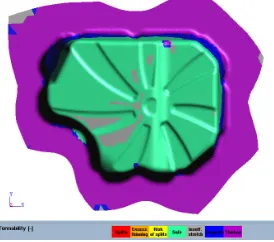
After the car oil pan forming process simulation four key step simulation by forming limit curve FLC Analyzing the simulation results of the key steps were cracking is not wrinkled, strain diagram display strain sufficient formability and uniform throughout the simulation is effective of. As it can be seen from the material thinning rate of 13, the parts thinnest 0.711mm, parts thinnest 1.22mm, further illustrate the entire design process is reasonable and can be used to guide production.
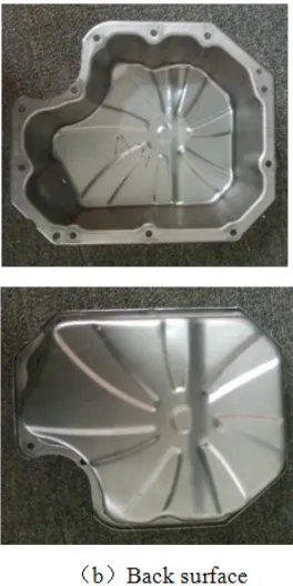
[image:4.612.338.514.65.208.2] [image:4.612.89.238.215.348.2]and position tolerances in full compliance with manufacturers provide parts diagram design requirements. After the mold only needs to put into the mold to make the necessary repairs sharpening and simple, able to adapt to punch, to meet the bulk of the parts produced.
Figure 14. Real flushing chassis castings.
5 CONCLUSION
Car oil pan deep drawing parts, the forming step is drawing, shaping, trimming and flanging, and decide the final molded article is to establish a critical mass finite element model of the drawing process.
Apply "die surface driven" finite element simulation, finite element model can be the key step of combining CATIA software AutoForm software, numerical solution after analysis of the results, and reasonably modify the process parameters, can quickly obtain high-quality analog result.
Car oil pan through the application of AutoForm software acquired drawing numerical simulations of forming the key processes that can quickly predict whether parts pulled crack, and the ability to maximize the rate of thinning parts of the data, the simulation results through evaluation, to determine whether We need to optimize the technology programs, thereby reducing the number of actual tryout late, reduce mold development cycle.
6 ACKNOWLEDGMENT
Thanks to the supports and efforts from KEY FUNDING UNIVERSITY RESEARCH FUND
PROJECT (PROJECT NUMBER: WT15004ZD) for the essay work and publishing.
Thanks to the supports of Department of Mechanical Engineering and Research institute of Mechanical engineering of Hehai University Wentian College.
Consistency of style is very important. Note the spacing, punctuation and caps in all the examples below.
REFERENCES
[1]Chen Yansi. Development and application of multi-position progressive die [[J]. Metal Processing, 2013(2):14-17. [2]Gong Zhihui, Lan Zhichun, Zhou Shunfeng. Auto cover
mold convex surface drawing method [J]. Mechanical Engineering,2014,(20):129-135.
[3]Tu Xiaowen. AutoForm Manual skills and principles wars[M]. Hubei: Hubei Science and Technology Press,2013:167-183
[4]Huang Zhaoming, Chen Zhongyou, Chen Xuejian. To a multi-level car bending sheet metal into the mold:China, 201520772012.5[P]. 2016-01-20.
[5]Huang Zhaoming, Wang Li, Liu Xiaofei, Zhang Cheng.AutoForm based on multi-station stamping forming numerical simulation[J]. JOURNAL OF HEFEI University of Technology, 2015, 38(2):157-160.
[6]Hu Ping. Automotive panel design [M]. Beijing: Mechanical and Industry Press, 2012:132-135
[7]Zheng Jie, ChengG Zezhong, Zeng Quhong. Numerical simulation and parameters within the engine cover drawing forming optimization [J]. Plastic Engineering, 2015,(1):94-98.
[8]Naranje V, Kumar S. A knowledge based system for automated design of deep drawing die for axisymmetric parts [J].Expert Systems with Applications, 2014, 41(4):1419-1431.
[9]Lin B T, Kuo C C. Application of the fuzzy-based taguchi method for the structural design of drawing dies [J].The International Journal Advanced Manufacturing Technology, 2011, 55(1/4):83-93.
[10]Huang Juan, Xiao Tiezhong, Zhao Pengzhan. Numerical simulation of car dash drawing process optimization [J].Casting technology, 2015, 40(10):138-141.