2017 2nd International Conference on Computer Science and Technology (CST 2017) ISBN: 978-1-60595-461-5
DC Motor Speed Control System in the Design and
Implementation of the Smart Car
Wei-tian KONG
a, Kai-xue YAO*, Dai-ying DONG,
Wen-qian ZHANG and Kai YAN
Institute of Computer Science and Technology, Guizhou University, Guiyang, Guizhou,China
*Corresponding author
Keyword: Governing system, Duty cycle, Register set, Control parameters.
Abstract: In the DC motor speed control system based on MK100N512ZLL10 micro controller, the duty cycle of DC motor depends on the micro controller module FTM PWM output, thereby control the car's speed indirectly. The speed is detected by the encoder and then fed back to the microcontroller, and micro controller gives the corresponding control pulse according to the corresponding situation. To make the smart car quickly and smoothly running through the entire process, we analyze the speed of encoder feedback and set appropriate PID parameters to adjust the corresponding pulse to control operation of the DC motor. Finally, the mathematical model of speed control system is constructed, and by the Matlab simulation experiment we give real-time control parameters according to actual running situation to make the whole system more reasonable and effective to control the smart car run fast and smoothly.
Introduction
In the intelligent tracking car design based on MK100N512ZLL10 micro controller, as the main module of the intelligent car, DC motor speed control system controls the car to adjust the speed smoothly in a wide range. DC motor control signal PWM is a rectangular wave signal output by the FTM counter module of microcontroller, changing the DC motor duty cycle to control the speed of the car. The micro controller needs to obtain the real-time speed to make decisions for the state of the car in next stage. The system uses two incremental encoders to obtain the speed of detection and feed it back to the microcontroller, which adjusts PID parameters according to the running condition to control the car to run with smart and steady speed changes. In the system, we use the H bridge circuit based on the MC33886 chip as a direct current to drive circuit, which can be more efficient to control the motor running [1].
System Principle and Mathematical Modeling
Speed Control System Theory
width. Pulse width adjustment means changing the duty cycle of the PWM according to requirements. The duty ratio and the instantaneous sampling value is proportional to the encoder, which can change the voltage of DC motor armature voltage value, and then the average motor hair changes so that the condition of the car and the rotation of the motor is consistent, making the motor speed, steering and stopping can be controlled in real time. The rotation process will produce deviation making the speed of the car not stable resulting in swing phenomenon, which is because that in order to get better control, the system adopts a method of closed-loop speed control, however, this kind of method is easy to produce deviations so that the car shakes. Using PID control algorithm to adjust deviation can make the car run as smoothly as possible.
Mathematical Model Building
DC motor speed control system simple circuit model is shown in Figure 1, and the voltage in circuit expressed by the formula (1).
PWM Switch
Ri
u
L n
[image:2.612.181.445.284.371.2]J
Figure 1. Fimple diagram of speed regulation system.
= + − ( )
In type:
U-power supply voltage, V; Ri-fixed resistance value,;
L-inductance coefficient, H; N-motor speed, rpm; KR-potential coefficient.
In the system, the motor torque is proportional to the armature current. When the motor loads, in order to keep the balances of torque, DC motor needs to overcome the electromagnetic torque, including load torque and damping torque, friction damping and mechanical load is generated, and the motor armature resistance friction, the hysteresis and eddy current generated by torque motor in rotating machinery. Finally, it is necessary to create an acceleration of inertia load to guarantee the torque balance, the balance formula (2).
= − (2)
In type:
J-moment of inertia, kg.m2;
Ri-fixed resistance value,;
Ki- electromagnetic torque constant;
Kn-resistance torque coefficient.
= (− + − )/ (3)
= ( − )/ (4)
By (3) (4) can get the system speed and current changes.
Hardware Design System Design
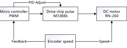
The DC motor speed control system is shown in Figure 2. The PWM and the drive circuit are the keys to the operation of the whole system, to ensure the normal and reliable operation of the color PID controller system, suitable PID control parameters of servo motor and debounce, making the car more stable, as described in the literature [3]. The drive module controls the DC motor to start stop speed according to the PWM signal, indirectly controls the car’s driving conditions. When driving, the car can adjust driving speed automatically according to different road condition, the speed cannot be obtained directly from the micro controller, so the encoder is used to detect the car speed and then feeds it back to the microcontroller, and then the microcontroller control pulse, and use the PID controller to control the car's stability, making the car drive the specified road in the shortest time.
Micro controller
PWM Drive chip pulseM33886 DC motorRN-260
Encoder speed
Feedback Speed
[image:3.612.201.414.342.423.2]PID Adjust
Figure 2. Flow chart of speed regulation system.
DC Motor Drive Circuit
Encoder Speed Principle
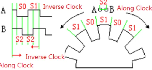
[image:4.612.161.450.256.390.2]The E6A2-CS3E encoder of system used to detect the speed of the car is an incremental encoder. The absolute encoder can also be selected, but it encodes absolute values with slow efficiency, a limitation of measuring range, and a higher price and because of high speed of DC motor in system, using absolute encoder will result in distortion. The incremental encoder is the value of the sample before and after the two values of the difference between the coding speed is fast, matching the motor speed, so in the system using incremental encoder speed detection, as described in the literature [7]. The working principle of the E6A2-CS3E is shown in Figure 3, the value of the output waveform S0:S1:S2 is not influenced by the angle encoder Duo changes, and always same as the actual ratio of waveform. During the rotation of the encoder, the steering wheel can be obtained by comparing two output values of A and B, such as [8].
Figure 3. Internal working principle of encoder.
Software Design
PWM Pulse Generation
The micro controller is a microcontroller with 32 bits, the multifunction timer module FTM of which is a 16 bits counter whose main function is to generate a PWM output, which is like a timer interrupt, the initial value and final value need to set. There are three separate FTM modules in K10, FTM0, FTM1 and FTM2. You can select the appropriate module according to the actual running condition of the car, and the DC motor can choose any of as the output of PWM, but FTM0 doesn’t has the function of orthogonal decoding and can’t count when the car runs forward and reversely, while FTM1 and FTM2 can do orthogonal decoding, but each of them has only 2 channels and FTM0 has 8. The actual selection which set the relevant registers can be as long as the module in the control program, the system chooses FTM0 as the PWM counter pulse signal source. The PWM module can adjust and change the output frequency signal in order to meet the control requirement.
PWM Pulse Wave Output Configuration
frequency depends on the first three and the frequency will be calculated automatically according to the actual need; the FTMx_CNT register is used to set the start value of the counter, generally starting with a value of 0, the same as FTMx_CNTIN register; the FTMx_MOD register is used to set the maximum value of the counter, which means setting the PWM output cycle of the PWM and it is automatically calculated in the program. If you want to configure the operating status and mode of the corresponding channel, it is necessary to set up the FTMx_CnSC register, the 2nd and 5th bits of which are used to set operation mode. The most important one is FTMx_CnV register, which is used to store the value of the channel count. The PWM output duty cycle is adjusted by setting the 0-15 bits of the register. In the system, the default clock source is the system bus clock 48mhz, and one system can only use several channels of the setting of modules in the channel, for different duty cycle settings at the same frequency.
PID Control
PID Control Principle
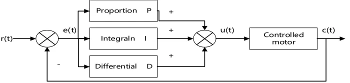
The actual speed of the car is not stable, and the car may swing left and right or speed up and slow down obtusely. We use PID algorithm to adjust the speed to make the car spend least time reaching destination. PID control algorithm is the speed deviation collected according to the proportion, integral and differential mode of regulation, its function is equivalent to a controller, such as the [9], its principle is shown in Figure 4, the r (t), c (t) and u(t) denote the set value of the system, the actual the output value and quantity control, easy to obtain the system deviation e (t) r (t) c(t) value minus. In the running process of the system if the system produces a deviation, the controller will give a appropriate ratio of P to reduce the deviation, and the system error is mainly eliminated by the integral I, so the degree of no error is improved, and the error signal transmission rate of system is adjusted by differential regulation of D. PID control improves the stability, efficiency and accuracy of the system [10]. In practice, the PID parameters need to be set according to the return value of the encoder and the driving conditions of the vehicle.
r(t)
Proportion P
Integraln I
Differential D
Controlled motor
e(t) u(t) c(t)
+
+
+
-Figure 4. PID control principle.
Debugging PID parameters
[image:5.612.140.490.489.572.2]0.6 to 0.7 times P is proportional gain P final value. Then determine the Ti, Ti will start the initial value is set to a larger constant, and decreases with the increase of Ti in the system before the shock, 1.5 to 1.8 times when the Ti value is the final value of I integral, the integral time constant Td is about 0.3 times the system shocks, but most of the time is 0. Finally, the differential terms in the system without load, with the load of debugging, after the completion of a comprehensive fine-tuning to achieve the best results can be.
System Verification
Speed Control System Simulation
[image:6.612.135.474.237.426.2]DC motor speed control system simulation is completed with Matalab, and the model constructed by its Simulink is shown in figure 5.
Figure 5. DC motor speed regulation model.
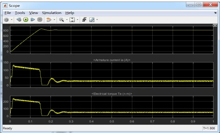
Speed control system simulation diagram is shown in figure 6. It can be seen from the diagram that with the change of PID value, the system is more stable.
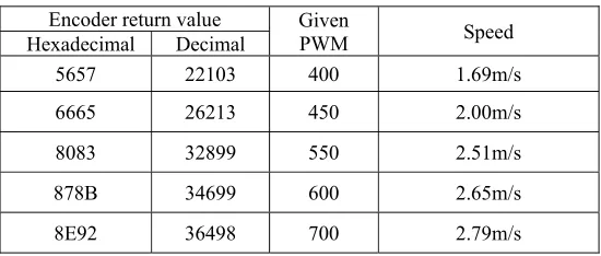
[image:6.612.131.482.480.693.2]In the case of racing wheel rotation, the encoder will be sent back to the host computer a column of sixteen hexadecimal numbers, the number of PWM can know the number of pulses. Motor idling, different PWM value encoder returns different values, and the values are generally larger. In practice, the relationship of the car speed and the PWM is shown in table 1. The encoder each turn issued 500 pulse encoder gear and axle gear ratio of the number of car 18/74, car wheel circumference 0.157m, according to table 1 the car driving formula of P/500* (18/74) *0.157, where P is the number of pulses per second encoder measured.
Table 1. Relationship between racing speed and PWM.
Encoder return value Given
PWM Speed
Hexadecimal Decimal
5657 22103 400 1.69m/s
6665 26213 450 2.00m/s
8083 32899 550 2.51m/s
878B 34699 600 2.65m/s
8E92 36498 700 2.79m/s
Conclusions
System uses ARM K10 chip as the core of DC motor control and utilizes software programming to adjust and control the car’s speed. The main way to control is to change the PWM pulse duty cycle to change DC motor steering and speed, while the PWM duty cycle needs to be adjusted according to the running state of the car detected by encoder in real time, making the drive circuit can control the DC motor in terms of different PWM signals. At the same time, the design of driving circuit system improves motor drive motor double bridge, efficiency, performance and reliability of PID control algorithm of the system has greatly improve. Finally, the speed regulation model is built and simulated by Matlab. The experimental results show that the speed of the intelligent vehicle will tend to be stable with the PID regulation.
References
[1] Er-lin Liu, Xian-gju Jang. Automation &Instrumentation. 2014, 1:37-39.
[2] Peng, J, Dubay, R. Identification and adaptive neural network control of a DC motor system with dead-zone characteristics[D]. ISA transactions. 2011,50(4):588-598.
[3] Jia-rui Cui, Qing Li, Bo-liu Zang, et al. Proceedings of the CSEE. 2013, 33:190-194.
[4] Manish, Sharma, Ajay, Verma. Wavelet reduced order observer based adaptive tracking control for a class of uncertain nonlinear systems using reinforcement learning[J]. International Journal of Control Automation and Systems. 2013,11(3):496-502.
[5] Shi-bo Li, Xu Ma, Qing Zhuo. Electronic Engineering & Product World. 2009, 16(12):41-44.
[7] Xiao-yan Wen, Qiong-lin Zheng, Ke-kang Wei, et al. Transactions of China Electrotechnical Society. 2012,27(2):185-189.
[8] Hai-tao Gu, Xiang-wu Gu, Wei Qu. Electrotechnical Journal. 2005, 24(1):113-115.
[9] Tong-jing Sun, Gui-you Chen. Freescale 9S12 sixteen-bit microcontroller principle and embedded development technology[M]. Beijing:Machinery Industry Press. 2008,5.