Hardware Installation Manual
Warranty Statement
Hewlett-Packard products are warranted against defects in materials and workmanship. For Hewlett-Packard Desktop Computer Division products sold in the U.S.A. and Canada, this warranty applies for ninety (90) days from the date of delivery.* Hewlett-Packard will, at its option, repair or replace equipment which proves to be defective during the warranty period. This warranty includes labor, parts, and surface travel costs, if any. Equipment returned to Hewlett-Packard for repair must be shipped freight prepaid. Repairs necessitated by misuse of the equipment, or by hardware, software, or interfacing not provided by Hewlett-Packard are not covered by this warranty.
HP warrants that its software and firmware designated by HP for use with a CPU will execute its programming instructions when properly installed on that CPU. HP does not warrant that the operation of the CPU, software, or firmware will be uninterrupted or error free.
NO OTHER WARRANTY IS EXPRESSED OR IMPLIED, INCLUDING, BUT NOT LIMITED TO, THE IMPLIED WARRANTIES OF MERCHANTIBILITY AND FITNESS FOR A PARTICULAR PURPOSE. HEWLETT-PACKARD SHALL NOT BE LIABLE FOR CONSEQUENTIAL DAMAGES.
for Shared Resource Management
Manual Part No. 98028-90000
© Copyright Hewlett-Packard Company, 1982
This document refers to proprietary computer software which is protected by copyright. All rights are reserved. Copying or other reproduction of this program except for archival purposes is prohibited without the prior written consent of Hewlett-Packard Company.
Printing History
New editions of this manual will incorporate all material updated since the previous edition. Update packages may be issued between editions and contain replacement and additional pages to be merged into the manual by the user. Each updated page will be indicated by a revision date at the bottom of the page. A vertical bar in the margin indicates the changes on each page. Note that pages which are rearranged due to changes on a previous page are not considered revised.
The manual printing date and part number indicate its current edition. The printing date changes when a new edition is printed. (Minor corrections and updates which are incorporated at reprint do not cause the date to change.) The manual part number changes when extensive technical changes are incorporated.
June 1982 ... First Edition
October 1982 ... Second Edition 'Changes controller operating software part number and clar-ifies maximum HP-IB cable lengths on controller)
Table of Contents
Chapter 1: IntroductionPrerequisites. . . . .. 2
Resource Management Controller. . . . .. 2
Workstations - - - 3
Unpacking the Equipment . . . .. 3
Assigning Node Addresses. . . .. 4
Chapter 2: Controller Installation Controller Installation . . . .. 5
Installing Shared Peripherals. . . .. 5
Preparing the Controller. . . . .. 5
Interfaces . . . .. 6
Installing Cards in the 110 Backplane. . . . .. 6
Handling Interface Cards. . . .. 7
Interface and Memory Configuration Switches . . . .. . . .. 7
Installation Procedure. . . .. 8
HP-IB Interface Configuration ... 8
HP 98620 DMA Card Installation. . . . .. 9
HP 98625 Disc Interface Card Installation. . . . .. 9
HP 98256 256K-byte Memory Assembly Installation. . . . .. 11
HP 98629 Resource Management Interface Installation. . . . .. 12
Select Code and Interrupt Level Switches. . . .. 12
Node Address Switches. . . .. 13
Connecting Shared Peripherals. . . .. 15
Connecting HP-IB to Shared Peripherals. . . .. 15
Limitations. . . . .. 15
Connecting the HP 98625 Interface to Disc Drives. . . . .. 15
Interface Cables . . . .. 16
Physical Arrangement of Equipment . . . .. 16
Limitations. . . . .. 1 7 Connecting the Resource Management Controller to Remote Workstations ... 17
Multiplexer Installation . . . .. 1 7 Connecting Other Computers to the Multiplexer. . . . .. 18
Cable Support. . . .. 18
Interface Cables . . . .. 19
Connecting Multiple Controllers. . . .. 19
Turning on the System. . . .. 20
In Case of Difficulty. . . . .. 20
Chapter 3: Workstation Installation Installing the HP 9845B/C Shared Resource Workstation. . . . .. 22
Resource Management ROM Installation. . . .. 22
Resource Management Interface Installation. . . . .. 22
Configuring the Interface Node Address . . . .. 22
Setting the Select Code . . . .. 23
Installing the Interface . . . .. 24
Setting the Node Address Switches . . . .. 24
Installing the HP 9826/9836 Workstation. . . . .. 26
Chapter 4: Service Information
Multiplexer Theory of Operation. . . .. 28
HP 98629 Interface Theory of Operation. . . .. 31
HP 98029 Interface Theory of Operation. . . .. 33
HP 97061 Cable. . . .. 35
Disc Interface Theory of Operation. . . .. 36
Chapter
1
Introduction
The Hewlett-Packard Shared Resource Management System is a computer networking concept that enables users of HP 9845B/C and HP 9826/9836 computers to share many system resources such as mass storage and output peripherals. Multiple-user access to data files and other system resources results in more efficient use of capital and workspace, and can signifi-cantly increase productivity by making information and computing tools more accessible.
This manual contains information for configuring and installing the hardware components that comprise the Shared Resource Management System. Limited service and device repair in-formation is also provided, including schematic diagrams.
Installation procedures and limited service information are included for the following:
• HP 98629 Resource Management Interface for HP 9826/9836.
• HP 98029 Resource Management Interface for HP 9845B/C.
• HP 98028 Resource Management Multiplexer. • HP 97061 Resource Management Interface Cable.
Brief installation and configuration instructions are also included for other assemblies which have their own installation manuals (part numbers in parentheses). The information provided in this manual should be sufficient for most installations. For additional details, schematic dia-grams, and parts lists, refer to the manual indicated which is shipped with the assembly. The assemblies are:
• HP 98256 256 K-byte Memory Assembly (98256-90000).
• HP 98625 High-speed Disc Interface (98625-90000).
Prerequisites
It is assumed that you have read and are familiar with the System Planning Guide (98028-90001), and that the necessary site preparation has been completed. Be sure that you have filled out the System Map, or have drawn an equivalent to it if your system is more complex.
This section discusses the equipment that is shipped with your system so you can identify each unit and determine where it is to be installed.
Resource Management Controller
The controller consists of an HP 9826, Option 500 with special operating software that converts it into a controller for operating the shared resources used by remote workstations. The control-ler hardware package consists of the following components:
Standard Minimum Controller Hardware
Stock Number
HP 9826A HP 98256A HP 98620A HP 98625A HP 98629A HP 98028A HP 98619A Option 655 HP 10833A
09826-87905
Description
Computer
256 K-byte Memory Assembly
DMA (Direct Memory Access) Controller High-speed HP-IB Disc Interface
Resource Management Interface Resource Management Multiplexer
SRM Operating System Software
Shielded HP-IB Chaining Cable for use with shared printers
Shared Resource Management manual set
The 09826-87905 manual set includes one each of the following items:
Stock Number
09826-90080 98028-90000 98028-90001
09826-90083
09845-93071
9282-0898
System Manual Set
Description
Shared Resource Management Manual
Shared Resource Management Installation Manual Shared Resource Management System Planning Guide
HP 9826/9836 Shared Resource Management Programming
HP 9845B/C Shared Resource Management Prog-ramming
3-ring Binder
If your system uses more than one multiplexer, additional Resource Management Interfaces and any additional memory are shipped in their own separate containers, and must be installed on site. HP 97061 interface cables are shipped with interfaces when they are ordered as an interface option.
Workstations
Workstations are HP 9826/9836 and/or HP 984SB/C computers, each of which must be equipped with a minimum of a Resource Management interface. Additional interfaces for other non-shared peripherals may also be needed, depending on the application. Each resource management interface in the system is connected to a multiplexer. The multiplexer has a short integral cable (1 metre long) that must be connected to an HP 98629 interface for power. Multiplexer installation is discussed in Chapter 2; workstation installation in Chapter 3.
Unpacking the Equipment
While unpacking equipment, inspect and verify that it matches the equipment shown on the packing lists. Unpack the equipment and place it near the final operating locations as follows:
1. Remove the controller and workstation computers from their boxes, and place them near their respective installation locations. If you desire, you can plug them in and run the System Test software to verify their operation, although this is usually done after inter-faces and additional memory are installed.
2. After the computers have been located, identify the workstation Resource Management interfaces, and place them with their respective workstation computers. Do the same for any other workstation peripherals and interfaces in the system.
3. Unpack and place the shared peripherals in their operating location. Maintain proper clearances and spacing between printers and disc drives as specified in the System Planning Guide (98028-90001).
4. Place any additional memory or interfaces for the resource management controller near the controller.
5. Identify the individual HP 97061 interface cables and determine their proper routing between interfaces and multiplexers.
WARNING
BEFORE PLUGGING IN ANY EQUIPMENT, BE SURE TO CHECK ALL POWER RECEPTACLES AND VERIFY THAT THEY ARE CORRECTLY WIRED. VERIFY THAT EQUIPMENT GROUNDS, NEUTRAL AND LINE CONDUCTORS, AND ANY OTHER CON-DUCTORS ARE CONNECTED TO THE CORRECT RECEPTACLE CONTACTS. IF ANY RECEPTACLE IN THE ENTIRE SYSTEM EN-VIRONMENT IS INCORRECTLY WIRED, SERIOUS EQUIPMENT DAMAGE AND/OR PERSONAL INJURY CAN RESULT. EQUIP-MENT WARRANTIES ARE VOID WHEN EQUIPEQUIP-MENT IS CON-NECTED TO AN INCORRECTLY WIRED POWER SOURCE.
To verify receptacle wiring, use a receptacle wiring and polarity tester manufactured for that purpose. In addition, to ensure safe operation, test each receptacle with a standard receptacle tension tester used to verify the contact-retention ability of each contact in the receptacle. Be careful to check all contacts in each receptacle, and replace any defective devices. Both types of testers are available through electrical supply houses, and should be included in any electri-cian's standard tool collection.
Assigning Node Addresses
System message packets are routed according to source and destination node addresses com-bined with interface select codes. Recommended procedure is to assign single-digit addresses (0-9) to Resource Management controllers, and two-digit (10-63) addresses to workstations. This recommendation is for convenience only and is not a system requirement.
System minimum requirements are as follows:
• Node addresses can be arbitrarily assigned to any node, whether controller or workstation.
If default remote mass storage unit specifiers are used by workstation programs and operators, all interfaces in the controller MUST be set to node address O.
• Duplicate node addresses can be assigned in the same system PROVIDED no two compu-ters having identical node addresses are connected to the same multiplexer. (It is recom-mended that each computer in the system be assigned its own UNIQUE node address.)
• If you assign duplicate node addresses in a system, you risk system malfunction whenever you move a computer or rearrange cabling because two computers with identical addres-ses may inadvertently get connected to the same multiplexer.
Recommendations
The following gUidelines are adequate for most systems, and ensure reliable operation with minimum complexity and confusion.
• Assign node addresses to each controller in the system, beginning at node address O. Address 0 is the default remote mass storage identifier. Default values can be used by any workstation connected to a controller having node address O.
• If your system has more than one controller, use incrementing values for each controller, beginning with address 1 for the second controller, and so forth until all controllers have assigned node addresses.
• Assign node addresses for each workstation, beginning at address 10 (assuming there are not more than 10 controllers in the system). The usual technique is to simply assign node addresses in sequence, 10 through 63, one address for each workstation.
If any workstation has more than one resource management interface, all interfaces can be assigned the same node address, prOVided the address does not conflict with any other computer sharing a common multiplexer.
Chapter
2
Controller Installation
This chapter explains how to install the Resource Management Controller, the interfaces that connect it to the shared peripherals, and the interconnecting network that provides com-munication with remote workstations in the Shared Resource Management System. Topics included are:
• Installing the Resource Management Controller and its shared peripherals .
• Installing the interconnection network between the Controller and remote user worksta-tions.
Controller Installation
This section explains how to install the shared peripherals and connect them to the Resource Management controller. After the system hardware is installed, refer to Shared Resource Man-agement operating manuals for information about how to operate and configure the controller and install the necessary software and firmware.
Installing Shared Peripherals
Carefully unpack the shared peripherals and place them in their proper operating positions as explained in the operating manuals that accompany each peripheral. Be sure the power switch-es are turned off, then plug each peripheral into its AC power source. Interface cablswitch-es are installed later. Refer to the System Planning Guide (98028-90001 )for information concerning cable routing, power line requirements, ventilation, and related topics.
Preparing the Controller
The HP 9826 Option 500 Resource Management Controller is shipped complete with inter-faces, memory, and all operating software. Interface configuration is set to default or recom-mended operating values at the factory, and should need no changes for most applications. However, the following pages describe in detail how to install and configure memory and interfaces for those situations where you may want to change the configuration or convert a standard HP 9826 for use as a Resource Management controller. The procedure can also be used to verify that the hardware has been correctly installed.
Interfaces
Three interfaces are commonly used in Resource Management controller computers. The internal HP-IB interface connects to line printers. The HP 98625 High-speed Disc Interface is used in conjunction with an HP 98620 DMA (Direct Memory Access) card to control up to four separate disc drives for mass storage use. Each HP 98629 Resource Management Interface is used to connect the controller to remote user workstations through one HP 98028 Resource Management Multiplexer.
The procedures which follow explain how to install and configure the controller interface cards and other boards that plug into the 110 backplane. The installation procedure for the HP 98629 Resource Management Interface applies to both controller and remote workstation installa-tions.
Installing Cards in the I/O Backplane
The HP 9826/9836 computer has eight backplane slots that can be used for interface cards, memory boards, and other devices. Four slots are available for interfacing to external peripher-als. The other four slots are reserved for the DMA controller card and memory boards when the computer is used as a Shared Resource Management (SRM) Controller. Memory/DMA and peripheral interface slots are alternated from the top to the bottom of the card cage. Interfaces fit in slots 2, 4, 6, and 8, while slots 1, 3, 5, 7, and any unused interface slots can be used for memory or a DMA controller. The following diagram shows the card arrangement that is recommended for most installations.
Slot 1: 98256 256K-byte Memory #1 Address FC (Required)
Slot 2: 98629 SRM Interface #3 (Optional) or 98256 256K-byte Memory #4 Address Fa (Optional)
Slot 3: 98256 256K-byte Memory #2 Address F8 (Optional)
,~---Slot 4: 98629 SRM Interface #2 (Optional) or 98256 256K-byte Memory Address EC (Optional) Slot 5: 98256 256K-byte Memory #3
Address F4 (Optional)
Slot 6: 98629 SRM Interface #1 (Required) Slot 7: 98620 DMA (Required)
Slot 8: 98625 Disc Interface (Required) - - - I n t e r n a l HP-IB Connector
Backplane Slot Assignments
Each of the four peripheral interface slots are located slightly below the pair of threaded fasteners that hold the interface cover thumbscrews when the card is inserted. If you insert the interface into a wrong slot, the thumbscrews in the interface cover cannot mate properly with the threaded fasteners in the computer's rear panel. If a peripheral interface slot is not used for interfacing, it can be used for memory or DMA; a blank cover is then used to conceal the boards after installation.
Handling Interface Cards
Interface cards and other boards in the 110 card cage contain components that are easily damaged by static electrical discharge caused by improper handling. To minimize the risk of component damage, the interfaces and other cards are shipped in special conductive plastic bags for protection. Do not remove the card from its bag until you are ready to install it. When installing the card, be sure there is no opportunity to create a static discharge. Hold the card by the extractors or backplane cover while removing it from the bag, and avoid touching the circuitry on the card. Touch the metal surface on the computer's rear cover panel with one hand and maintain that contact while plugging the interface into the computer with the other hand. After the card is seated into the backplane connector, the risk of damage is negligible.
Whenever you need to remove a card from the computer for service or system changes, keep the card in its protective bag to prevent component damage, or place it on a work surface designed for servicing static-sensitive electronic components and assemblies.
Be careful to avoid touching the printed circuit edge connector fingers on the interface. Finger-prints promote contamination that can lead to unreliable operation. If it becomes necessary to clean the fingers, use a cotton swab and isopropyl alcohol. Be sure to avoid the possibility of electrostatic discharges while cleaning the connector fingers; both for safety, and to prevent component damage.
Interface and Memory Configuration Switches
The interface and memory configuration switches are manufactured as clusters of two to eight individual single-pole, single-throw switches combined in a single molded plastic housing. Each switch is actuated by a slide or rocker. Switch rockers may be manufactured so that they are always flush with the housing, or they may protrude above the housing on one side or the other. The switch position is always determined by which end of the rocker is depressed. If the actuator is a slider, the switch position is determined by the position of the tab on the slider. The following illustrations show how to interpret switch settings correctly; each of the three switches have identical settings.
Installation Procedure
This section explains how to configure and install all the interface cards and other assemblies that go in the card cage, and how to configure the internal HP-IB interface for proper operation with shared printers and any other devices operating from the interface. All explanations are based on the assumption that the computer is on a table or workbench, the rear panel is facing the person installing the cards in the card cage, no cards have been installed in the cage, and the power cord is disconnected.
HP-IB Interface Configuration
Before installing any cards in the card cage, the HP-IB interface must be configured as the controller of the interface bus. This is done by programming a plug-on jumper located on the circuit board below the card cage. The HP-IB configuration jumper is located approximately in the center of the bottom of the card cage opening. It should be plugged onto the center and right-hand pins. (The center and left-hand pins select the non-controller configuration.) There are also two plug-on jumpers in the left bottom area of the card cage. Do not change their configuration.
HP-IB Configuration Jumper Setting
HP 98620A DMA Card Installation
Unpack the HP 98620A DMA Card and inspect for any damage, dirty edge connector fingers, or other problems. Plug the card into card cage slot 7 (just above the bottom slot). Handle the card as explained previously, and push the card into the cage until it is firmly seated in the backplane connector.
HP 98625A Disc Interface Card Installation
Carefully unpack and inspect the disc interface as explained earlier for the DMA card. Set the interface select code and hardware interrupt level to their proper values. The card is shipped from the factory preset to select code 14, but can be set to any non-conflicting value. The hardware interrupt level must be set to 6. For simplicity, use the factory preset values.
The following figure shows the two sets of configuration switches on the interface card: Inter-face Select Code and Hardware Interrupt Level. Note the position of the most significant (MSB) and least significant (LSB) bits on each switch. The switches are shown in their factory-set (default) positions.
-
-.
.
---
-
-LSB
INTERRUPT LEVEL
o SELECT CODE
Configuration Switch Function Default Value Allowable Range
Interface Select Code (S2) Hardware Interrupt Level (Sl)
14 6
8thru31 6 only
Binary/Decimal Table of Interface Select Codes
S2 Settings MSB 43210 LSB
01000 01001 01010 01011 01100 01101 01110 01111 10000 10001 10010 10011
Decimal Value
8
9
10 11 12 13 14 15 16 17 18 19
Binary/Decimal Table of Hardware Interrupt Levels
SI
Settings Decimal Interrupt MSB LSB Value Level
0 0 0 3
0 1 1 4
1 0 2 5
1 1 3 6
S2 Settings MSB 43210 LSB
10100 10101 10110 10111 11000 11001 11010 11011 11100 11101 11110 11111
Decimal Value
20
21 22 23
24
25 26 27 28 29 30 31
No other interface card can be set at the same hard-ware interrupt level as the HP 98625A. Otherwise, system failure results.
Default switch settings are recommended for most applications.
HP 98256A 256K-byte Memory Assembly Installation
Up to three (or five if slots are available) 256K-byte memory assemblies can be installed in the controller. It is recommended that they be installed in slots 1, 3, and 5, and that the address configuration switches be set to FC, F8, and F4, respectively. If one board is installed, set it to address FC; if two, FC and F8, respectively.
If only one or two Resource Management interfaces are installed, the unused slots can be used for additional memory. Set memory cards four and five to addresses FO and EC, respectively. If any memory is removed at any time, you must begin with the lowest-address card.
Memory address switch settings for each of the five available addresses are shown in the following figure:
Address FC Address F8 Address F4
Address Fa Address EC
Memory Address Configuration Switches
After the address has been properly configured on each card, insert the card into the proper slot in the backplane card cage as previously described, making sure the card is fully seated in the backplane connector. After the memory card(s} are installed, you are ready to install the Resource Management interface(s}.
Note
HP 98629 Resource Management Interface Installation
Unpack and inspect the Resource Management interface. As with the disc interface, there are two sets of configuration switches on the interface card. One determines the interface select code and hardware interrupt level; the other sets the interface Node Address. Note the positions of the most significant (MSB) and least significant (LSB) bits on each switch. The switches are shown in their factory-set (default) positions.
MSB LSB 10000 00001
~
Switches: 1011 0101
MSB LSB
10000Doml~
0000 0000 (Node Address)
HP 98629 Resource Management Interface Configuration Switches
Select Code and Interrupt Level Switches
The switch cluster on the left configures the interface select code and hardware interrupt level for the interface. The switch on the extreme left of the cluster is not used, but should be set in the "I" position. The next two switches control the interrupt level. The left switch is the MSB; the right switch is the LSB. To ensure reliable system operation under all operating conditions, the hardware interrupt level must be set to 4. The remaining five switches on the right set the interface select code. Here are the allowable range of settings and the factory-set default values:
Configuration Switch Function Interface Select Code
Hardware Interrupt Level
Default Value
21
4
Allowable Range 8thru31
The following table shows the switch settings for all allowable interface select code values:
Binary/Decimal Table of Interface Select Codes
MSB 43210 LSB Decimal Value MSB 43210 LSB Decimal Value 01000
01001 01010 01011 01100 01101 01110 01111 10000 10001 10010 10011
8 9
10 11 12 13 14 15 16 17 18 19
10100 10101 10110 10111 11000 11001 11010 11011 11100 11101 11110 11111
Binary/Decimal Table of Hardware Interrupt Levels
Switch Settings MSB LSB
o
0o
1 1 0 1 1Decimal Value
o
1
2 3
Interrupt Level
3 Do not use
4 Use ONLY this setting 5 Do not use
6 Do not use
20 21 22 23 24 25 26 27 28 29 30
31
The default select code is adequate for most applications unless multiple interfaces are installed in a single controller. When multiple interfaces are installed, each must have a unique select code. Hardware interrupt level MUST be set to 4 on all Resource Management interfaces.
Node Address Switches
The following table shows the switch settings for all allowable node addresses.
MSB 76543210 LSB
00000000 00000001 00000010 00000011 00000100 00000101 00000110 00000111 00001000 00001001 00001010 00001011 00001100 00001101 00001110 00001111 00010000 00010001 00010010 00010011 00010100 00010101 00010110 00010111 00011000 00011001 00011010 00011011 00011100 00011101 00011110 00011111
Node Address Switch Settings
Decimal Value
o
1 2 3 4 5 6 7 8 9 10 11 12 13 14 15 16 17 18 19 20 21 22 23 24 25 26 27 28 29 30 31MSB 76543210 LSB
00100000 00100001 00100010 00100011 00100100 00100101 00100110 00100111 00101000 00101001 00101010 00101011 00101100 00101101 00101110 00101111 00110000 00110001 00110010 00110011 00110100 00110101 00110110 00110111 00111000 00111001 00111010 00111011 00111100 00111101 00111110 00111111 Decimal Value 32 33 34 35 36 37 38 39 40 41 42 43 44 45 46 47 48 49 50 51 52 53 54 55 56 57 58 59 60 61 62 63
Attempting to use values other than those specified in the table may result in improper system operation.
The computer is now ready for connection to peripherals. Place it in its normal operating position, and install the power cord by plugging it into the rear panel and into the assigned electrical power receptacle.
Connecting Shared Peripherals
Now that the controller memory and interface cards are configured and installed, you are ready to connect the controller to its shared peripherals. If the system contains more than one controller, the procedures outlined in this section apply to each controller in the system.
Connecting HP-IB to Shared Peripherals
The HP-IB interface connector is attached to the main rear panel of the Resource Managen1ent controller, and must be connected to the shared printers that are connected to the controller. Connect one end of an HP 108331 HP-IB chaining cable to the rear panel HP-IB connector,
then attach the other end to the first shared printer. Plug the cable into the connector on the computer or printer, then tighten the two retainer screws until they are finger tight.
Limitations
HP-IB shared printers can be connected in any configuration; either in a "star" or "tree" pattern, or in a serial "daisy-chain" configuration where interface cables are connected in a series path from one printer to the next until all are connected. The total length of cable that can be used to connect peripherals to a single HP-IB interface is a maximum of 20 metres2
• A total
of 8 printers can be connected to the controller (limited both by the HP-IB drivers and the number of spoolers in the controller operating system). These guidelines apply to controllers. Similar gUidelines apply to workstations that are connected to other types of HP-IB peripherals.
Eight printer spoolers are provided in the controller operating system. Up to 8 printers can be connected to each controller, but only one can be an HP 2608A3. The others (or all eight) can be any mixture of HP 2631 B/G printers.
Connecting the HP 98625 Interface to Disc Drives
The HP 98625A Disc Interface is intended ONLY for connecting the HP 9826/9836 Computer to Hewlett-Packard disc drives equipped with CS/80 controllers. Do not attempt to use the interface with any disc or controller that is not equipped for CS/80 disc commands. If you have any questions concerning compatibility of the interface and a specific drive, consult your nearest HP Sales and Service office. This section explains which interface cables can be used, and establishes gUidelines for connecting multiple drives to a single interface.
1 HP 10833 Series chaining cables have special shielded connectors and additional cable shielding to comply with new RFI and EMC requirements. Avoid using earlier model cables. Cables can be identified by the model number printed on the cable jacket.
2 A maximum of 20 metres or 2 metres per device connected to the bus, whichever is less.
3 The HP 2608A Printer HP-IB interfaces must be configured to execute CR, LF, and FF characters. SRQ (service request) must be enabled. Command priority checking is optional, and can be enabled or disabled. Refer to the printer installation manuals for details on how to configure these options.
Interface Cables
Use only HP 10833 Series interface cables to connect the disc interface to disc drives. These cables are also used to chain multiple drives together. The HP 10833 Series cables are similar in appearance to standard HP-IB or IEEE-488 chaining cables, but they have additional shielding and other features to minimize RFI and improve noise characteristics. HP 10833 cables can be identified by the model number stamped on the cable jacket. Do not use any other model HP-IB cables to connect the interface to disc drives or controllers.
Chaining cables are usually supplied with disc drives, so none is included with the disc interface.
If you need additional cables for connecting multiple drives or for changing system configura-tion, you can order any of the following lengths:
HP-IB Cables
Model Number 10833A 10833B 10833C 108330
Cable Length
1 metre 2 metres 4 metres 0.5 metre
Note that the total cable length in any application must not exceed 10 metres.
Physical Arrangement of Equipment
The high data transfer rates supported by the disc interface require special consideration when installing interface cables. Cables behave like radio-frequency transmission lines, and can affect data settling time on the high -speed logic driver outputs. Improperly terminated or incorrectly configured cable connections can set up reflections and ringing that adversely affect signal reliability. To minimize these and related problems, configure the disc drives so that the cables are connected serially from drive to drive in a "daisy chain" pattern. For best results. avoid "star" configurations where individual cables are connected from the interface to each drive.
DISC DISC DISC DISC COMPUTER
DRIVE DRIVE DRIVE DRIVE
# 1 #2 #3 #4
-o
c::=::::J CJ c:::::::J c=::::J = = = = : : Jl
JDD
Limitations
Electrical design limits require that the combined bus connections must not exceed 11 equiva-lent loads and 10 metres total line length for each interface. In addition, line length must not exceed one metre per equivalent load. (These restrictions are due to transmission line reflection characteristics and timing constraints for high data rates.) The interface presents seven equiva-lent loads. Most disc drive controllers in the CS/80 series present one equivaequiva-lent load. There-fore, up to four discs can be connected to a single interface. The maximum length of cable that can be connected to a single interface and up to four discs or equivalent loads is as follows:
Disc Interface Cable Length Limits
Equivalent Loads Maximum Total Cable Length
1 8 metres
2 9 metres
3 10 metres
4 10 metres
Consult disc operating manuals to verify the number of equivalent loads presented by each controller.
Connecting the Resource Management Controller
to Remote Workstations
Before you install the interconnecting network between computers, install the System Worksta-tions and their respective peripherals as explained in Chapter 3. After the workstaWorksta-tions are installed and connected to their respective peripherals, you are ready to install the multiplexers and interconnecting cables as explained in this section. Refer to the System Map that was filled out during site planning and preparation to determine which computers are interconnected in the System.
Multiplexer Installation
At the heart of each interconnecting network is an HP 98028 Shared Resource Multiplexer. The multiplexer acts as a SWitching device that controls message flow among the computers that are connected to it. All network communications between computers must pass through a multi-plexer. The system has no provision for passing information from one computer directly through a second computer and on to a third. All information transfers are between network controllers and user workstations.
To connect the multiplexer to its power source, plug the connector on the short multiplexer cable into the connector on the HP 98629 Resource Management Interface. Snap the two retainer clips into place so the plug cannot come loose.
All System computer connections are handled through multiplexers. You cannot connect two multiplexers directly to each other through a cable, and you cannot connect computers together without using a multiplexer. The next section explains how to connect remote Re-source Management interfaces to multiplexers.
Connecting Other Computers to the Multiplexer
The HP 98629A Resource Management Interface is designed to connect certain HP computers to Resource Management Systems. This section explains how to connect the interface to remote multiplexers.
At this point, it is assumed that all multiplexers in the system are connected to a host interface that supplies electrical power. Each multiplexer is a central switch for the computers that connect to it. Since more than one multiplexer can be connected to a single controller, there can be one, two, or three networks connected to a single controller, each multiplexer being the central switch for a single network of workstation computers.
All System connections are made with HP 97061 cables which come in various lengths as explained in the next section. Install each cable from the multiplexer to the appropriate compu-ter by first routing the cable through wiring ducts, conduits, etc. as appropriate. Afcompu-ter the cable is in place and protected from foot or vehicular traffic, connect the 50-pin connector on the HP 97061 cable assembly to the Resource Management interface, then snap the retainer clips into position. Plug the IS-pin connector on the opposite end of the cable into the multiplexer, then tighten the retainer screws to prevent the connector from coming loose. Do not overtighten the screws.
Cable Support
Note
Only two multiplexers can obtain power from a single System Con-troller. If three multiplexers are used, one must obtain power from another computer in the system that has an HP 98629 Resource Management Interface. Use an HP 97061 cable to complete the connection from the System Controller to the third multiplexer. Do not connect more than one multiplexer power cable to a given work-station.
Interface Cables
Use only HP 97061 interface cables to connect the Resource Management Interface to the network. Interface cables are available in the following four versions:
HP 97061A 10-metre cable with two connectors installed. The 50-pin connector on one end mates with the interface card. The IS-pin connector on the other end mates with the HP 98028 Resource Managment Multiplexer.
HP 970618 2S-metre cable with two connectors installed. Connectors are the same as those used on the 10-metre cable.
HP 97061C 60-metre cable with two connectors installed. Connectors are the same as those used on the 10-metre cable.
HP 970610 60-metre cable with ONE connector installed. Connectors are the same as those used on the 10-metre cable, except that the 50-pin connector is not attached to the cable. This cable is used where the cable must be fished through condUit, or pulled through wiring ducts. All materials needed for installing the connector (except tools and solder) are included with the cable. Connector assembly proc-edure is described in the cable installation note (97061-90000).
Connecting Multiple Controllers
Turning on
the System
After all hardware has been installed and all interconnections are complete, turn on the power to the controller and its peripherals. The POWER light on the multiplexer(s) should be illumin-ated, but the BUSY light should be dark. If the system has more than one controller, repeat for the other controllers in the system.
Turn on power to the remote workstation computers and their peripherals. If a multiplexer is connected to a workstation, it should also indicate POWER is on, and the BUSY light should be dark.
The Shared Resource Management System is now ready for initial system testing and checkout. Refer to the System Manual for procedures.
In
Case
of
Difficulty
Chapter
3
Workstation Installation
This chapter explains how to install user workstations in the Resource Management System. Two interfaces are used as follows:
• The HP 98029 Resource Management Interface connects the HP 9845B/C Computer to a multiplexer through an HP 97061 Cable Assembly that is also available as an interface option .
• The HP 98629 Resource Management Interface connects HP 9826/HP 9836 computers to multiplexers, either directly or through an HP 97061 Cable Assembly. The cable assem-bly is also available as an interface option.
Installing the HP
9845B/C
Workstation
Resource Management ROM Installation
The Resource Management ROM for the HP 9845B/C consists of two ROM assemblies; one with a green label, the other with a black label. The green label ROM plugs into the left-hand ROM drawer, and the black label ROM plugs into the right-hand ROM drawer.
To install each ROM, remove the drawer, plug in the ROM, and replace the drawer as follows:
1. Remove the ROM drawer by placing your thumb in the recess at the top of the drawer, then pressing up on the movable catch underneath the drawer face with your fingers. When the catch is pushed up, gently pull the drawer out.
2. Open the clear plastic cover plate by pressing in on the two ears on each side of the inside drawer face, then hinging the cover upward.
3. Plug the ROM pack into an available connector, being careful to maintain proper orienta-tion of the package in the drawer, and being sure the ROM cap mates properly with the small keys on each side of the ROM connector. Inspect to be sure that the ROM is fully seated in the connector before closing the cover.
4. Hinge the cover back down, and snap it into place. Slide the drawer back into the computer and push it in until it is fully seated and the retainer catch is engaged. Repeat the procedure for the other drawer.
Resource Management Interface Installation
The HP 98029 Interface is used to connect the HP 9845B/C to its multiplexer. The interface is equipped with a female 50-pin connector at the end of its pigtail cable that mates with the male 50-pin connector on the HP 97061 Cable Assembly. The interface does not provide any power to the cable, so the HP 98028 Multiplexer cannot be connected directly to the interface for a power source connection. Multiplexer power is obtainable ONLY from the HP 98629 Interface used in HP 9826/9836 Computers.
Unpack the interface, and inspect for any damage during shipment. Before the interface can be installed, the Node Address must be configured.
Configuring the Interface Node Address
~...--..--REMOVE 4 SCREWS ,...-- REMOVE 2 SCREWS
Side A Side B
Interface Access Screws
Configuration procedure:
1. Remove four screws from Side A and two screws from Side B as indicated in the photo-graphs. Use a # 1 POZIDRIV screwdriver.
2. Carefully separate the two halves of the interface housing. It should be unnecessary to use more than mild force. Be sure not to bend the connector pins that interconnect the two printed circuits. If you have difficulty separating the halves, verify that you have removed the correct screws.
3. The configuration switches are located on the printed circuit attached to housing side A next to the female connector socket that mates with the other side. Use a ball-point pen or other suitable tool to set the switch rockers or sliders as explained later in this section. Be sure all the switches are firmly seated in their correct positions. Use the figure accom-panying the Node Address Table to determine the proper switch orientation.
4. After the Node Address has been set, carefully plug the two halves together again, then replace and tighten the screws. The interface is now ready to be installed in the computer.
Setting the Select Code
The interface select code can be set at any time before or after the interface has been installed in the computer. The select code is determined by the setting of the rotary switch that is accessible through the hole in the top of the interface housing. To set or change the select code, use a small flat-blade screwdriver to turn the switch rotor until the arrow points to the correct setting. The select code can be any value from 1 through 12, but must be different from any other interface connected to the same computer. The setting used in most applications is select code
Note
Do not use node address 0 for workstations. The default remote mass storage unit specifier is assigned to Node Address 0 which must be a Resource Management controller. The Node Address must also be different from any other address connected to the same multi-plexer. To use the default remote mass storage unit specifier, the interface select code must be set to 5.
Installing the Interface
After the node address is correctly set and the housing is reassembled, install the interface as follows:
1. Be sure the power to the computer is turned OFF.
2. Insert the interface housing into any available slot in the I/O backplane. If an I/O expan-der is being used, the interface can also be plugged into it. Be sure the interface is fully seated into the backplane connector with the retainer clip engaged so that the interface cannot be removed unless the release is depressed.
3. Connect the interface to the HP 97061 cable that leads to the multiplexer. Snap the retainer clips into place so the connectors cannot accidentally separate. (See Chapter 2 for more information about cable and multiplexer installation.)
4. After the interface is installed and the Resource Management hardware is installed, turn the computer on and verify as explained at the end of Chapter 2.
Setting the Node Address Switches
The switch cluster in the center of the printed circuit card attached to housing side A configures the resource management Node Address. Any value from zero thru 63 can be selected pro-vided it is not the same as the address for any other node that is connected to the same multiplexer. To set a given switch to a ONE, depress the switch rocker on the side away from the connector socket that mates with the other card. To program a ZERO, depress the rocker on the side nearest the connector. Be sure the switch rockers are fully seated in their proper positions. If a slide switch is used instead of rockers, move the slide toward or away from the connector to program a ZERO or ONE, respectively.
o
1 0 LSS
\"a
I
MSB c=J@
The following table shows the switch settings for all allowable node addresses.
HP 98029 Node Address Switch Settings
MSB 543210 LSB Decimal Value MSB 543210 LSB Decimal Value
000000
a
100000 32000001 1 100001 33
000010 2 100010 34
000011 3 100011 35
000100 4 100100 36
000101 5 100101 37
000110 6 100110 38
000111 7 100111 39
001000 8 101000 40
001001 9 101001 41
001010 10 101010 42
001011 11 101011 43
001100 12 101100 44
001101 13 101101 45
001110 14 101110 46
001111 15 101111 47
010000 16 110000 48
010001 17 110001 49
010010 18 110010 50
010011 19 110011 51
010100 20 110100 52
010101 21 110101 53
010110 22 110110 54
010111 23 110111 55
011000 24 111000 56
011001 25 111001 57
011010 26 111010 58
011011 27 111011 59
011100 28 111100 60
011101 29 111101 61
011110 30 111110 62
011111 31 111111 63
Select the Node Address using the guidelines in Chapter 1.
Note
Installing the HP 9826/9836 Workstation
The HP 98629 Resource Management Interface is used to connect HP 9826/9836 Computers to the Shared Resource Management System through HP 98028 Resource Management Multi-plexers. This section explains how to install the computers as workstations. Chapter 2 discusses the use of the same computers as Resource Management controllers. The primary difference between controller and workstation computers lies in the peripherals connected to the compu-ter and the operating software that is installed in the compucompu-ter.
Plan the memory and interface requirements of the workstation to fit the application of that particular workstation, reserving one 110 backplane slot for the Resource Management inter-face. Which slot is used is unimportant, but it is usually more convenient to place interfaces that require heavy cables close to the bottom of the card cage.
Resource Management Interface Installation
Unpack the interface from the shipping container, and inspect it for damage. Be careful to follow the handling procedures outlined in Chapter 2.
Before you install the interface, configure the Interface Select Code, Hardware Interrupt Level, and Node Address switches. The select code is usually set to 21. The hardware interrupt level must be 4. Set the Node Address to the value indicated on the System Map that was prepared during site planning. Refer to Chapter 1 for node address selection gUidelines. Chapter 2 explains how to set the select code, interrupt level, and node address configuration switches.
Note
Do not use node address 0 for workstations. The default remote mass storage unit specifier is assigned to Node Address 0 which must be a System Controller. The Node Address must also be different from any other address connected to the same multiplexer. To use the default remote mass storage unit specifier, the interface select code must be set to 21.
After you have set up the interface configuration switches and verified that they are properly seated in position, plug the interface into the computer as explained in Chapter 2, then tighten the thumbscrews until they are finger tight. Place the computer in its normal operating position, and install the local peripheral interface cables. Attach the multiplexer or HP 97061 cable to the interface as explained in Chapter 2 to complete the connection to the Resource Management System. Be sure to snap the connector retainer clips onto the cable connector to prevent the connector from aCCidentally disconnecting.
Chapter
4
Service Information
The Resource Management System consists of one or more HP 9826 computers configured as controllers, one or more user workstations, and one or more HP 98028 Resource Management Multiplexers. Additional peripherals can be connected to individual computers in the system, and the interconnecting cables between computers and multiplexers complete the hardware network. This chapter discusses the theory of operation for individual devices in the system. It is provided to aid in troubleshooting at the device level after system diagnostics have been used to isolate the problem area. System diagnostics are discussed in the System Manual (09826-90080).
Topics discussed in this chapter include:
• HP 98028 Multiplexer theory of operation • HP 98629 SRM Interface theory of operation
• HP 98029 SRM Interface theory of operation
• HP 97061 Interface Cable Assembly
• HP 98625 Disc Interface theory of operation
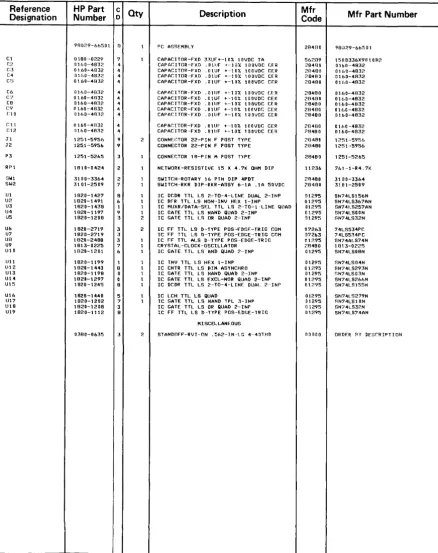
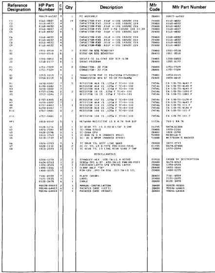
• Parts lists for multiplexer and Resource Managment interfaces
Multiplexer Theory of Operation
The HP 98028 Resource Management Multiplexer is the heart of the interconnecting network between computers in the system. It performs the switching and electrical isolation functions that enable nodes in the network to communicate safely and reliably. All multiplexer ports are electrically isolated from each other. Isolated grounds and power for each port's drivers and receivers prevent ground loops and related noise problems. The multiplexer draws electrical power from an HP 98629 Resource Management Interface through the short cable that is permanently attached to the multiplexer housing. (Power cannot be supplied from the HP
9845B/C through an HP 98029 Resource Management Interface.) Up to two multiplexers can be connected to a single Resource Management controller, but only one multiplexer can be connected to a given workstation due to power supply considerations.
Here is a multiplexer block diagram that shows the relationship between the various circuit elements:
INTEGRAL CABLE +---+-TO HP 98629
•
NON-ISOLATED PORT
DRIVERS/RECEIVERS
...
MULTIPLEXER POWER+12V ~
l
+5Vr+-+ 12V-. TIMING
AND
+5V-, CONTROL
CLOCK
+5VA ISOLATED
+5V+- POWER +5Vs
SUPPLIES
+ 12V-. +5Vc
+5Vo
Multiplexer Block Diagram
+5V+-~
.
+5V+-+5V . .
..
DRIVERS AND RECEIVERS
ISOLATED PORT #1
ISOLATED PORT #2
ISOLATED PORT #3
Power Supplies and Port Isolation
The multiplexer has a self-contained DC-to-DC converter that chops the incoming power from the HP 98629 Resource Management Interface, converts it to AC power, then uses a transfor-mer to provide four isolated power sources for the drivers and receivers that connect to remote nodes through HP 97061 cables, Opto-isolators are used to pass signals across the isolation barriers between ports.
Line Drivers and Receivers
The Line Drivers and Receivers communicate with Resource Management interfaces using balanced lines in both directions. The electrical characteristics are similar in some respects to EIA RS-422 standards, but differ in others. The four isolated ports are electrically separated from each other and the non-isolated port. There is no DC electrical continuity between any port and any other port including signal lines, power, and grounds. This isolation eliminates the potential ground-loop hazards that may arise when connecting computers together through long interconnecting cables.
Switching and Control Circuit
The switching and control circuit determines the direction of data flow through the multiplexer, and maintains proper timing between participating computers in the network. It uses the inter-nal 700 khz clock oscillator to generate the timing siginter-nals sent to participating interfaces for controlling data transmission.
The term multiplexer is somewhat inaccurate. The switching circuit more closely resembles a digital rotary switch with five ports. Data input is taken from one port at a time in a rotary sequence. As the data arrives, it is sent out on all five ports in a "broadcast" fashion. When the data transmission from the first port is finished, the second input port is selected, and so forth until all ports have been sequenced. The process is then repeated, again beginning with the first port.
To maximize multi-user access to the network, data is handled in packets using a format similar to standard SDLC (Synchronous Data Link Control) protocol. Each participating computer is allowed to transmit one packet of data after which it must wait until all other ports have been serviced before it can send the next packet. Since the data packet includes source and destina-tion informadestina-tion, it is unnecessary for the multiplexer to interpret routings. The task of identify-ing data destinations is left to the computer interfaces in the network.
As each interface receives data packets from the multiplexer, the interface decodes the packet destination node address. If the packet destination address does not match the programmed interface Node Address, the packet is ignored. If the address matches the interface node address, the interface accepts the packet and notifies the computer of its arrival.
Handshaking Between the Multiplexer and Interfaces
RT
From Multiplexer
TT Returned by
Interface
cs
J
From Multiplexer
-
...
SO
From Interface
NO PACKET TO SEND
SINGLE PACKET TRANSMISSION
Multiplexer-Interface Handshake Timing
L
...
As indicated in the timing diagram~ when the multiplexer polls an interface, it sends 16 clock cycles (approximately 23 microseconds) on the RT (Receive Timing) line, then sets CS (Clear-to-send) if the interface responds to the clock. (Note that all lines are actually differential pairs.) As soon as the interface receives the RT clock signal, it returns the clock on its TT output. If the selected interface has data to send, it immediately starts sending the SOLC flag characters on its SO output, indicating the start of a frame (packet). If there is no data to send, the SO output remains idle. When there is no SO response, the multiplexer switches to the next port at the end of the 16 clock cycles.
If the selected interface has a packet ready, it responds by sending SOLC flag characters on SO (Send Data). If the multiplexer detects activity on SO and TT, it sets CS, then maintains the open channel to the interface by holding CS and RT active until the transmission is completed. The end of a transmission is determined by the detection of eight successive bits with no zeroes. U12 and U9 are used to detect eight successive ONEs received. U12 is an 8-bit shift register that holds the most recent data. If all outputs are low (indicating eight ONEs received), CS is cleared by U9, and the controller switches to the next port.
Analog Circuits
Line impedances from the multiplexer to the interface are nominally 100 ohms. The output drivers are designed to feed a 100-ohm load. The resistor/diode and series resistor pair at each input form an approximately 100-ohm termination for the load end of the line, maintaining a balanced line with minimal reflections.
The rest of the circuitry is relatively straight-forward. The
+
12-volt supply is used to provide+
5-volt power to the isolated ports. Opto-isolators provide signal passage across isolated boundaries. U14 is a frequency divider used to generate the clock signals for timing and power-supply switching.HP 98629 Interface
Theory of Operation
The HP 98629 Resource Management Interface handles all information transfers between the computer it resides in and one or more remote computers in the system. The interface performs the following functions:
• Assemble outbound data transmissions into data packets with proper routing information included in each packet.
• Recognize timing signals from the multiplexer, and transmit message packets at the appropriate time, thus preventing data collisions.
• Recognize incoming information, and accept message packets that have the proper node address. Ignore messages containing other node addresses.
• Decode incoming message packets and transfer them to the local computer operating system or other specified destination.
• Possible electrical power to the multiplexer if the multiplexer power cable is connected to the interface.
Data Transmission
When data is being sent by the interface, the following sequence of events occurs:
• Data messages are sent to the interface by the operating system.
• The interface assembles the information into packets and adds routing information.
• The multiplexer sequentially interrogates each interface. When the appropriate timing signals are received from the multiplexer, the interface transmits a message packet.
• The multiplexer broadcasts the message packet to all of the interfaces that are connected to it.
• After the packet is transmitted, the multiplexer switches to the next interface. Timing and Clear-to-send lines to the interface are disabled. If multiple packets are being sent, the interface must wait until its next turn to send the next packet.
Data Input
Data input occurs only when an incoming packet is recognized, based on its destination node address. The following sequence of events occurs during data reception:
• The interface decodes the destination node address on all incoming data packets. If the address does not match the interface Node Address switch setting, the packet is ignored.
• If the Node Address is recognized by the interface, it accepts the packet, strips off destina-tion and control informadestina-tion, and prepares the data for transfer to the operating system or other destination level.
• The processed data is then transferred to the specified destination level for further action.
Interface Operation
When the multiplexer activates RT (Receive Timing), the interface responds ONLY if it has a packet ready to transmit. If there is at least one packet waiting for transmission, the interface synchronizes on the incoming RT signal and begins sending its timing reference clock on TT (Terminal Transmit Timing). When CS is activated by the multiplexer, it begins sending the flag characters on the SO (Send Data) line, followed by the remainder of the SDLC frame when it receives the CS signal from the multiplexer. When the frame is complete, the multiplexer disables CS and RT, causing the interface to place its outputs in an idle state.
HP 98029 Interface
Theory of Operation
The HP 98029 performs essentially the identical function on an HP 9845B/C computer as the HP 98629 performs on HP 9826/HP 9836 computers. Data transmission and reception are identical, and interaction with the multiplexer is also the same. The differences between the two interfaces lie in the interaction with the computer where they reside.
The interface consists of two printed circuit cards interconnected by two single-row connectors. The 98029-66502 board contains the 2-80 microprocessor, memory, datacomm SIO, and differential line drivers and receivers for the datacomm link to the multiplexer. The 98029-66501 contains interface circuitry between the 2-80 processor and the HP 9845 computer 110 backplane. It includes a master clock oscillator, hardware register selection circuits, and inter-rupt and handshake logic.
Data is transferred to and from the HP 9845 through the R4 registers, U6 and U7, one in each direction. Register contents are valid only if the flag is set. Register 51N provides status and interface ID information; 50UT is used to pass interface control information from the HP 9845 to the interface.
Registers 51N and 50UT are interpreted as follows:
R5IN:
15 14 13 12 11 10 9 8 7 6 5 4 3 2 o
I x I x I x I x I 1 I 0 I 0 I 1 liES I x I 0 I 0 I x lOBS I DA lOBE I
X= not used 1 = always 1 O=always 0
Bit 0 (DBE) Data Buffer Enabled: When ANDed with Bit 7, this bit indicates, when set, that the data buffer can interrupt the mainframe when the data buffer has space available for another packet.
Bit 1 (DA) Data Available: When set, the interface has a packet of information available for the mainframe.
Bit 2 (DBS) Data Buffer Status: When set, the interface has space available for another outbound data packet.
Bit 7 (IES) Interrupt Enable Status: When set, indicates that the interface can interrupt the mainframe when the prescribed conditions are met.
R50UT:
15 14 13 12 11 10 9 8 7 6 5 4 3 2 o
I x I x I x I x I x I x I x I x liEN I x I PR I x I x I x I OTE lOBE I
x = not used
Bit 0 (DBE) Data Buffer Empty: Bit set enables (clear disables) interrupt when data buffer has space available for another outbound data packet.
Bit 1 (DTE) Diagnostic Test Enable: Bit set interrupts 2-80 CPU and causes it to execute a diagnostic test. Used for factory and System Diagnostic tests.
Bit 5 (PR) Programmable Reset: Bit set causes an interface hardware reset. Automatically cleared during reset.
Bit 7 (lEN) Interrupt Enable: Enables interrupt of mainframe by interface when an incoming data packet has arrived, or when the outbound data buffer has space available for another packet (if Bit 0 is also set).
HP 97061 Cable
As mentioned earlier, the HP 97061 cable is available in 10,25, and 60 metre lengths. It is used to connect multiplexers to Resource Management interfaces, and consists of 6 twisted-pair shielded two-wire cables enclosed within an outer shield that is covered with a plastic protective jacket. Each pair has a nominal balanced transmission line impedance of approximately 100 ohms. One end has a 50-pin connector that mates with the interface. The IS-pin connector on the other end mates with anyone of the connectors on the multiplexer.
The following schematic diagram shows the pin connections and internal wiring of the cable for troubleshooting purposes. The molded connectors that are attached to the cables are not field repairable. Connector replacement requires the correct connector and the necessary tools to rewire the new connector, and is not generally recommended. Grounds must be correctly wired to ensure proper RFI performance and maintain noise immunity.
HP 98629 or HP 98029
Resource Management
Interface
43
41
18
16
17
42
44
19
48
23
2
27
33
8
24
50-Pin
ifu
I'~ - - - ? , WHT~~~--~'~~~~I--+:--~I---~:~-~\-~~~I~~~~) 2
1
II ....-RT ' 11
~~~ _ _ ~\~/~I _ _ ~_--_--_-_--_-_--_--_--_-_~-_~'-_~~~,~/~B~L~K--~)
3
tr
....-RD
- - 1- - - -, - 1 - ~ ...
1 ' 1
~~ __ ~~~-+_-~'-_-__ -_-__ -_-__ -_-__ -_-__ -~I_-~I_-~7~,~~V~IO~~4 ~CS
~----~~~-+--~---~--~~~~~~ - - 1 - - - - - - - - - - - - , - 5
1- ...
1 1 ,
~~ __ ~~~-+_-~I-__ -_-__ -_-__ -_-__ -_-__ -~-I_-~:_-~~~'~I~R~E~D--~11
1 1 1
, \ I
Ground/Common GRN
- - - I-~'"
I
~~--~~~~--~,---~'--~'--~,~,~~O~R~N~~7
1 1 , I
~~--~~~~--~: ______ S_D_~ ______ ~ __ ~:~~~:~B~R~N--~ 6
_ 1 _ 1 - _ _ _ - - - , -,-.,:,. ...
, I 1 1
~~--~~/~'71---~:---~1---~'----~~--~,T~'~\~~--~8
~ : : n-.. : ~ :
Connector Connector 15-Pin
HP 97061 Cable Schematic Diagram
HP 98028
Resource Management
Disc Interface
Theory of Operation
The HP 98625 Disc Interface is, conceptually, relatively simple. It consists of:
• a high-speed HP-IB controller contained in a single integrated circuit package,
• a DMA interface/control state machine that manages the interaction between the HP-IB controller and the DMA card, and
• interface select/control circuitry that interacts with the computer through the 110 back-plane.
The following block diagram shows the relationship of the circuit functions:
roo
-...
\
I/O BACKPLANE CONNECTOR
-
DMAINTERFACE--
..
CONTROL
HIGH-SPEED HP-IB CONTROLLER
CPU INTERFACE CONTROL
Disc Interface Block Diagram
-
---
AND CONNECTORS HP-IB CABLES TO DISC DRIVESData transfers are set up and initiated by the computer through interaction with the interface. A DMA channel is activated, and all data transmission and reception is handled through the DMA channel. Upon completion of the transfer, an interrupt to the computer is generated. The computer then suspends the DMA channel and deactivates the interfa