Systems Reference Library
File No. 1401/1460 - 28 Form C24-3334-0
Report Program Generator (on Disk) Operating Procedures
IBM 1401 and 1460
Program 1401-RG-032, Version 2
This reference publication, which contains operating procedures for IBM 1401 and 1460 Report Program Generator (on Disk), should be used in conjunction with these SRL publications:
Report Program Generator (on Disk) Specifications, IBM 1401, 1440 and 1±2.2.z Form C24-3261.
Autocoder (on Disk) Program Specifications and Operating Procedures, IBM 1401, 1440, and 1460, Form C24-3259.
Input/Output Control System (on Disk) Operating Procedures, IBM 1401 and 1460, Form C24-3298.
Input/Output Control System (on Disk) for IBM 1401 and 1460: Specifications, Form C24-1489.
This publication contains a description of the RPG program deck, system file preparation, input deck for the RPG run, Autocoder control cards, operating
instructions for generating and executing an object program, the edit listing, and halts and messages.
PREFACE
This' publication contains operating procedures for
programs written in the Report Program Generator
(on Disk) language and used on an IBM
1401-1311,IBM
1460-1301,or IBM
1460-1311Data Processing
System. This publication should be used in
conjunc-tion with the Systems Reference Library publicaconjunc-tion
Report Program Generator (on Disk) Specifications,
IBM
1401, 1440,and
1460,Form
C24-3261which
contains information concerning machine
require-ments, language specifications, output options, POR
files, and RPG control cards.
Copies of this and other IBM publications can be obtained through IBM Branch Offices.
Address comments concerning the content of this publication to IBM Product Publications, Endicott, New York 13764.
Introduction . . . .
RPG Processor Program-Deck Description System File Preparation • • • • • • • • • • •
Generating the Object Program
RPG Run • • • • • • • • • • • • • • •
Autocoder and Execution Runs·
Symbolic-Deck Option • Load-and-Go Option Object-Deck Option Edit Listing • • • • • Halts and Messages . •
Appendix . . . .
Autocoder Control Cards IBM 1401 RPG Translator • RPG Example . • • . . .
CONTENTS
5 5 5
7
7
9 9 9 10 11 17
23 23
2S
REPORT PROGHAM GENERATOR (ON DISK) OPERATING PROCEDURES IBM 1401 AND 1460
RPG PROCESSOR PROGRAM-DECK DESCRIPTION
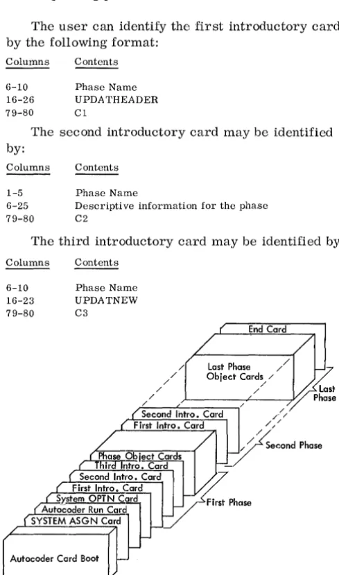
The Report Program Generator processor program is supplied in punched cards. As shown in Figure 1, the deck consists of a card boot (first 17 cards) rou-tine, SYSTEM ASGN card, AUTOCODER RUN card, SYSTEM OPTN card and the RPG phases. Each phase is preceded by three introductory phase cards.
The phases may be arranged in any order pro-vided:
1. The c:ards comprising each phase are in the correct sequence.
2. The three introductory cards preceding the cor-responding phase are in the correct order.
The user can identify the first introductory card by the following format:
Columns
6-10 16-26 79-80
Contents
Phase Name UPDATHEADER Cl
The second introductory card may be identified by:
Columns
1-5 6-25 79-80
Contents
Phase Name
Descriptive information for the phase C2
The third introductory card may be identified by:
Columns
6-10 16-23 79-80
Contents
Phase Name UPDATNEW C3
End Card
/ Last Phase / /
/ / Object
Card~
/~
/ / ~~
/ / / Phase
Second Intro. Card /// First Intro. Card
V'// /
/ / Second Phase
ir ntro. Card
-First Intro. Card Second Intro. Card ~ S)'litem OPTN Card First Phase Autoc,oder Run Card
SYSTEM ASGN Card
A"ocode,
co3
Figure 1. Processor Program Deck
Example: The first phase name will appear as RPGbb. The actual phase cards are in disk Auto-coder condensed-loader format as follows:
Columns
1-3
Contents
The 3-character machine address of the first stor-age position to be loaded.
4-5
6-72
73-75 76-80
The number of characters to be loaded from the card. Word-separator characters are not counted. The instructions and/or data to be loaded. A word-separator character (0-5-8 punch) precedes every character requiring a word mark in core storage. Sequence number of the card within the phase. RPG phase name.
The last card in the processor deck is punched END in columns 16-18.
SYSTEM FILE PRE PARA TION
The RPG (on Disk) processor program must be written on the same disk unit that contains the Auto-coder (1401-AU-008) processor program. The area of the disk unit that contains the Autocoder and RPG processor programs is called the system file.
To build a system file containing Autocoder and RPG, the user needs a program deck for both of these IBM-supplied programs. The 1401 and 1460 Disk Utility Programs (1401-UT-053) are also re-quired. To build the Autocoder system, see
a.!ll2.::..
coder (on Disk) Program Specifications and Oper-ating Procedures, IBM 1401, 1440, and 1460, Form C24-3259. An Autocoder library file, which may reside on the same disk unit as the system file, must contain the 1401 and 1460 IOCS library rou-tines (1401-10-068, Version 2). To add IOCS to the library file, see Input/Output Control System (on Disk) for IBM 1401 and 1460: Specifications, Form C24-1489 and Input/Output Control System (on Disk) Operating Procedures, IBM 1401 and 1460, Form C24-3298-0.After Autocoder has been added to the system file, and IOCS has been added to the Autocoder library file, the user may then add RPG to the sys-tem file. The RPG processor program will reside on the system file from 000900 through 002499.
To add RPG to the system when it is to reside on 1311:
1. Ready the pack on disk drive O. 2. Set the I/O check-stop switch off.
3. Set the check-stop switch and disk-write switch on.
4. Set the mode switch to RUN.
[image:5.617.67.312.276.691.2]5. In the SYSTEM ASGN card (18th card of the proc-essor deck), punch 1311 in columns 21-24.
6. Press CHECK RESET and START RESET.
7. Place RPG processor deck in 1402 read hopper. 8. To load the program, press LOAD on the 1402. 9. When the system attempts to read the last card,
press START.
To add RPG to the system when it is to reside on 1301:
1. Ready 1301 module.
2. Set the I/O check-stop switch off.
3. Set the check-stop switch and disk-write switch on.
4. Set the mode switch to RUN.
5. Press CHECK RESET and START RESET. 6. In the SYSTEM ASGN card (18th card of the
processor decks), punch 1301 in columns 21-24. 7. Place RPG processor deck in 1402 read hopper. 8. To load the program, press LOAD on the 1402. 9. When the system attempts to read the last card,
press START on the reader.
In addition to 10CS, the user must make certain that his library file includes these IBM -supplied macro instructions for use with the object program:
Multiply Divide
Two runs are required to generate an object pro-gram for a report propro-gram:
1. An RPG run. 2. An Autocoder run.
If an object deck is punched, the user will need an additional run to execute his program.
If the load-and--go option was selected, the exe-cution run follows the Autocoder run immediately, without a halt.
If the symbolic-deck option was chosen, the user can (in the Autocoder run) obtain an object program either written on disk or punched into cards.
RPG RUN
Input Decks for RPG Run
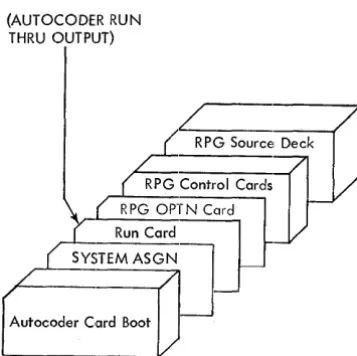
Depending on the option selected by the user, slightly di.fferent input deck configurations are necessary. The order of these decks is shown in
Figures 2 and 3.
The RPG control cards in the deck are explained in detail in Report Program Generator (on Disk) Specifications, IBM 1401, 1440, and 1460, Form C24-3261. However, information pertinent to their placement in the input deck is given in this section along with a description of the source-program deck.
(AUTOCODER RUN THRU OUTPUT)
Autocoder Card Boot
Figure 2. Input Deck for RPG Hun Using Symbolic or Object Deck Options
GENERATING THE OBJECT PROGRAM
Sequence of RPG Control Cards
Although no application of RPG can use all six con-trol cards, here is the complete list of them in the relative order in which they must appear:
1. RPG 2. TAPOUT 3. TAPIN 4. MAS 5. TRL 6. POR
Source-Program Deck
A source program deck consists of: 1. Asterisk card
2. Input specifications cards 3. Asterisk card
4. Data specifications cards 5. Asterisk card
6. Calculation specifications cards 7. Asterisk card
8. Format specifications cards 9. Asterisk card
The proper card order is ascending sequence by page and line number (columns 76-80).
The source deck can also be arranged in the Basic RPG sequence (format specifications first and input specifications last).
(AUTOCODER RUN THRU EXECUTION)
RPG Source Deck
RPG Control Cards RPG OPTN Card
Run Card
SYSTEM ASGN Card
I-+----CORELOAD ASGN Card
Autocoder Card Boot
[image:7.617.331.570.496.679.2] [image:7.617.68.247.500.678.2]ASTERISK CARDS. These cards contain only an asterisk (11-4-8 punch) in column 1. As indicated in the preceding list of cards for the input deck, one asterisk card precedes each group of specifications, and the last asterisk card follows the last specifica-tion. In the case of an application that requires no calculation specifications, two asterisk cards must follow the data specifications.
INPUT SPECIFICATIONS CARDS. These cards are punched from the Input Specifications sheet, Form X24-6590. The user prepares them by punching one card for each line he writes on the input sheet.
DATA SPECIFICATIONS CARDS. In a manner sim-ilar to that of the input cards, the user prepares the data specifications cards from the Data Specifi-cations sheet, Form X24-6591.
CALCULATION SPECIFICATIONS CARDS. These cards are punched from the Calculation Specifica-tions sheet, Form X24-6592.
FORMAT SPECIFICATIONS CARDS. These cards are punched from the Format Specifications sheet, Form X24-6593.
Sequence of RDLIN Cards
When using more than one RDLIN card, arrange them in this order:
1. Disk input-file RDLIN cards (1311 only)
(can be either of these arrangements, depending on the input file).
a. Master disk-file RDLIN, followed by the trailer disk-file RDLIN if trailers are used. b. Main disk-file RDLIN, followed by additions
disk-file RDLIN. 2. POR-file RDLIN. 3. Output-file RDLIN. 4. Tape input-file RDLIN.
System Preparation for RPG Run
1. Insert the desired forms in the printer. Install an appropriately punched carriage tape (punched in channels 1 and 12).
2. If using a 1311, mount the systems pack on disk drive O. Press the disk drive start-stop key to
turn on the drive ready light. If using a 1301, ready the module.
3. Set the disk-write switch and the check-stop switch on (to the up position). Set the 110 check stop switch off.
-4. Place the input deck for this RPG run in the 1402 read hopper. (See Input Deck for RPG Run for the contents of the input deck.)
5. If column 11 of the user's RPG control card specifies a punched symbolic program deck, place blank cards in the 1402 punch hopper.
Loading and Executing RPG
When the IBM 1401 and 1460 system preparation is completed, press the LOAD key on the 1402. In most cases the RPG run proceeds with no halts. All halts that can occur are detailed in Figure 7 in the Halts and Messages section. RPG thus performs its analysis of all of the user's control cards and report specifications. Unacceptable entries in the control cards and the specifications cards are noted on the RPG edit listing, but they do not halt the RPG program.
Output of RPG Run
1. An edit listing is printed out for all options. 2. If the user selects a symbolic deck, the
sym-bolic program is punched, the message END OF RPG is printed out, and the program halts. 3. If the user selects the object deck or the
load-and-go option, the messages END OF RPG and BEGIN AUTOCODER are printed out, and the program halts. The RPG processor has com-pleted generating the report program in symbolic (Autocoder) language and has written it in an Autocoder area of the systems pack.
The user should check the edit listing for diag-nostic messages and undefined labels and conditions.
SYMBOLIC-DECK OPTION
Input Deck for Autocoder Run
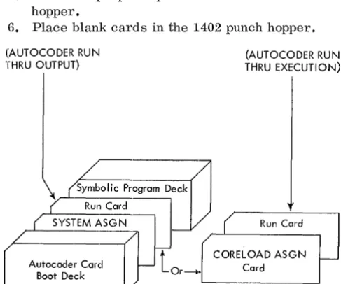
The symbolic-program deck option is completed at the end of the RPG run. The user can continue his program in two ways. Use of the Run card (AUTO-CODER RUN THRU OUTPUT) in the input deck will produce a punched deck. Use of the Run card
(AUTOCODER RUN THRU EXECUTION) will cause the object program to be written on disk, thus changing the program to a load-and-go option. A CORELOAD ASGN card must always be used with the Run card (AUTOCODER RUN THRU EXECU-TION). Fi.gure 4 depicts the input decks for either choice.
System Preparation
1. If using 1311, mount the systems pack on disk drive O. Ready the drive. If using 1301, ready the module.
2. Install forms and a 1- and 12-channel carriage tape in the printer. Ready the printer.
3. Set these switches on: DISK WRITE, CHECK STOP, and SENSE SWITCH A. Set the
I/o check
stop switch off.4. Press the check reset and the start reset keys.
If using the Run card (AUTOCODER RUN THRU OUTPUT):
5. Place the proper input deck in the 1402 read hopper.
6. Place blank cards in the 1402 punch hopper.
(AUTOCODER RUN THRU OUTPUT)
(AUTOCODER RUN THRU EXECUTION)
A
's;C:o~om
Dj)
Run Card ,
SYSTEM ASG N ( Run Card
t
CORELOAD ASGN Autocoder Card Or~~ CardI---Boot Deck
Figure 4. Input Deck for Assembly Option Using Symbolic Deck
AUTOCODER AND EXECUTION RUNS
7. Ready the 1402. 8. Press the LOAD key.
If using the Run card (AUTOCODER RUN THRU EXECUTION) :
9. Place the proper input deck in the 1402 read hopper.
10. Ready the disk unit assigned in the CORELOAD ASGN card.
11. Press the LOAD key on the 1402.
HALTS DURING AUTOCODER RUN. Sec Figure 8 in the Halts and Messages section of this manual.
Output
Using Run Card (AUTOCODER RUN THRU OUT-PUT). The output is the same as for the object-program deck option.
Using Run card (AUTOCODER RUN THRU EXECU-TION). The output is the same as for the load-and-go option.
LOAD AND GO OPTION
There is no input deck; the symbolic program is written on the systems pack.
System Preparation
1. POR-file.
a. If the POR-file is contained in disk, place the POR-FILE LIMITS card in the 1402 read hopper.
b. If a POR-file is used, supply the file and ready the unit containing it.
2. Set the CHECK STOP switch on and the 1/0
CHECK STOP switch off. If the object program is to write disk output, set the DISK WRITE switch on. Set sense switches B, C, D, as re-quired by the user I s program.
3. Make ready the proper input unit(s). If the out-put file is to be written on a pack mounted on dri ve 0, do not perform this step. See Execut-ing.
4. Make ready the necessary output unit(s). If the output file is to be written on a pack mounted on drive 0, do not perform this step. (See Exe-cuting. )
5. Press the START key.
[image:9.617.60.304.474.677.2]Output of Autocoder Run
After the assembly is completed, a program listing is printedo The object program is written in an area of the pack which the user assigned in the CORE LOAD ASGN card.
The following messages are then printed:
END OF LISTING
xxx
ERRORSCORELOAD OUTPUT COMPLETE ON 1311 UNIT X, START nnnnnn, END nnnnnn
If using 1301, the message is altered to indicate 1301 disk storage. The program docs not halt; the execution begins immediately.
Executing
The object program remains on the disk pack and is available for execution at a later time. The CORE-LOAD message gives the user the information for his INPUT ASGN card, which is necessary for later execution. See the Autocoder (on Disk) publication for details.
Autocoder loads the object program from disk storage and transfers control to the object program.
If the user specified 1311 disk input or output from his object program, the object program halts at this point. The B-address register contains 005 when this halt occurs. The purpose of this halt is to per-mit the user to remove his systems pack prior to executing his object program, and if necessary, to mount another pack on disk drive 0 for input and/or output. After he readies drive 0, the user can be-gin executing the object program by pressing the start key.
For applications in which there is no disk input or disk output, the object program does not include halt 005. In such cases, the object program begins processing the input data file upon receiving pro-gram control from Autocoder.
All other halts are detailed in Figure 9.
OBJECT-DECK OPTION
There is no input deck; the symbolic program is written on the systems pack.
System Preparation for Autocoder Run
1. Place blank cards in the 1402 punch feed. 2. Ready the punch unit.
3. Press the START key.
HALTS DURING AUTOCODER RUN. Sec Figure 8 in the Halts and Messages section of this manual.
Output of Autocoder Run
After the program listing is printed, the program prints:
END OF LISTING
xxx
ERRORSand punches an object program deck in condensed-loader format. The program then attempts to read another Autocoder control card.
Thus, for batched jobs, the user follows his source cards with the necessary Autocoder control cards for his next job. These control cards do not include the card-boot deck or the SYSTEM ASGN card.
The source cards for the last batched job can be followed by a card with HALT in columns 16-19. This same HALT card can be used if the user does not batch his jobs.
Executing the Obj ect Program
Input Deck
Under certain conditions, the object program deck must be altered. A description of the key cards for the alteration follows.
DATE CARD. Whenever the retention period of an output disk or tape file is to be checked or an output disk or tape header label is to be written by an RPG-generated program, the user must supply the current date to his object program. He does this by punching this information in the DATE card.
Columns
1-3 4-5
6
7-8 9-11
Contents
082} fixed information 05
Word-separator character (0-5-8 punch) Year (for example, 64)
Day of year (001 represents January 1, 365 repre-sents December 31).
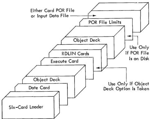
He then inserts the DATE card in the
object-program deck immediately behind the 6-card loader. Figure 5 shows the input deck for the execution run as it would be with all possible cards inserted.
RDLIN CARDS. Insert the appropriate RDLIN cards immediately behind the first EXECUTE card (identi-fied by 006 in columns 1-3) if one or more of the following conditions exist:
1. The object program will check header labels of a disk or tape input-data file.
2. The object program will check the header label of a disk or tape POR file.
Either Card POR File
or Input Data File -~~.~~ _ _ _ _ --, paR File Limits
Object Deck
r
RDLIN Cards~uteCard
!Obiect Deck
E,eea'd
( Six-Cmd Load.,
Figure 5. Input Deck for Execution Run
Use Only if Object Deck Option is Taken
When using more than one RDLIN card, arrange them in this order:
1. Disk input-file HDLIN cards (1311 only).
(Can be either of these arrangements, depending on the input file" )
a. Master disk file RDLIN followed by the trailer disk file RDLIN if trailers are used. b. Main disk file RDLIN, followed by additions
disk file RDLIN.
2. PaR-file RDLIN.
3. Output--file RDLIN. 4. Tape input-file RDLIN.
paR-FILE LIMITS CARD. Whenevertheuserelects to put his paR file on disk, he must provide the ob-ject program with the starting and ending disk sec-tor addresses in a paR FILE LIMITS card. The
paR file may be on disk only for random process-ing.
If the user chose the load-and-go option (2-punch in column 11 of the RPG control card), he places his paR FILE LIMITS card in the 1402 read hopper. It
will be the only card there.
If the user chose either of the remaining two op-tions, he places this card in the 1402 read hopper following any RDLIN cards.
This POR FILE LIMITS CARD is punched:
Columns Contcnts Explanation
1-6 xxxxxx Starting address of the POR file 7-12 xxxxxx Ending address of the POR file
[f the upper limit is unknown, the user should spec-ify the maximum expected limit. The processing will stop when lEaF, the end of file, is sensed in the paR file.
System Preparation for Object Run
1. Make ready the proper output unit(s). 2. Place the object-program deck, followed by
either the PaR-file cards (if file is in cards) or the paR-FILE LIMITS Card (if file is on disk), in the 1402 read hopper.
If PaR-file is on tape, ready the tape unit.
If the input data is in eards and hence re-quires no PaR-file, place the data file behind the obj ect deck.
3. Set sense switches B, C or D as required by the user's program.
If the card reader is being used, set sense switch A ON.
Set the CHECK STOP switch ON and the
1/0
CHECK STOP switch OFF.If the object program is to write disk output, set the DISK WRIT"E switch ON.
Press CHECK RESET and START RESET. 4. Press the 1402 LOAD key.
NOTE: All halts that can occur during this object run arc detailed in Figure 9.
EDIT LISTING
This is a listing printed on the IBM 1403 Printer.
It contains a record of the user's RPG specifications cards and his control cards, together with refer-ences to diagnostic notes when applicable. A diag-nostic note calls the user's attention to either an error in a report speCification or a control card, or an unusual calculation specification. An unusual calculation specification may not be an error. How-ever, because it is unusual it deserves attention to ensure that its use is intentional. RPG also includes in the edit listing other items of information that are valuable documentation for the source program. These items are mentioned in the following discus-sion of the contents of the edit listing.
RPG Assumptions
For certain errors that the user might make, RPG not only notes them but also makes assumptions. This permits the user to proceed if the assumed in-formation is correct for his application.
[image:11.613.60.303.66.257.2]RPG prints in numerical order all of the diagnostic notes that apply. In this group appears the message:
NOTE 88 NO CONTROL FIELD LENGTH SPECIFIED. LENGTH OF 06 IS ASSUMED.
Example 2. If the user does not specify in the RPG control card the core capacity of the 1401 or 1460 system on which he will run his object program, RPG detects this error. It prints the words, NOTE 2 on the line that lists the analysis of column 5 of the RPG control card. After it completes the control-card analysis, it prints the diagnostic notes that apply, including:
NOTE 2 NO MACHINE SIZE SPECIFIED. PROCESSING CONTINUES ASSUMING 4K.
See Figure 6 for an example of an edit listing with specification errors.
1401/60 RPG EDIT LISTING
CD PAGE
$I:::y NO LINE CAKD IMAGE
CAA
SI:::I"I 2 URECORD CAA 080
2
SI:::I"I 3 LDAAX 02
51:::1,,1 4 F KECORD210 Stlol 5 LDAA
5
5
SEI"I 6 BOXER 30
RPG CONTROL CARD COL. INFORMATION
1-3 CTL. CARD IDENT. 4 MACH. SIZE GEN. PROG. 5 MACH. SIZE OBJ. PROG. 6 SENSE SWITCHES 7 MULTIPLY-DIVIDE B ADVANCED PROGRAMMING
9 MODIFY ADD FEATURE 10 DIRECT SEEK 11 CONDENSED DECK 14-17 INPUT MEDIA 18 PRINTER OUTPUT
1~ PUNCH OUTPUT 20 DISK OUTPUT 21 DRIVE NUMBeR 22-27 LOWER LIMIT 28-33 UPPER LIMIT 34-37 BLOCK SIZE 38-40 RECORD SIZE 41-42 BLOCKING FACTOR
01
Specifications Cards
The first line of this listing contains the title, 1401/ 60 RPG EDIT LISTING. The next two lines contain headings for six columns:
CD PAGE
SEQ NO LINE CARD IMAGE DIAGNOSTIC
These six columns pertain to the ana~ysis of the speCifications cards. In the sequence column, RPG prints SEQ if a specification contains no line num-ber or if it is not in sequence by page numnum-ber and line number. The card number column identifies the specification card in the order it appears in the deck. The page and line columns print as punched in the specifications cards. The card image column contains the contents of the first 75 columns of the
PUNCHED
RPG
1 1
-NO- -YES-CARD
100
-NO-
-YES-D IAGNUS TIl;
NuTE 62
NUTE 15
NUTE 14
NOTE 6
NOTE 7
NUTE 7
NOTE 9
NoTE 8
NUTE 101
43 RESERVED BLANK
44 LABEL FOR OUTPUT FILE
-NO-- -NO-- -NO-- -NO-- -NO-- -NO-- -NO-- -NO-- -NO-- _7~0_IOENTIF~TION _ _ _ _ _ _ _ _ _ _ _ _ _ _
Figure 6. Edit Listing with Specification Errors (part 1 of 3)
MASN()20020001
LINE
DAA
DAA
NOTE 1 NOTE 6 NOTE 7
NOTE 8 NOTE 9
NOTE 14 NOTE 15 NOTE 62 NOTE 101
LABEL
RECORD
BOXER
UNIOENTIFI~D CONTROL CARD TYPE. PROCESSING CONTINUES IGNORING THIS CARD. NO DISK OUTPUT DRIVE-CONTROL NUMBER STATED. DRIVE 0 IS ASSUMED.
NO DISK OUTPUT LIMIT STATED. PROCESSING CONTINUES ASSUMING 000000 FOR LIMIT. NO DISK OUTPUT RECORD SIZE. PROCESSING CONTINUES ASSUMING 100 CHARACTERS. NO DISK OUTPUT BLUCK SIZE. PROCESSING CONTINUP ASSUMING BLOCK SIZE 100.
NOTE 1
THIS L FORMAT ENTRY HAS NU OUTPUT CONDITIONS IN COLUMNS 20-28. CONDITION 00 ASSUMED. CULUMNS 5-7 DO NOT INDICATE AN OUTPUT MEDIUM. PRINTED OUTPUT IS ASSUMED.
NO I'IELD LENGTH SPECIFIED IN COLUMNS 8-10. A LENGTH OF 006 IS ASSUMED. NO BLOCKING FACTOR. PROCESSING CONTINUES ASSUMING 1.
END POSITION ERROR POS IT ION USED
210 210 EXCEEDS UUTPUT AREA
30 030
NOTE 201 DIFFERENT OUTPUT SPECIFIED IN FORMAT SPECIFICATION~ AND CONTROL CARD.
ORDERED CALC SPECS
UNDEFINED CONDITIONS
02
RESULTING CONDI TiONS
F1 SOD F2 SOl F3 S02 F4 S03 F5 S04
F6 505 LC S06 If' S07 00 SOB OF S09
SB S10 !:iC S11 SO S12 01 S14
Figure 6. Edi.t Listing with Specification Errors (part 2 of 3)
specifications cards. The diagnostic column con-tains NOTE XXX in those cases when RPG detects
an
error. This refers to a specific diagnostic mes-sage in the list of all the errors RPG detects up un-til the time the list is printed.To illustrate, the first five lines of the control-card analysis that RPG printed are given.
Control Cards
The next portion of the edit listing is a printed anal-ysis of the user's control cards. RPG prints a heading line that identifies the control cards and the columns on the listing. It then prints the analysis of the card, one line per control-card field, giving the card columns, the meaning of the field, and either the contents of the field or a word that represents the coded contents. If the user makes an error in punching a control-card field, RPG flags the line by printing a reference to a numbered diagnostic note at the right end of the line.
RPG CONTROL CARD COL. INFORMATION PUNCHED 1-3 CTL CARD IDENT. RPG
4 MACH. SIZE GEN. PROG. NOTE 2 5 MACH. SIZE OBJ. PROG. NOTE 2 6 SENSE SWITCHES
-NO-This analysis of the RPG control card discloses two errors, flagged by the references to diagnostic note 2. (Note 2 will be printed, along with any others that apply, after RPG prints the control-card anal-ysis. )
Numbered Diagnostic Notes
[image:13.620.74.571.52.472.2], - - -
-""O~ -AOO;~:1L -:Si~rb:~N ri~~:~~:::::
-;:NOCoNSTANTS -
-
-
-
-
-
-
-
-
-
-- -
-I
UNDEFINED LABELS
BOXER F FORMAT ENTkY
END OF RPG
BEGIN AUTOCODE:R
Figure 6. Edit Listing with Specification Errors (part 3 of 3)
the errors RPG has detected up to this point, but in most cases it also indicates the action taken by the RPG processor (such as the assumptions made or that the specification is bypassed).
Field-End Error
If any format field specification card contains an in-valid entry for field end (columns 35-37), RPG prints a line that indicates the line identification, the field label, the erroneous-end position, and the position used. If columns 35-37 contain one or two blanks, RPG inserts zeros in the blank positions.
Furthermore, if the entry for the field end is greater than the size of the output area, RPG prints the diagnostic message:
EXCEEDS OUTPUT AREA
Example. If the 1403 printer has a maximum of 132 print positions, the end position should be no greater than 132.
In the edit listing shown in Figure 6, the end position is 210, a definite error. An error of this nature must be corrected before the object program is run.
Additional Program Diagnostics
Any of four program diagnostics may come at the end of the edit listing of the calculation specifica-tions. These do not indicate errors in a specific card as do the ordered calculation specifications. Instead, they refer to general conditions that are not defined on the input or format specification sheet, or to conditions on the input or format spec-ification sheets that differ from those on the control card. These errors must be corrected before pro-ceeding with the object run.
---Ordered Calculation Specifications
The next portion of the edit listing shows the cal-culation specifications, with their grouping re-arranged if necessary, so that they are in this order: all detail calculations first, in the order specified; all total calculations next, in the order specified; and all conversion calculations last, in the order specified. If RPG detected errors in its first analysis of the calculation specifications and made assumptions because of the errors, this list-ing reflects the assumptions that RPG has made.
Undefined Conditions
If the source program (the report specifications) contains any condition numbers that are not defined by either field-status entries on the data or the cal-culation specifications sheets or resulting-condition entries on the input sheet, RPG prints a list of these, under the heading UNDEFINED CONDITIONS.
Resulting Conditions
[image:14.613.48.549.57.229.2]Literals and Constants
The next portion of the edit listing is a list of all literals and constants used in the source program. The listing contains these six columns of informa-tion: the RPG-assigned label, length, decimal length, type (whether alphanumeric or numeric), the literal or the constant, and, if applicable, a diag-nostic comment indieating an error.
To illustrate, this portion of the edit listing for the sample program in the Appendix is shown.
ADDHESS LABEL
S16
S17 S18 SID
CLIENT S20
AHEA S21
DEI.. INQ. S22
DND S23
QUOT. S24
HEMAIN S25
WORDXX
DESCml'TION LEN. DEC.
23
02 04 0 05 0 10 10 00
10 0 07 0 04 0
LITEHALS AND CONSTANTS
TYPE
ALPIlANUMEHlC C:UHHENT ACCO{;!,;TS HE1'01\T ALl'IIANUMElUC OK NUMEIUC 500?
NUMElUC 2000?
ALPIIAKU~IEIUC
ALPJIANUj\IEIUC ALPIIANUJ\IEIUC NUMEI\IC NUMEHIC NUMEIUC
Next, RPG prints a list of all WORDXX constants or edit control words defined by W-entries in the for-mat specifications. This list is like the previous one, except for an additional column on the left in which WORDXX is printed.
Unreferenced Words
If the user has not used a WORDXX that he has de-fined by a W-entry, RPG lists each such word under the heading UNREFERENCED WORDS. Each line gives, in addition toWORDXX, the RPG-assigned label, the length of the word, and its decimal length.
Defined Field Names
In the next list appears every field that the user de-fined as a field name in his specifications. This list consists of these six columns: field name as defined by the user, RPG-assigned label, field length, decimal length, type (whether alphanumeric or numeric), and, if applicable, a diagnostic com-ment indicating an error.
Undefined Labels
Undefined labels (field names) are listed next. If
RPG detects a field used in a calculation or a for-mat speCification that is not defined in a specifica-tion, it prints a line that shows the name of the un-defined field and the kind of specification in which it appears under the heading Undefined Labels.
Control Fields
If the input specifications define control fields, RPG lists them, giving the length of each field. If a con-trol field were defined more than once with different lengths (an error), the line on this listing would contain the notation MULTI. DEFINED.
Additional Calculation Diagnostics
RPG performs two separate tests for calculation specifications. The results of the first test are printed in the first part of the edit listing, as de-scribed previously. The results of the second error test are printed here. This list includes only the calculation specifications that contain errors re-vealed by the second test. Each line is printed in this form:
CALC. SPEC. # xxx NOTE xxx.
The number of the specification printed here refers to the sequence number of that specification as it appears in the leftmost column of the
sorted-calculation-specification list, described previously. The reference to a numbered note indicates the specification error.
After all of these lines are listed, the numbered diagnostic notes that are applicable are printed, in sequential order.
Final Messages
For the user who chose the symbolic-program-deck output option, RPG prints the message, END OF RPG, and halts. For the other two options (that is, load-and-go and object deck in condensed-loader format) RPG prints the two messages, END OF RPG and BEGIN AUTOCODER, and halts.
Numbered Diagnostic Notes
Control Cards
NOTE 1 UNIDENTIFIED CONTROL CARD TYPE. PROCESS-ING CONTINUES IGNORPROCESS-ING THIS CARD.
NOTE 2 NO MACHINE SIZE SPECIFIED. PROCESSING CON-TINUES ASSUMING 4K.
NOTE 3 NO GENERATED OUTPUT SPECIFIED. PROCESSING CONTINUES ASSUMING MACHINE LANGUAGE DECK. NOTE 4 NO INPUT MEDIUM SPECIFIED. CARD INPUT IS
ASSUMED.
NOTE 5 NO DISK OUTPUT STATED, BUT COLUMNS 21-44 NOT BLANK. DISK OUTPUT IS ASSUMED. NOTE 6 NO DISK OUTPUT DRIVE-CONTROL NUMBER
STATED. DRIVE 0 IS ASSUMED.
NOTE 7 NO DISK OUTPUT LIMIT STATED. PROCESSING CONTINUES ASSUMING 000000 FOR LIMIT.
NOTE 8 NO DISK OUTPUT RECORD SIZE. PROCESSING CON-TINUES ASSUMING 100 CHARACTERS.
NOTE 9 NO DISK OUTPUT BLOCK SIZE. PROCESSING CON-TINUES ASSUMING BLOCK SIZE 100.
Format Specifications
NOTE 11 COLUMN 1 IS NOT L, B, F, K, OR W. TIllS CARD IS BYPASSED.
NOTE 12 COLUMN 2 IS NOT H, D, OR T. THIS L FORMAT CARD IS BYPASSED.
NOTE 13 NO FIELD END HAS BEEN SPECIFIED IN COLUMNS 35-37. POSITION 120 IS ASSUMED.
NOTE 14 THIS L FORMAT ENTRY HAS NO OUTPUT CONDI-TIONS IN COLUMNS 20-28. CONDITION 00 ASSUMED.
NOTE 15 COLUMNS 5-7 DO NOT INDICATE AN OUTPUT MEDIUM. PRINTED OUTPUT IS ASSUMED.
Data Specifications
NOTE 22 NO D IN COLUMN 1. THIS DATA CARD IS BY-PASSED.
NOTE 23 OP CODE IN COLUMNS 32, 49, OR 66 IS NOT BLANK, -, &, S, A, Y, OR D. BLANK IS ASSUMED.
Calculation Specifications
NOTE 33 NO A IN COLUMN 1. THIS CALCULATION CARD IS BYPASSED.
NOTE 34 COLUMN 46 DOES NOT CONTAIN D, 1', OR C. TIlE CALCULATION TYPE OF THE PREVIOUS CARD IS ASSUMED, UNLESS THIS IS THE FIRST CARD. IN THIS CASE, A D IS ASSUMED.
NOTE 36 OP IN COLUMN 36 IS NOT A, S, &0, -0, OR BLANK. A MOVE IS USED.
NOTE 37 STATUS IN COLUMN 14, 17, OR 20 IS NOT U, E, H, L, B, Z, N, P, OR BLANK. BLANK IS ASSUMED. NOTE 39 COLUMN 29 IS NOT C, /, x, -, &, OR BLANK.
FACTOR 1 IS IGNORED.
Input Specifications
NOTE 41 NO SCF CARD. SCF1 IS ASSUMED.
NOTE 42 NO RESULTING CONDITION IN COLUMNS 42-43. CONDITION 00 IS ASSUMED.
NOTE 44 NO C, D, T, OR S IN COLUMN 1. THIS INPUT CARD IS BYPASSED.
16
Format Specifications
NOTE 51 TIIIS F FORMAT ENTRY HAS NO FIELD NAME IN COLUMNS 29-34.
NOTE 52 NO @ AT RIGHT END OF LITERAL COLUMNS 50-75. AN @ IS ASSUMED IN COLUMN 75.
NOTE 53 THIS K FORMAT CARD HAS NO CONSTANT SPECI-FIED IN COLS. 48-75. THIS CARD IS BYPASSED. NOTE 54 COLS. 29-32 OF THIS W CARD DOES NOT DEFINE
A WORD. TIllS CARD IS BYPASSED.
NOTE 55 THIS W CARD HAS NO CONSTANT SPECIFIED IN COLS. 48-75. THIS CARD IS BYPASSED
NOTE 56 A PREVIOUS LINE OF THE SAME TYPE HAS BEEN GIVEN THE SAME DESIGNATION AS THIS LINE. NOTE 57 THIS IS NOT THE NEXT LINE AS SPECIFIED BY THE
PREVIOUS LINE.
Data Specifications
NOTE 60 INVALID STATUS IN COL. 13, 16, OR 19. NOT B, Z, N, OR P. B IS ASSUMED.
NOTE 62 NO FIELD LENGTH SPECIFIED IN COll..UMNS 8-10. A LENGTH OF 006 IS ASSUMED.
NOTE 65 NO FIELD SOURCE ENTRY. THIS CAHD IS BYPASSED.
NOTE 66 FIELD END SPECIFIED, BUT NO FIELD SOURCE. THE PREVIOUS FIELD SOURCE IS ASSUMED. NOTE 67 NO FIELD END SPECIFIED. A FIELD END OF 006
IS ASSUMED.
NOTE 68 DECIMAL LENGTH GREATER THAN FIELD LENGTH. THE LENGTHS ARE INTERCHANGED.
NOTE 69 UNDEFINED FIELD SOURCE IN COLUMNS 22-24, 39-41, 56-·58. THE PREVIOUS SOURCE IS ASSUMED.
Calculation Speci.fications
NOTE 71 NO FIELD LENGTH SPECIFIED IN COLUMNS 8-10. A LENGTH OF 006 IS ASSUMED.
NOTE 76 REMAINDER NAME SPECIFIED ON DIVIDE, NO RE-MAINDER LENGTH GIVEN. LENGTH OF 06 AS-SUMED.
Input Specifications
NOTE 85 NUMERIC SEQUENCE RECOHD HAS NO 1 OR N IN COL. 4. N IS ASSUMED.
NOTE 86 NO Z, D, OR C IN COLUMN 10, 16, 2~~, 28, 34, OR 40. C IS ASSUMED.
NOTE 87 NO RECORD CODE POSITION SPECIFIED. POSITION 006 IS ASSUMED.
NOTE 88 NO CONTROL FIELD LENGTH SPECIFIED. A LENGTH OF 06 IS ASSUMED.
NOTE 89 NO CONTROL FIELD END SPECIFIED. AN END OF 006 IS ASSUMED.
Calculation Specifications
NOTE 90 NO FACTOR 2 SPECIFIED. THIS ENTRY IS BYPASSED.
NOTE 91 OP-CODE IN COL. 29 WITH NO FACTOR 1 SPECI-FIED. THIS CARD IS BYPASSED.
NOTE 94 COMPARE OP WITH NONBLANK IN COL. 36. A BLANK IN COL. 36 IS ASSUMED.
NOTE 95 COMPARE OP WITH FIELD NAME ENTRY. FIELD NAME IS IGNORED.
NOTE 96 COMPARE OP WITH COLUMNS 14-16 BLANK. PROC-ESSING ASSUMES UOO.
NOTE 97 COMPARE-OP WITH FIELD STATUS NOT E, H, L, U" OR BLANK. U IS ASSUMED.
NOTE 98 * ALPHAMERIC COMPARE WITH DIFFERENT FIELD LENGTHS. OPERATION WILL BE PERFORMED. NOTE 99 * ARITHMETIC OPERATION WITH ALPHAMERIC
FACTOR OR FIELD NAME. OPERATION WILL BE PERFORMED.
NOTE 100 *RESULTING CONDITION WITH NO FIELD STATUS SPECIFIED. THIS STATUS MUST BE SPECIFIED.
Control Cards
NOTE 101 NO BLOCKING FACTOR. PROCESSING CONTINUES ASSUMING 1.
NOTE 102 NO TAPE UNIT SPECIFIED. PROCESSING CON-TINUES ASSUMING 1.
NOTE 103 NO RECORD LENGTH SPECIFIED. 100 CHARAC-TERS IS ASSUMED.
NOTE 104 NO BLOCK LENGTH SPECIFIED. 100 CHARACTERS IS ASSUMED.
NOTE 105 TAPE LABEL IS NOT IBM 1401 STANDARD 80, 84, OR 120 CHARACTERS. ASSUME 80.
NOTE 106 INVALID OR MISSING ENTRY IN COLUMN. COR-RECT THIS CARD WITH A VALID ENTRY. NOTE 108 TAPE LABEL OPTION NOT BLANK NOR A VALID
ENTRY. ASSUME CHECK-ALL OPTION. NOTE 109 NO CONTROL DATA FIELD COMPLETELY
DE-FINED. DIRECT ADDRESSING IS ASSUMED. NOTE 110 NO DISK DR[VE AND/OR ADDRESS SCHEME FOR
DISK FILE. ASSUME DRIVE 0, SCHEME O. NOTE 111 NO DISTANCE BETWEEN POR FIELDS STATED.
ASSUME 07.
NOTE 112 NO MAXIMUM NUMBER OF TRAILERS SPECIFIED. 1 IS ASSUMED.
NOTE 113 NO PROCESSING ORDER RECORD MEDIUM SPEC-IFIED. CARD IS ASSUMED.
NOTE 114 NO MODE OF PROCESSING STATED FOR DISK FILE. ASSUME RANDOM MODE.
NOTE 115 POR CARD COLUMN 17 CONTAINS INCORRECT ENTRY. ASSUME DISK ADDRESSES.
NOTE 116 POR CARD ENTRY FOR CONTROL-DATA LENGTH MISSING. ASSUME 07.
NOTE 117 LENGTH OF DISK ADDRESSES NOT 6, 7, OR 8. ASSUME 7.
NOTE 118 MAXIMUM NUMBER OF CONTROL-DATA OR DISK ADDRESS FIELDS PER POR MISSING. ASSUME 1. NOTE 119 NO LOCATION OF CONTROL DA T A OR DISK
ADDRESS FIELD GIVEN. ASSUME 007. NOTE 120 NO LENGTH OF NEXT RECORD FIELD GIVEN.
ASSUME LENGTH OF DISK ADDRESS.
NOTE 121 MISSING RPG CONTROL CARD. RUN SHOULD BE DISCONTINUED.
NOTE 122 TAPE INPUT MEDIUM SPECIFIED, TAPIN CARD MISSING. RUN SHOULD BE DISCONTINUED. NOTE 123 MAS AND/OR POR CARDS MISSING WITH DISK
INPUT. RUN SHOULD BE DISCONTINUED.
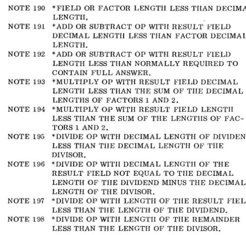
Calculation Specifications
NOTE 190 *FIELD OR FACTOR LENGTH LESS THAN DECIMAL LENGTH.
NOTE 191 *ADD OR SUBTRACT OP WITH RESULT FIELD DECIMAL LENGTH LESS THAN FACTOR DECIMAL LENGTH.
NOTE 192 *ADD OR SUBTRACT OP WITH RESULT FIELD LENGTH LESS THAN NORMALLY REQUIRED TO CONTAIN FULL ANSWER.
NOTE 193 *MULTIPLY OP WITH RESULT FIELD DECIMAL LENGTH LESS THAN THE SUM OF TIlE DECIMAL LENGTHS OF FACTORS 1 AND 2.
NOTE 194 *MULTIPLY OP WITH RESULT FIELD LENGTH LESS TIlAN THE SUM OF THE LENGTIIS OF FAC-TORS 1 AND 2.
NOTE 195 *DIVIDE OP WITH DECIMAL LENGTH OF DIVIDEND LESS THAN TIlE DECIMAL LENGTH OF TIlE DIVISOR.
NOTE 196 *DIVIDE OP WITH DECIMAL LENGTH OF THE RESULT FIELD NOT EQUAL TO TIlE DECIMAL LENGTH OF TIlE DIVIDEND MINUS THE DECIMAL LENGTH OF THE DIVISOR.
NOTE 197 *DIVIDE OP WITH LENGTH OF THE RESULT FIELD LESS THAN THE LENGTH OF THE DIVIDEND. NOTE 198 *DIVIDE OP WITH LENGTIl OF THE REMAINDER
LESS THAN THE LENGTH OF THE DIVISOR.
Additional Program Diagnostics
NOTE 200 DIFFERENT INPUT SPECIFIED IN INPUT SPECIFI-CATIONS AND CONTROL CARD.
NOTE 201 DIFFERENT OUTPUT SPECIFIED IN FORMAT SPECIFICA TIONS AND CONTROL CARD.
NOTE 202 NO INPUT SPECS IN RPG PROGRAM. PROCESSOR CANNOT CONTINUE.
NOTE 203 NO FORMAT SPECS IN RPG PROGRAM. PROC-ESSOR CANNOT CONTINUE.
NOTE * THESE MESSAGES PROBABLY DO NOT INDICATE ERRORS BUT ARE POINTS THAT REQUIRE CARE.
HALTS AND MESSAGES
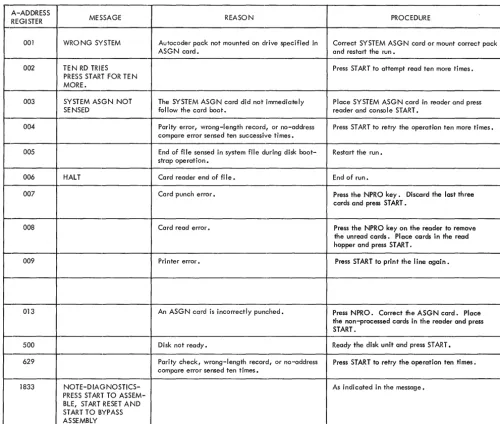
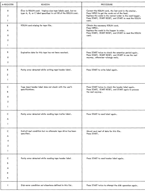
Figure 7 lists the halts that can occur while the RPG-generating run is performed. Figure 8 lists the Autocoder-run halts. Figure 9 lists the object-program-run halts. No printed messages accompany these object-time halts.
All the halts can be identified by the contents of the A-, B- or I-address register or the A-register.
[image:17.618.327.575.83.320.2]B-ADDRESS
A-REGISTER REGISTER MESSAGE REASON PROCEDURE
1 This halt indicates an error condition in read- For punch errors, the card in the stacker is the ing or punching a card. card in error. Press START to punch another
card to replace the error card. For read errors, remove the cards from the hopper and run out the cards in the feed. To restart, place the card in error (and subsequent cards) back in the hopper and press the start keys. 2 This means that either a wrong-length record Pressing the start key causes one retry.
or a no-address-compare disk error occurred during a disk-read or disk-write operation. Three additional attempts to read or write are made automatically by ,Autocoder processor before the halt occurs.
2 This means that a data check disk error Pressing the start key causes one retry. occurred on a disk-read or disk-write
opera-1 tion. The Autocoder processor tries to per-form the operation three more times before the halt occurs.
4 This means that a not-ready condition Place disk drive 0, which contains the systems occurred on a disk-read or disk-write opera- pack, ina ready status and press the start key. tion.
4 This means that the name of the run was in- Repunch the RU N card and restart the run from correctly punched into the RUN card. the beginning.
1
C NO PUNCHING This is a diagnostic halt caused by a coding ALLOWED FOR UPDATE error in the use of the update function. A LINES. PUNCHING IS
SUPRESSED. PRESS 4 ST ART TO CO NT! NUE .
B FOR BLOCKED RECORDS This halt indicates that index registers were INDEX REG. ARE not indicated in the RPG Control Card as 8 REQUIRED. PUSH START required when using the update function
IF OBJECT MACHINE with blocked records. 1 HAS INDEX REGISTERS.
B UPDATE PROGRAM NOT This halt is due to a self-checking routine Check the source coding to ensure that no CORRECTLY GENER- in the RPG processor. rules regarding the use of the update function
A ATED. have been violated.
5
222 Seven unequal-address-compare conditions Press START twice to attempt the disk operation have been detected during a disk operation. ten more times.
333 Seven parity errors have been detected during Press START twice to attempt the disk operation a disk operation. ten more times.
444 Access-inoperable error. Determine the drive number, by examining the core-storage position contained in the A-address regi ster. Alter in a different number,
if required. Press START to retry with the same or the altered drive number.
555 Seven wrong-length-record conditions have Press START'twice to attempt the disk operation been detected during a disk operation. ten more times.
31bb PROGRAM TOO LARGE This means that the amount of core storage re- Terminate the run at this point. quired to store the program being generated
exceeds the available core capacity of the generating 1401/1460 system.
32bb END OF RPG This means that the RPG processor has finished Proceed with the next step, which is the Auto-generating tha report program in symbol ic coder run. Press START to begin assembly. (Autocoder) language, and has punched the
symbolic report-program desk.
- - -
- - - ( o r ) - - f- - . -- - - -
- - - - --END OF RPG This two-line message means that the RPG pro- Proceed with the next step, which is the Auto-BEGI N AUTOCODER cessor has finished generating the report pro- coder run. Press 1447 console START to begin
gram in symbolic (Autocoder) language, and assembly. has written it in an Autocoder area of the
systems pack.
33bb NOTE 202 NO INPUT This source-program deck is incomplete. It Remove the cards from the reader-punch, make SPECS IN RPG PRO- contains no input specification cards. up a complete source-program deck, and pre-GRAM. PROCESSOR pare again for the RPG generating run. CANNOT CONTINUE.
- - -
- - - ( o r } - - -f - - - --
-- - - - -
-NOTE 203 NO FORMAT This source-program deck is incomplete. It Remove the cards from the reader-punch, make SPECS IN RPG PRO- contains no format specification cards. up a complete source-program deck, and pre-GRAM. PROCESSOR pare again for the RPG generating run. CANNOT CONTINUE.
[image:18.620.46.455.54.699.2]A-ADDRESS
MESSAGE REASON PROCEDURE
REGI STER
001 WRONG SYSTEM Autocoder pack not mounted on drive specified in Correct SYSTEM ASGN card or mount correct pack
ASGN card. and restart the run.
002 TEN RD TRIES Press START to attempt read ten more times.
PRESS START FOR TE N MORE.
003 SYSTEM ASGN NOT The SYSTEM ASGN card did not immediately Place SYSTEM ASGN card in reader and press
SENSED follow the card boot. reader and console START.
004 Parity error, wrong-length record, or no-address Press START to retry the operation ten more times. compare error sensed ten successive times.
005 End of file sensed in system file during disk boot- Restart the run. strap operation.
006 HALT Card reader end of fi Ie. End of run.
007 Card punch error. Press the NPRO key. Discard the last three
cards and press START.
008 Card read error. Press the NPRO key on the reader to remove
the unread cards. Place cards in the read hopper and press START.
009 Printer error. Press START to print the line again.
013 An ASGN card is incorrectly punched. Press NPRO. Correct the ASGN card. Place the non-processed cards in the reader and press START.
500 Disk not ready. Ready the disk unit and press START.
629 Parity check, wrong-length record, or no-address Press START to retry the operation ten times. compare error sensed ten times.
1833 NOTE-DIAGNOSTICS- As indicated in the message.
PRESS START TO ASSEM-BLE, START RESET AND START TO BYPASS ASSEMBLY
[image:19.618.54.554.66.490.2]A-REGISTER
8
2
A
8
2
B
8
2
2
C
8
2
C
A
C
A
4
2
C
B
A
8
4
REASON
Error in RDLIN card: Vaflous size tape labels used, but no type A, B, or C label specified in col 80 of the RDLIN card.
RDLIN card missing for tape .file.
Expi ration date for th is tape has not been reached.
Parity error detected wh ile writing tape header label.
T ape input header labe I does not check with the user's spec ifications.
Parity error detected while reading tape trailer label.
End-of-reel condition but no alternate tape drive has been specified.
Parity error detected while reading tape header label.
Disk-error condition not elsewhere defined in this list.
Figure 9. Object-Program Halts (part 1 of 3)
PROCEDURE
Correct the RDLI N card, the last card in the stacker. Press NPRO to get the cards out of the feed.
Replace the cards in the correct order in the read hopper. Press START, START RESET, and START to read the RDLIN card.
Obtain the necessary RDLIN card. Press NPRO.
Replace the cards in the hopper in order.
Press START, START RESET, and START to read the RDLIN card.
Press START twice to check the retention period again. Press START, START RESET, and START to use the reel anyway, otherwise--change reels.
Press START to write label again.
Press START twice to check the header label again. Press START, START RESET, and START again to process the reel anyway.
Press START to read label again.
Mount next reel of data for this file. Press START.
Press START to read header label again.
[image:20.620.50.519.65.682.2]A-REGISTER
2
C
2
4
C
4
C
4
2
4
2
8
C
A
8
2
A
8
4
C
A
8
2
REASON
Lower and upper disk-address limits of the output-file header label do not check.
Disk-header label does not contain 1 HDRb in the first five positions if disk I ight is off.
If the disk light is on, an access-inoperable condition exists on a header-Iabe I read or write operation.
Parity, wrong-length-record, or unequal-address-compare error detected while reading or writing a disk header label.
No header label found corresponding to that specified for the input file.
RDLI N information card missing for a disk file.
Card read error.
Card punch error.
Parity error detected while writing tape trailer label.
A total of thirty parity errors have been detected while attempting to write a block of data.
lao consecutive tape errors have occured on one tape read operation.
Figure 9. Object-Program Halts (part 2 of 3)
PROCEDURE
Visually check the disk pack's label information. If necessary, mount another pack, then press START twice to check the header labels.
If the new pack does not have the address range that corresponds to the address I imits given in the output-pack RDLIN card, this halt will occur again. Select the de-sired output pack, determine the range of addresses to be used, prepare a corresponding RDLI N card, and restart the job from that point.
To write on an output pack regardless of halt 2, press START, START RESET, and START; processing continues from here.
Press START, START RESET, and START to recheck, beginning with the first header label on the label track.
Press START to recheck, beginning with the first header label.
Visually check the disk pack's external label information. Correct the condition and restart the job. Proceed in the same way as for A-register halts above except press START only once (do not press START RESET) to assure that the proper pack is on-I ine before processing proceeds.
Remove cards from the feed hopper and run the remaining cards out of the feed. PlacG the proper cards, including correct RDLIN card, in the card reader. Press START, START RESET, and START.
Remove the cards from the hopper and run out the cards in the feed. To restart, place the card in error (and subsequent cards) back in the hopper cltld press the start key.
Press NPRO, remove the Iclst three cards in the stacker and discard them. Press START to repunch the error card and continue.
Press START to write label again.
Press START to attempt thirly more tries.
Turn on to diagnostic switch •. Turn off the check stop switch.
[image:21.620.103.575.62.717.2]I-ADDRESS REGISTER REASON PROCEDURE
One position after Second halt during read-correction routine Select Storage-Scan on Mode switch and scan IOCSCN card for pority-error character and correct if
pos-(lOCSCN + 1) sible.
Turn off the diagnostic switch. Turn on the check stop switch.
Press CHECK RESET, START RESET, and START to process a corrected block.
Press START to byposs an incorrect block and resume processing.
B-ADDRESS REASON PROCEDURE
REGISTER
001 When processing disk-input files, either: Press START to continue processing, ignoring the record not
I. Control-data comparison between a master record and a found. processing-order record (POR) is not equal, or
2. The search through all the records of a chain has ended, but no record was found whose control data matches that of the POR.
002 Disk-output-file upper limit has been reached. Check output file to insure that all the records have been processed. If not, the output area must be made larger to accommodate the output file.
003 Regardless of the medium of the input file, this halt means Press START to continue processing, ignoring the record that either: that caused the halt.
I. An undefined input-record type has been detected, or 2. A numeric-sequence input record is out of sequence.
004 This is the end-of-job halt for the report program.
005 This halt permits both load-and-go operation and the use of Remove the systems pack from drive O. If drive 0 is used by disk drive 0 for disk input and/or disk output. This halt the object program, mount the appropriate disk pack and ready occurs after Autocoder has loaded the object program from the the drive. Press START to begin execution of the object pro-· systems pack. This halt does not occur unless load-and-go gram.
operation and disk input and/or disk output have been specified.
222 Seven unequal-address-compare conditions have been detected Press START twice to attempt the disk operation ten more times. during a disk operation.
333 Seven pority errors have been detected during a disk operation. Press START twice to attempt the disk operation ten more times.
444 Access-inoperable error. Determine the drive number, by examing the core-storage-position contained in the A-address register. Alter in a different number, if required. Press START to retry with the same or altered drive number.
555 Seven wrong-length-record conditions have been detected Press START twice to attempt the disk operation ten more times. during a disk operation.
666 This halt occurs for labeled-output disk files only. It means If the wrong pack is mounted, mount the correct one. that the drive number specified in the object program and the If the correct one is mounted but the wrong drive number is drive number contained in the output header label do not agree. specified, alter in the correct number of the core address
contained in the A-address register. Press START to recheck all header labels.
777 This halt occurs only for labeled-output disk files and when First determine if the wrong pack is on-line, or if the wrong using a date card. It means that the area specified for disk output address limits are specified.
output contains active records. If the wrong pack is on-line, correct that condition and press START twice to check all header labels.
If the wrong output limits are specified, correct them by
altt~r-ing in the correct disk-limit addresses in the DTF area. (These are the FILESTART and FILEND DTF specifications. If the indexing and store address register special feature is specified for the object machine, the A-address register contains the high-order address of the DTF area. Otherwise, it contains the low-order address of the DTF area.) Press START twice to recheck the labels.
To use the initial output pack without altering the output-limits specifications, press START, START RESET, and START. This procedure automatically deletes the data in the file-identification field of the header label.
888 This label-check halt means that the pack serial numbers of Press START twice to check the label again.
the labeled pack and the corresponding RDLI N information Press START, START RESET, and START to proceed regardless do not agree. of the halt.
[image:22.620.49.517.64.716.2]A UTOCODER CONTROL CARDS
In addition to the HPG control cards, the user must also supply several Autocoder control cards. See Report Program Generator (on Disk) Specifications, IBM 1401, 1440, and 1460, Form C24-3261 for a discussion of the RPG control cards. The Auto-coder control cards and their contents are listed here.
SYSTEM ASGN Card
This card is always required and follows the last card of the card-boot routine. The user punches the information:
Columns
6-11 16-19
Contents
SYSTEM ASGN 21-31 1301 Unit 0
Q[
1311 Unit 0
Run Card (AUTOCODER RUN THRU OUTPUT)
If the user wants an object deck or a symbolic deck as output, he punches this card and places it in front of the RPG OPTN card. In it he punches:
Columns Contents
6-14 AUTOCODER
16-18 21-24 26-31
RUN THRU OUTPUT
CORELOAD ASGN Card
This card is used for the load-and-go option, and it precedes the Run card (AUTOCODER RUN THRU EXECUTION). If the user has only one 1311 disk drive, the START and END address shown here must be used.
Columns
6-13 16-19 .21-57
Contents
-CORE LOAD ASGN
1311 UNIT 0, START 000000, END 000200
If the user has only one module of 1301 disk storage, he must use the START and END address shown here.
APPENDIX
Columns Contents
6-13 CORELOAD
16-19 ASGN
21-57 1301 UNIT 0, START 000000, END 000200
1301 UNIT 0, START 030000, END nnnnnn (up to 199999)
If the user has more than one 1311 disk drive or 1301 module, he may enter any unit number other than
°
and any START and END address.Run Card (AUTOCODER RUN THRU EXECUTION)
If the load-and-go option was chosen, this card pre-cedes the RPG OPTN card.
Columns
6-14 16-18 21-24 26-34
Contents
AUTOCODER RUN THRU EXECUTION
RPG OPTN Card
This card must always be used and precedes the RPG control cards.
Columns
6-8 16-19
Contents
-RPG OPTN
RDLIN CARDS
RPG allows the user three label-checking options; the user can check the file-identification field, the entire label, or none of the label. Users of the load-and-go option, however, cannot check any portion of the label. Whenever an object program is to process a disk- or tape-input file or use a POR file for which label checking has been specified,
a
RDLIN card must provide label information.Disk RD LIN Card (1311 only)
Example 1. If the user chooses to check the file-identification field of a labeled disk-input file (a 2-punch in column 40 of his MAS control card), he must prepare a RDLIN card with columns 11-20 and 30-39 punched.
Example 2. If he chooses to check the entire label (a 3-punch in column 40 of MAS control card), he must punch all columns, 11-66.
Example 3. If the user does not check the labels (a 1-punch in column 40 of MAS control card), no RDLIN card is required.
The format and contents of a disk RDLIN card are: Columns 11 12 13 14 15 16-20 21-24 25-29 30-39 40-44 45-49 50 51-54 55-60 61-66 67-80 Contents
Control number of the drive with a pack containing addresses referenccd to O. See Note.
Same as column II, except referenced to 2. Same as column 11, except referenced to 4. Same as column 11, except referenced to 6. Same as column 11, except referenced to 8. RDLIN
File-retention period (days).
File creation date (of the form 62032 for Feb. I, 1962).
File identification. File serial number. Pack serial number. Blank.
File-sequence number. Lower-limit disk address Upper-limit disk address. Blank.
NOTE: The user's disk-drive assignments must always be punched in the appropriate columns. The user's application de-termines how many drive-control numbers to punch in columns 11-15.
Example. If the user's addresses are referenced to 2, 4, and 8, and if he is using drives 0, 2, and 4; he leaves columns 11 and 14 blank and punches 0 in column 12, 2 in 13 and 4 in 15.
Example. The term, addresses referenced to 0, describes sector addresses 000000-019999.
In the case of checking the label of a disk-input file that will be processed in the control-sequential mode (POR card column 16 contains a 2-punch), two input-file RDLIN cards are required: one for the main-file area and another for the additions area.
If there is not an additions area, a duplicate of the card used for the main-file area must be used.
When a disk-input file consists of both master and trailer records, two RDLIN cards are required: one for the master-record area and one for the trailer-record area.
Tape RDLIN Card
When writing the header for a tape-output file, the RDLIN cards must contain all header information
(except LABEL IDENTIFIER and TAPE SERIAL
NUMBER), not just the fields that are changed. These cards are punched in Autocoder format, with RDLIN in the operation field and the header infor-mation in the operand field in the same sequence as the header label.
The header information must correspond to the fields of the particular standard header label that is used for the file. The format of the RDL1N card associated with each of the three types of standard header labels is given in the following lists.
RDLIN card for 120-character standard header label, when fields 9-19 are not processed:
Columns
-16-20 21-24 25-29 30-39 40-44 45-48 80 Header-Label Header Information RDLIN
Retention Period Creation Date File Identification File Serial Number Reel Sequence Number
A, if all tape labels used arc not 120-character standard labels. otherwise, leave blank. Field Number 2 3 4 5 7
RDLIN card for 120-character standard header label, when fields 9-19 are processed:
Columns 16-20 21-24 25-29 30-39 40-44 45-48 49-52 53 54 55 56 57 58 59-62 63 64-68 69-73 74 75 80
Header Information
RDLIN
Retention Period Creation Date File Identification File Serial Number
Header- Label Field Number
2
3
4 5
Reel Sequence Number 7
blank 8
D~~y 9
Checksum 10
Block Sequence 11
Tape Checking/Interpreting 12 Tape Data Recording Technique 13 Tape Data Processing Technique 14
Creating System 15
Record Format 16
Rec ord Length 17
Blocking Factor/Size 18
Checkpoint 19
I, to indicate the presence of fields 9--19 A, if all tape labels used are not 120-character standard labels. otherwise, leave blank.
RDLIN card for 80-character standard header label:
Header- Label Columns Header Information Field Number
16-20 RDLIN
21-25 File Serial Number 3
26 -(minus sign) 4
27-29 Reel Sequence Number 4
30 blank 4
31-40 File Identification 5
41-45 Creation Date 6
46 - (minus sign) 7
Columns
-50 80
Header Information
Header- Label Field Number
blank
B, if all tape labels used are not 80-.character standard labels. otherwise,
leave blank.
7
RDLIN card for 84-character standard header label:
Columns Header Information
Header- Label Field Number
16-20 RDLIN 21 22-26 27 28-31 32 33-34 35 36-38 39-41 42-44 45-50 51-68 80 blank File-Serial Number blank
Reel Sequence Number blank
Creation Date: Year blank
Creation Date: Day blank
Retention Period Label Information:
blank Density Character Coding Checksum Block Sequence Checkpoint Record File Identification
C, if all tape labels do not contain 80-character standard labels. otherwise, leave blank. 3 3 4 4 4 5 5 5 6 6 7 8
Example 1. If the user desires to check just the file-identification field (a 2-punch in column 18 of TAPIN card), his RDLIN card only needs to have columns 16-20 and the file-identification field punched.
Example 2. If the entire label is to be checked (a 3-punch in column 18 of TAP.IN card), all columns need to be punched as just directed.
Example 3. If none of the label is to be checked (a I-punch in column 18 of TAPIN card), no RDLIN card is needed.
IBM 1401 HPG TRANSLA TOR
Description~
This is an IBM 1401 program that translates a re-port program that was written for the IBM 1401 Re-port Program Generator to a corresponding rep0rt program acceptable to the IBM 1401 and 1460 Re-port Program Generator (on Disk). The reRe-port
programs that can be translated are those that process card input files and fixed-length-record magnetic-tape input files. The Translator requires one control card. In it the