Simulation Study of Dynamic Fault Recovery
Performance of VSC-HVDC System
Zi-Xia Cheng, Xiao-Feng Wang*, Xi-Bo Wu, Gang Du, Fei-Yan Li
School of Electric Engineering, Zhengzhou University, Zhengzhou, China Email: *601173028@qq.com
Received 2013
ABSTRACT
The fault recovery of VSC-HVDC transmission system is often influenced by many factors, such as the reactive power compensation characteristics of the inverter and the dynamic performance of DC controllers. In this paper, the PSCAD/ EMTDC simulation tool is used to study the dynamic recovery performance of VSC-HVDC system for several different var compensating devices in VSC-HVDC inverter-Fixed capacitor (FC), Static Var compensator (SVC), and Static synchronous compensator (STATCOM) when VSC-HVDC is subject to various faults, including three phase groundings, single phase grounding and three phase breakings. The result shows that the recovery process of the whole system will be slowed down due to its negative influence on the strength of AC power system with the application of SVC, while the STATCOM can improve VSC-HVDC recovery performance greatly for its advantages over other compensating devices in areas such as voltage support ability and DC power recovery.
Keywords: VSC-HVDC; PSCAD/EMTDC; Fault Recovery; Dynamic Characteristics
1. Introduction
Because of the unique technical and economic advan- tages, the high voltage direct current (HVDC) transmis- sion technology has made a very wide range of applica- tions in the long-distance and high-capacity regional net- working transmission [1]. However, it has caused some problems in the applications [2-6]. For example, when it comes into being large disturbance, the interact- tion among ac/dc systems generally causes dynamic states mutation of the system, which causes many prob- lems, such as transient overvoltage, unstable harmonic and unstable voltage etc.
In recent years, with the development of power elec- tronics technology, especially, the study for all-control- ling power electronic devices (Gate Turn off Thyristor and Insulated Gate Bipolar Transistor) has made signifi- cant breakthrough. The new DC transmission technology (VSC-HVDC) has emerged. Compared with the tradi- tional HVDC, the current source inverter is replaced with the voltage source inverter [7,8].
At present, VSC-HVDC has been studied in mathe- matical model, control strategy and protection methods, and so on [9-13]. Zhang Gui-Bin has studied the steady state mathematical model for the VSC-HVDC system. Based on it, the control strategy for the VSC-HVDC sys- tem is proposed by using the inverse steady state model
controller to trace the operating point and using the two decoupled controlling loops to eliminate the steady state deviations [10]. Chen Qian has designed a steady-state controller based on dqo-axis. The performances of such VSC-HVDC have been analyzed, and finally the feasibil- ity and advantage have been verified by the simulation results [11]. Based on them, the research for VSC-HVDC has developed rapidly. But the operating characteristics of VSC-HVDC especially in fault cases have not drawn much attention and the kind of the situation is common in the high voltage DC system. In this paper, VSC- HVDC system model would be established with PSCAD/ EMTDC in the first place [14]. Based on this, several com- mon faults could be simulated at the AC side of VSC- HVDC system, and the dynamic recovery performance of VSC-HVDC system for several different var compen- sating devices in VSC-HVDC inverter-Fixed capacitor (FC), Static Var compensator (SVC), and Static synchronous compensator (STATCOM) would be studied. It is helpful to take appropriate measures to reduce the influence and harm caused by the fault, and provides some reference for the further study.
2. The Basic Structure and Principle of TSC
TSC is the most common compensation equipment in the reactive power compensation. It is evolved from the fixed capacitance (FC), which belongs to the parallel
*
compensation device, and it is also a branch of static var compensator (SVC) [15].
Single-phase TSC is composed of the capacitor, bidi- rectional thyristor and the current-limiting reactor with a low impedance value; it is shown in Figure 1. TSC is a kind of reactive power compensation device which made use of the thyristor as a non-contact switch, and it can fast and smoothly go into or cut off the compensation capacitors based on the accurate trigger characteristic of the thyristor. TSC can track the mutation of the impact load and give the closed-loop feedback to the best power factor quickly. It can realize the dynamic reactive power compensation and reduce the voltage fluctuation, so as to achieve the purpose of saving energy and reducing con- sumption.
[image:2.595.311.534.158.372.2]3. The Operation Principle of VSC- HVDC
Figure 2 shows the main circuit structure of the double terminal VSC-HVDC transmission system [16,17]. The main parts of the voltage source converter include: full- bridge rectifier, DC capacitor, AC converter transformer or converter reactor and ac filter. Three-phase two level topology is used for the full-bridge rectifier and each bridge arm consists of the multiple IGBTs, the DC ca- pacitor is used for providing the voltage support and buffering the impulse current when the bridge arm is turned off, at the same time, it can reduce the harmonic of DC side; The converter transformer or converter reac- tor of AC side is the link of the energy exchange between VSC and AC system, and also has the filtering effect; The AC filter is used for filtering the harmonic of DC side. The double terminal voltage source inverters are connected by the DC transmission line, and one terminal runs in the rectifier state, another end runs in the inverter state, so as to realize the active power exchange between the two ends.
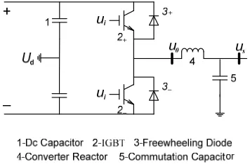
VSC-HVDC is developed from the voltage source con- verter technology and the fully controlled devices, such as IGBT. Figure 3 shows the single-phase circuit of Voltage Source Converter composed of the high fre- quency switch device IGBT. The working principle is that the trigger signal i produces from comparing the
work frequency sine signal Uc with triangular carrier
signal . It is shown in Figure 4.
U
tri
It can be seen from Figures 3 and 4, when 2
U
is
triggered, the output voltage is UoUd/ 2; when 2
is triggered, the output voltage is UoUd / 2. The 2
and are not triggered at the same time. The sine voltage
2
s u
u
in the ac bus, acquired by the converter re- actor and filter to eliminate the higher harmonic compo- nent of o, has the same waveform with c. The action
frequency of switch is detemined by tri, the phase and
amplitude of output voltage uo is detemined by c.
When the phase of is changed, it will change the
magnitude and direction of the active power; When the amplitude of c is changed, it will change magnitude
and polarity (inductive or capacitive) of the reactive power. Therefore, voltage source converter can adjust the active power and reactive power individually [18].
u u
u
c u
u
[image:2.595.332.510.389.506.2]Figure 1. Principle and structure of TSC.
[image:2.595.311.536.548.716.2]Figure 2. Double terminal VSC-HVDC transmission system.
Figure 3. Single-phase voltage source converter composed of the IGBT.
4. The Modeling and Fault Simulation of
VSC-HVDC System
4.1. The Model of Simulation System
[image:3.595.325.523.217.308.2] [image:3.595.324.522.341.510.2]At first, the mathematical model of the VSC-HVDC can be established in the PSCAD/EMTDC. It is shown in
Figure 5. The main circuit parameters are: the reference voltage of the ac system is 115 kV; the rated capacity of the transformer is S = 100 MVA and the ratio is 115 kV / 62.5 kV. The dc capacitor is 500 uF. The simulation test system uses the back-to-back operation mode. The con- troll mode of the fixed active power and constant reactive power is used by the rectifier, and the control mode of the fixed dc voltage and constant reactive power is adopted by the inverter. Based on this, the dynamic recovery characteristics of the different system faults were studied which respectively use the SVC and STATCOM instead of the FC in the ac system.
4.2. The Results and Analysis of the Simulation
4.2.1. Three Phase Grounding Fault
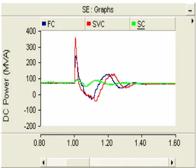
The three phase grounding belongs to a typical symmet-ric fault. The fault occurred at 1 s and disappeared at 1.05 s. The fault point was set in the ac system side of inverter. The blue represents FC; The red stands for SVC and the green represents SC (the following figures are the same to this).
Figures 6 and 7 show the dynamic recovery charac- teristics of DC power and DC voltage under the three phase grounding fault. It can be seen that the recovery of the DC power and DC voltage is the slowest when SVC is used for compensation. Because the TSC repeatedly switch during and after the fault, the system will appear the oscillation during the recovery. The recovery of the system is the fastest when SC is used. That is because SC emits and absorbs reactive power by changing the volt- age and current waveform of VSC besides it don’t need the capacitor group and shunt reactor, and there is no shortcoming of the SVC compensation runtime. The main advantage is that SC not relies on the system volt- age when it emits the capacitive reactive current, and the ability is suitable for the occasion that the system needs to support voltage during and after the fault especially [19].
4.2.2. Single Phase Grounding Fault
The single phase grounding fault is a common fault in the ac system, and also is a kind of typical asymmetric fault. The fault occurred at 1 s and disappeared at 1.05 s. The fault point was set in the ac system side of inverter.
Figures 8 and 9 show the dynamic recovery charac- teristics of DC power and DC voltage under the single phase grounding fault. They are similar with Figures 6
and 7. Among the different var compensating devices,
the recovery of the system is the fastest when SC is used, while the recovery of the dc power and dc voltage is the slowest when SVC is used for compensation, but the overall the rate of recovery increases.
4.2.3. Three Phase Breaking Fault
Three-phase breaking fault is not a common fault in practical engineering, but once it appears, it will be seri- ously harmful to the system. The fault occurred at 2 s and disappeared at 2.05 s.
[image:3.595.322.526.547.707.2]Figure 5. Model of the VSC-HVDC.
Figure 6. Dynamic recovery characteristics of DC power under the three phase grounding fault.
Figure 8. Dynamic recovery characteristics of DC power under the single phase grounding fault.
Figure 9. Dynamic recovery characteristics of DC voltage under the single phase grounding fault.
Figures 10 and 11 show the dynamic recovery character- istics of DC power and DC voltage under the three phase breaking fault. When FC is used for compensation, the recovery of the dc power and dc voltage is the slowest and when SVC is used, the system will appear a certain overvoltage, but the system recovered faster from the fault because SVC has the function of the voltage regulation; When SC is used, it only will appear a very small disturbance and the recovery of the system is the fastest.
5. Conclusions
This paper analyzed the VSC - HVDC system recovery characteristics through the power system simulation analysis software PSCAD/EMTDC. The following con- clusions can be drawn:
When SVC is used for compensation, it will lead to the ac system strength dropping further because of the structure, and make the recovery characteristics of the system worsen.
[image:4.595.69.278.284.453.2]Figure 10. Dynamic recovery characteristics of DC power under the three phase breaking fault.
Figure 11. Dynamic recovery characteristics of DC voltage under the three phase breaking fault.
When SC is used for compensation, it will increase the short-circuit capacity of ac system. It not only can provide the necessary reactive power, but also makes the system recover from the fault rapidly.
SVC and SC can rapidly and efficiently restrain the overvoltage under the three phase breaking fault, while FC has no the voltage-control function, so the capacitor and filter must be rapidly resected, in or-der to avoid ap- pearing a higher overvoltage.
Whether the suppression level of the transient overvoltage or the recovery characteristics of the dc power in the three kinds of reactive compensation modes, we can conclude that SC has more obvious advantages than other two compensations.
6. Acknowledgements
[image:4.595.317.531.294.475.2]REFERENCES
[1] W. J. Zhao, “The Engineering Technology of HVDC,” China Electric Power Press, Beijing, 2004.
[2] Y. Jing, Z. Ren, etc., “Study on Overvoltage of Tian-Guang HVDC Transmission,” High Voltage Tech-nology, Vol. 28, No. 4, 2002, pp. 1-4.
[3] A. E. Hammad, “Analysis of Second Harmonic Instability for Chateauguay HVDC/SVC Scheme,” IEEE Transac-tions on Power Delivery, Vol. 7, No. 1, 1992, pp. 410-415. doi:10.1109/61.108935
[4] P. S. Bodger, G. D. Irwin and D. A. Woodford, “Control-ling Harmonic Instability of HVDC Links Connected to Weak AC Systems,” IEEE Transaction on Power Deliv-ery, Vol. 5, No. 4, 1990, pp. 2039-2046.
doi:10.1109/61.103699
[5] X. Yang, P. Y. Lang and X. Jin, “Modeling and Analysis of Power/voltage Static Stability for HVDC Systems,” The Power of East China, Vol. 34, No. 3, 2006, pp. 16-19.
[6] B. Franken and G. Andersson, “Analysis of HVDC Con-verters Connected to Weak Ac Systems,” IEEE Transac-tion on Power System, Vol. 5, No. 1, 1990, pp. 235-242. doi:10.1109/59.49111
[7] G. F. Tang, “High Voltage DC Transmission Technology Based on VSC,” China Electric Power Press, Beijing, 2010.
[8] G. L. Zhou, X. X. Liu and X. C. Shi, “Characteristic Analysis and Parameter Design of the AC Filter of VSC-HVDC Station,” High Voltage Engineering, Vol. 36, No. 9, 2010, pp. 2329-2335,.
[9] M. Chehardeh, I. sapour, H. Lesani, etc., “An Optimal Control Strategy to Alleviate Subsynchronous Resonance in VSC-HVDC Systems,” Proceeding of 2th Power elec-tronics and Intelligent Transportation System, Shenzhen, China, 2009, pp. 250-255.
[10] G. B. Zhang, Z. Xu and G. Z. Wang, “Steady State Model and its Nonlinear Control of VSC-HVDC System,”
Zhongguo Dianji Gongcheng Xuebao, Vol. 22, No. 1, 2002, pp. 17-22. doi:10.3901/JME.2002.07.017
[11] Q. Chen, G. Q. Tang and M. Hu, “Steady-state Model and Controller Design of a VSC-HVDC Converter Based on Dqo-axis,” Automation of Electric Power Systems, Vol. 28, No. 16, 2004, pp. 61-66.
[12] Nikolas Flourentzou, Assilios G Agelidis and Georgios D Demetriades, “VSC-Based HVDC Power Transmission Systems: An Overview,” IEEE Transactions on Power Electronics, Vol. 24, No. 3, 2009, pp. 592-602. doi:10.1109/TPEL.2008.2008441
[13] D. L. Ning, X. Q. Tong and M. Shen, “The Experiments of Voltage Balancing Methods in IGBTs Series Connec-tion,” APPEEC 2010 Asia-Pacific Power and Energy En-gineering Conference, Chengdu, China, 2010, pp. 1-4.
[14] Manitoba HVDC Center, “PSCAD/EMTDC User’s Manual,” Manitoba HVDC Center, Winnipeg, Canada, 1998.
[15] M. Tabandeh, M. H. Alavi and M. Marami, “Design and Implementation of TSC Type SVC Using a New Ap-proach for Electrical Quantities Measurement,” Power Tech Proceedings, Vol. 2, 2000, pp. 262-267.
[16] H. Chen, Z. Xu and F. Zhang, “Nonlinear Control for VSC Based HVDC System,” IEEE Power Engineering Society General Meeting, PES, 2006.
[17] H. Chen, F. Zhang and Y. Chang, “Improvement of Power Quality by VSC Based Multi-Terminal HVDC,” 2006 IEEE Power Engineering Society General Meeting, PES, Montreal, Canada, June, 2006.
[18] H. R. Chen, C. Wang, etc., “Transient Model for VSC-HVDC and Its Control Design,” The 7th IET Inter-national Conference on Advances in Power System Con-trol, Operation and Management, Hong Kong, 2006.