http://www.scirp.org/journal/msce ISSN Online: 2327-6053 ISSN Print: 2327-6045
Finite Element Simulation of Thermal
Field in Double Wire Welding
Xiuzhi Yang, Chunjie Yang, Chunfa Dong, Xinhua Xiao, Wenlin Hua, Xiangjie Wang
Hubei Polytechnic University, Huangshi, China
Abstract
In this paper, the thermal field of double wire welding is simulated by using ANSYS software. Simulation results were shown that the total heat input (E) is the most sig-nificant parameters to change the value of t8/5; By the mean of rationally controlling
the proportion of the front arc heat input (E1) in the total heat input (E) and appro-priately selecting double wire spacing (L), It is effective means to get the double wire welding thermal cycle. By the way of simulation, it is possible to manage the thermal input in the double welding wires and to control the temperature field and cooling rate that are fundamental for the final joint quality, it is great importance guidance to optimize the double wire welding process parameters.
Keywords
Temperature Field, Double Wire Welding, Numerical Simulation, Characteristic Parameter of Thermal Cycling
1. Introduction
Welding thermal cycle is a dynamic thermal process, which involves arc physical, ma-terial, metallurgy and chemical change, heat transfer, mass transfer and the mechanical property variation. During the welding process and after welding, because of the weld-ing residual stress and distortion, weldweld-ing thermal affects the manufacturweld-ing precision of welding structure, strength, toughness and operational performance. The practical significance of welding the three dimensional numerical simulation lies in the fact that comprehensive prediction weld defects, analysis of laws of welding residual stress and deformation, to optimize the welding structure and process, control of welding stress and deformation [1] [2] [3] [4]. Welding numerical simulation technology has become an important development direction and technical means at home and abroad.
How to cite this paper: Yang, X.Z., Yang, C.J., Dong, C.F., Xiao, X.H., Hua, W.L. and Wang, X.J. (2016) Finite Element Simula-tion of Thermal Field in Double Wire Welding. Journal of Materials Science and Chemical Engineering, 4, 10-21.
http://dx.doi.org/10.4236/msce.2016.412002
Welding thermal process directly determine the microstructure and mechanical properties of welded joint. There are four principal parameters in welding thermal cycle as following: The welding speed (ν) which influence the austenitic homogenization and microstructure; the heating the highest temperature (Tp) which determine metal phase change and austenitized after welding; the cooling welding rate (t8/5, t8/3) affect the joint
process of phase transformation; And cooling time of temperature from 400˚C to 150˚C is for the spread of the hydrogen cold cracks. So it is very necessary to optimize parameters of the welding thermal cycle to study the influence of welding thermal process on the microstructure and mechanical properties, to control phase transforma-tion of HAZ (heat affected zone), stress, and strain of welded joint [5] [6] [7]. By the way of numerical simulation of transient temperature field and welding strain field, it can provide a reference to eliminate the welding stress and defects for practical welding.
2. Experimental Set up
2.1. Material of Test Steel
The tests welding plate materials is 10Ni3CrMoV steel, Its chemical components are shown in Table 1.
2.2. Numerical Model
According to symmetry of the simulation calculation of geometric objects and the ap-plied load, the simulation calculation of geometric model and finite element model are half, and the model is divided into three areas: far away from the weld zone (base zone), transition zone (fusion zone) and weld zone, for greatly reduce the number of units in the finite element calculation process.
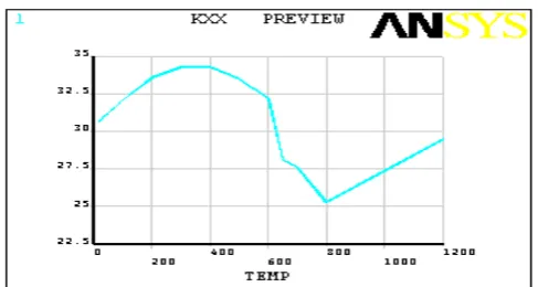
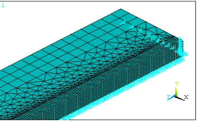
In this paper, the size of simplified half geometric model is 500 mm × 75 mm × 16 mm, as shown in Figure 1. In thermal simulation, three-dimensional thermal entity unit SOLID70 and units SOLID90 in ANSYS software were chosen, in weld area , in order to convenient unit selection and heat load applied next, the unit mesh grid hex-ahedron was selected. The meshed finite element model is shown in Figure 2. In nu-merically simulate, the values of thermal physical parameters change with temperature, The interpolation method was used to determine the values of thermal physical prop-erty parameters at high temperature, the part of the curves in thermal and physical properties are shown in Figure 3 and Figure 4. The boundary conditions are estab-lished as following: the room temperature is 30˚C, in order to prevent the rigid dis-placement, the corresponding displacement constraints of the steel plate was imposed along the weld line, the model of respectively applied convective heat transfer boundary
Table 1. The chemical components of 10Ni3CrMoV test steel (W/%).
Elements C Si Mn Cr P S shrinkage/% Elongation/% Section
Figure 1. Geometric model.
Figure 2. Finite element mesh model.
Figure 3. Density changing curve with temperature.
[image:3.595.255.494.389.523.2] [image:3.595.252.496.554.684.2]and displacement constraints on finite element model are shown in Figure 5 and Fig-ure 6.
2.3. The Heat Source Model
Double ellipsoid heat source model is more suitable for the simulation of fusion weld-ing process with the characteristic of width and deep weldweld-ing pool [3] [8]. So in this ar-ticle, the penetration type double ellipsoid heat source model was chosen to numerical calculation temperature field of double wire welding. The mathematic model of internal heat source is shown in Figure 7, the energy distribution coefficient of the before and after half of ellipsoid set are ff and fr respectively, and the ff + fr = 2. Heat flux
[image:4.595.277.472.250.367.2]distribu-tion funcdistribu-tion is following Formulas (1) and (2).
[image:4.595.277.473.400.520.2]Figure 5. Surface convection boundary model.
Figure 6. Displacement constraints model.
[image:4.595.245.501.547.686.2](
)
22 22 22 11
6 3 3 3 3
, , , f i exp exp exp
fi
i i i
i i i
f Q x y z
q x y z t
a b c
a b c
π π
= − − −
(1)
(
)
22 22 222 2
6 3 3 3 3
, , , r i exp exp exp
ri
i i i
i i i
f Q x y z
q x y z t
a b c
a b cπ π
= − − −
(2)
Among them, the characteristic parameters such as aij, bi, ci (i = 1, 2; j = 1, 2) are
re-lated to the shape of molten pool, desirable different values and independent of each other, by the adjusting of a, b, c parameters, we can adjust the temperature field simula-tion. The arc energy distribution coefficient of the front (ff) and rear (fr) were ff = 0.48,
fr = 1.52.
2.4. Numerical Simulation Specification of Double Wire Welding
Because of the effect of moving welding heat source, the temperature of spot in the workpiece changing with time, called the point of welding thermal cycle. Influence of welding thermal cycle curve parameters mainly includes electric arc voltage (U), as well as double wire welding current(I), welding speed (ν), distance (L) between the two wires. And heat flow calculation and load the program were designed and published in my literatures [1] and [2].
The total heat input E(KJ/cm) of double wire submerged arc welding calculation ex-pression is: E = η(U1I1 + U2I2)/ν, to the double wire submerged arc welding (
η
), it istaken above 0.8 [3] [8]. The fluctuations of voltage U is from negative 5V to positive 5V, current amplitude is from plus to minus 10A, the welding speed was taken 60, 80 and 100 cm/min. According to the different combinations of U1, I1, and U2, I2 and ν, the
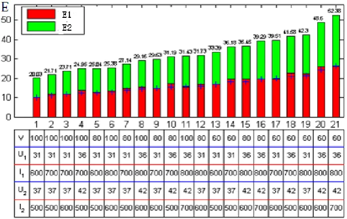
E1, E2 and E can be taken different values, as shown in Figure 8. From the diagram,
[image:5.595.199.549.467.688.2]dif-ferent welding parameters can get 21 sets of E values, the biggest E value is 52.33 KJ/cm,
the smallest E value of 20.03 KJ/cm; And, the heat input value of frontal arc (E1) and
back arc (E2) are different, The length of red, green histogram are respectively shown
the value of the heat input of before and after the arc. The position of blue plus sign is shown the average value of E, when it landed in the red areas indicating E1 > E2, fell on the green area indicating the E1 < E2. Therefore, based on the 21 sets of different
weld-ing parameters and double wire spacweld-ing, the weldweld-ing temperature field is simulated, and the relationship of the heat input E and double wire spacing L with the thermal cycle characteristic parameters were analyzed. Also, the double wire distance L affects the overall welding energy distribution.
3. Numerical Simulation Results
3.1. The Test Results Compared with the Simulation Results
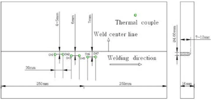
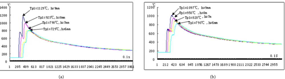
In simulation and test, the model size is the same of 500 × 75 × 16 (mm), the welding parameters (L is constant 60 cm) is been chosen as shown in Figure 8, the simulation is validated by experimentation and the direct measurement of the temperature field with thermocouples,the layout of thermocouples in test is shown in Figure 9. As a result,
the test result is shown in Figure 10(a), the molten pool is formed as shown in Figure 11 (take higher than 1500˚C area as molten pool section) in the simulation, both of them are independent molten pool in the simulation and test, and the size error is within 5%.
3.2. Location Selection in Result Analysis
[image:6.595.196.553.516.686.2]According to the actual welding seam size and the finite element model, in order to convenient analyses, the taken points in finite element nodes are shown in Figure 11. As shown in Figure 12, the points O is located weld center line, the x axis is shown along the width of the weld, the y axis is shown along symmetry plane in the penetra-tion weld seam. By the analysis of the representative points of the thermal cycle, it can get the laws of the double wire welding thermal cycle.
(a)
(b)
[image:7.595.234.518.73.304.2] [image:7.595.195.549.349.483.2]Figure 10. The measured molten pool and the thermal cycle. (a) Molten pool; (b) The welded joint and the thermal cycle.
Figure 11. Molten pool topography of L = 60 mm.
Figure 12. The selected point of weld cross-section.
4. Analysis of Numerical Simulation
[image:7.595.304.447.517.591.2]ac-cording the specification 2 in Figure 8 at wire spacing L = 60 and 100 (mm) the simu-lation of welding temperature field are shown in Figure 13. The correctness of the cal-culation are examined by the measured values of special point by using thermocouple, such as shown in Figure 14, for the error in 5%, the simulation results is effective.
4.1. The t8/5 at Same Wire Spacing
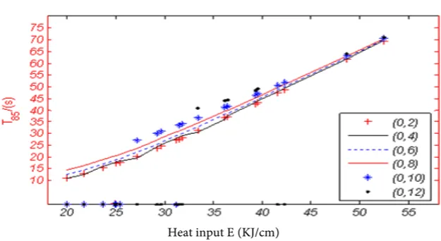
In order to study the effect of heat input E on t8/5 and Tp, The values (L = 60 mm) of t8/5
and Tp of each special points along penetration direction were statistics, shown in Fig-ure 15 and FigFig-ure 16. From FigFig-ure 15, we can see that t8/5 is significant positive
corre-lation with heat input E, and with the increase of heat input E the values of t8 /5 are
clos-er. From Figure 16, with the heat input increased, Tp increase too, but the correlation is not obvious.
4.2. The Tp along Depth and Width of Molten Pool
With different heat input E and different double wire spacing L, how about the law of the peak temperature (Tp)? Peak temperature (Tp) of butt welding plate is unfavorable to the microstructure. The following analysis mainly is to find out law of Tp.
[image:8.595.47.552.339.490.2] [image:8.595.52.551.536.675.2](a) (b)
Figure 13. Double wire welding temperature field. (a) Temperature field (L = 60 mm); (b) Temperature field (L = 100 mm).
(a) (b)
Heat input E (KJ/cm) Figure 15. Variation trend of t8/5 to heat input E.
[image:9.595.215.533.261.413.2]Heat input E (KJ/cm) Figure 16. Variation trend of Tp to heat input E.
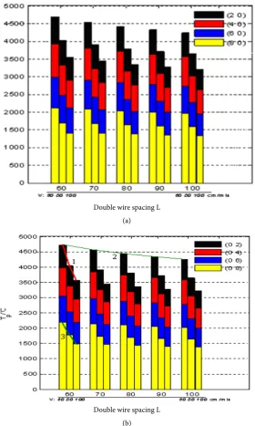
4.2.1. The Tp under Different Double Wire Spacing L
Double wire spacing L (a)
[image:10.595.233.514.69.537.2]Double wire spacing L (b)
Figure 17. Histogram of Tp. (a) Tp of direction depth of molten; (b) Tp of direction of width.
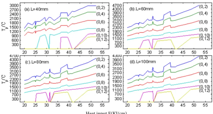
4.2.2. The Tp under the Different Heat Input E
With double wire spacing L (50 mm), along penetration direction, the variation of Tp to heat input E is shown in Figure 18. The proportion of E1 to E2 could be found in
Figure 8: covered several sets (such as 1, 3, 9, 13) of E1 < E2 and the other sets of E1 > E2. We can see that the Tp is not always rising with the increasing of the heat input E, Tp is more closely related to E1 than to E2.
Heat input E(KJ/cm)
Figure 18. The curve of Tp with E under the different spacing.
sensitive factor than E2.
5. Conclusions
(1) Along the points of further from the center of the heat source, the peak tempera-ture (Tp) is lower, the t8/5 constantly is increasing. while the double wire spacing L only
have affect on the peak temperature (Tp), almost less affect t8/5. Therefore, it is effective
method by the mean of increasing the double wire spacing (L) to reduce the peak tem-perature (Tp) without changing the t8/5. On the one hand, we can prevent
microstruc-ture of HAZ from burnt, on the other hand, we can guarantee the microstrucmicrostruc-ture transformation of weld fusion line by control cooling process.
(2) By the secondary development of ANSYS, the thermal field of double wire weld-ing was simulated, the part laws of thermal cycle of double wire weldweld-ing was found. We can improve the microstructure and mechanical properties by the way of adjusting weld process parameters.
Acknowledgements
This work was partly supported by the “Hubei Province Education Department youth project (No.Q20123001). Hubei province natural science foundation of China (No.2014 CFB 177), Dr. Field introduced project (No.11yjz01R), Field introduced project (2015A05)”.
References
[1] Yang, X.Z., Tang, Z.M., Yu, S.F., et al. (2010) About the Calculation of Double Wire Weld-ing Temperature Field of Improvement Algorithm Program Design. Journal of Welding, 53-56.
and Technology, 101-104.
[3] Mo, C.L., Qian, B.N., Guo, X.M., et al. (2001) The Research Progress of Welding Heat Source Computing Model. Journal of Welding, 6, 94-97.
[4] Zhao, P.C., Wu, C.S. and Zhang, Y.M. (2004) Numerical Simulation of the Dynamic Char-acteristic of Weld Pool Geometry with Step Changes of Welding Parameters. Modeling and Simulation in Materials Science and Engineering, 765-780.
[5] Wu, C.S., Chen, J. and Zhang, Y.M. (2007) Numerical Analysis of Both Front- and Back-Side Deformation of Fully-Penetrated GTAW Weld Pool Surfaces. Computational Materials Science, 4, 635-642.
[6] Turna, M., Taraba, B., Ambroz, P., et al. (2011) Contribution to Numerical Simulation of Laser Welding. Physics Procedia, 12, 638-645.
[7] Ranjbarnodeh, E.,Kokabi A.H. and Fischer, A. (2011) Effect of Welding Parameters on Re-sidual Stresses in Dissimilar Joint of Stainless Steel to Carbon Steel. Journal of Materials Science, 46, 3225-3232.
[8] Eagar, B.W. and Tsai, N.S. (2012) Temperature Fields Produced by Traveling Distributed Heat Sources. Welding Research Supplement.
Submit or recommend next manuscript to SCIRP and we will provide best service for you:
Accepting pre-submission inquiries through Email, Facebook, LinkedIn, Twitter, etc. A wide selection of journals (inclusive of 9 subjects, more than 200 journals)
Providing 24-hour high-quality service User-friendly online submission system Fair and swift peer-review system
Efficient typesetting and proofreading procedure
Display of the result of downloads and visits, as well as the number of cited articles Maximum dissemination of your research work
Submit your manuscript at: http://papersubmission.scirp.org/