item and our policy information available from the repository home page for further information.
Author(s):Ciupala, M.A.; Pilakoutas, K.; Mortazavi, A.A.
Title:Utilisation of fibre reinforced polymer (FRP) composites in the confinement of
concrete
Year of publication:2007
Citation:Ciupala, M.A., Pilakoutas, K., Mortazavi, A.A. (2007) ‘Utilisation of fibre
reinforced polymer (FRP) composites in the confinement of concrete’Proceedings of Advances in Computing and Technology, (AC&T) The School of Computing and Technology 2nd Annual Conference, University of East London, pp.145-150
Link to published version:
UTILISATION OF FIBRE REINFORCED POLYMER (FRP)
COMPOSITES IN THE CONFINEMENT OF CONCRETE
M.A. Ciupala, K. Pilakoutas, A.A. Mortazavi
University of East London, University of Sheffield, Power and Water University of Technology Tehran
m.a.ciupala@uel.ac.uk, k.pilakoutas@sheffield.ac.uk, mraa1350@gmail.com
Abstract: This paper presents an experimental investigation carried out on concrete cylinders confined with fibre reinforced polymers (FRP), subjected to monotonic and cyclic loading. Carbon fibres (CFRP) were used as confining material for the concrete specimens. The failure mode, reinforcement ratio based on jacket thickness and type of loading are examined. The study shows that external confinement of concrete can enhance its strength and ductility as well as result in large energy absorption capacity. This has important safety implications, especially in regions with seismic activity.
1. Introduction:
FRP materials have been extensively used in the last ten years to improve the performance of reinforced concrete members in terms of strength and ductility. The civil engineering community, faced with the increased problem of premature deterioration of traditional construction materials, has sought high performance materials to enhance the safety and to extend service life of the infrastructure applications.
FRP materials offer several advantages with respect to the traditional concrete structures, such as lightness, high stiffness, high strength-to-weight rations and ease of application (Hollaway, 1999).
Several composite jacketing systems have been developed and validated in laboratory or field conditions (Seible, 1997), (Teng et al., 2003), (Karantzikis et al., 2005). One of these systems uses unidirectional carbon fibre sheets wrapped longitudinally and/or transversely in the region which needs retrofitting or strengthening.
This paper presents an experimental investigation carried out on CFRP confined concrete cylinders, subjected to
monotonic and cyclic loading. The carbon fibre sheets are wrapped transversely around concrete cylinders to increase their strength and ductility.
2. Experimental investigation:
2.1. Specimen details, instrumentation and test procedure:
Though the research investigated a large number of cylinders, for brevity this paper will deal with only six FRP confined concrete cylinders (Mortazavi,2002). Carbon fibres (CFRP) were used for the construction of the FRP jackets. The mechanical properties of the fibres are shown in Table 1.
Mechanical properties CFRP
Nominal Thickness tj
(mm) 0.117
Young’s modulus Ej
(MPa) 240000
Ultimate tensile
strength fu(MPa) 3900
Three jacket thicknesses were considered comprising 1,2,3 layers of CFRP material. The diameter of cylinders was 100 mm and the height of cylinders was 200 mm.
A number of five concrete cylinder control specimens with a diameter of 100 mm and a height of 200 mm were cast and cured under the same conditions as the FRP confined concrete specimens. Based on the cylinder test results at the time of testing, the average
concrete strength (fco) was found to be 33
MPa.
All the specimens were instrumented with five 15 mm strain gauges: three strain gauges were attached horizontally at
mid-height of each specimen, 120o apart, to
measure lateral strain and two strain gauges were attached vertically at mid-height, to measure axial strain. In addition to the strain gauges, two other displacement measuring devices were employed to measure the lateral and axial strain, respectively.
The tests were carried out using a servo-controlled hydraulic actuator with a capacity of 1000 kN. The specimens were labelled as follows: WCL-n, where W stands for wrapping, C denotes the confinement material - Carbon, L is the number of layers of the FRP jacket and n represents the sample number.
Some of the specimens were tested under uniaxial monotonic compression loading and some of them were tested under uniaxial cyclic loading, as shown in Table 2.
2.2. Failure mode:
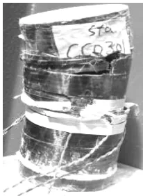
The failure of all the specimens confined with CFRP jackets was sudden and occurred in an explosive manner.
Almost all of the CFRP jackets failed at different locations and a small rupture in the jackets induced complete failure of the
specimen, as shown in Fig.1. In vast majority of cases, the top and bottom part of the samples remained undamaged and hence did not deteriorate during failure. In general, the specimens tested under cyclic load experienced more damage than those tested under monotonic load.
Specimens
/Loading CFRP
Monotonic
WC1-1,
WC1-2 WC2-1, WC3-1
[image:3.595.307.524.218.327.2]Cyclic WC2-2, WC3-2
Table 2 Testing program
2.3. Stress-strain behaviour:
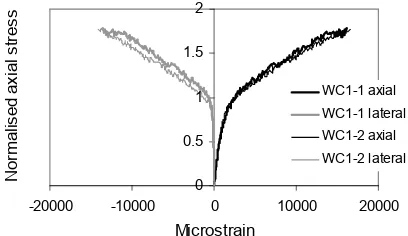
In the case of specimens 1 and WC1-2, the ultimate compressive strength of the confined concrete increased by about 75% of that of the plain (unconfined) concrete,
co
f , as shown in Fig.2. The normalised
axial stress is defined as the ratio of
co cl f
f / , where fcl is the axial
compressive strength of the confined concrete.
[image:3.595.359.462.512.653.2]0 0.5 1 1.5 2
-20000 -10000 0 10000 20000
[image:4.595.87.291.118.236.2]Microstrain N or m alis ed a xi al st res s WC1-1 axial WC1-1 lateral WC1-2 axial WC1-2 lateral
Fig. 2 Stress-strain curves for WC1 specimens The axial strains have positive values whilst the lateral strains have negative values. At failure, the jacket strength was well mobilised in both specimens. The lateral strain in both cases was around
14000µε.
Specimens WC2-1 and WC2-2 appeared to have developed the full capacity of the CFRP jacket and both of them exhibited an ultimate compressive strength of about
2.7fco. Fig.3 shows the normalised axial
stress versus the lateral and axial strain for the WC2 specimens.
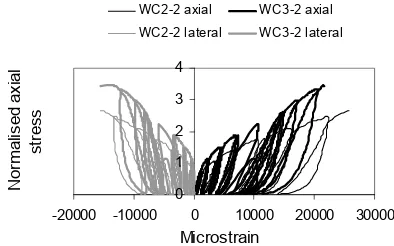
Samples WC3-1 and WC3-2 showed an ultimate compressive strength of about
3.5fco. At failure, in the cyclic test, the
full capacity of the jacket was mobilised whilst in the monotonic test the specimen
failed at around 14500µε, as presented in
Fig.4. 0 0.5 1 1.5 2 2.5 3
-30000 -20000 -10000 0 10000 20000 30000
Microstrain N or m alis ed ax ial st re ss WC2-1 axial WC2-1 lateral WC2-2 axial WC2-2 lateral
Fig. 3 Stress-strain curves for WC2
specimens 0 0.5 1 1.5 2 2.5 3 3.5 4
-30000 -20000 -10000 0 10000 20000 30000
Microstrain N or m alis ed ax ial st re ss WC3-1 axial WC3-1 lateral WC3-2 axial WC3-2 lateral
Fig. 4 Stress-strain curves for WC3 specimens
2.4. Volumetric strain:
The normalised axial stress and normalised axial/lateral strain were plotted versus the volumetric strain. The normalised axial
strain is expressed as εcl /εco and the
normalised lateral strain is defined as
cor cr ε
ε / , where εcl and εcr are the
average axial and lateral strains in the
confined concrete and εco and εcor are the
average axial and lateral strains in the
unconfined concrete (εco =0.002and
001 . 0 = cor ε ).
The volumetric strain is defined as
o
o V
V
V )/
( − , where Voand V are the initial
and final volume of concrete, respectively. Fig.5 shows the relationship between the normalised axial stress and the volumetric strain for WC1-1 and WC1-2 specimens. It can be noted that WC1-1 appears to be less damaged than WC1-2, at similar levels of axial load. Both samples show a similar behaviour as they developed more or less the same volumetric strain at failure. The maximum contraction of the concrete core for WC1-1 and WC1-2 was reached at about
co
f and 0.8 fco, respectively. The
[image:4.595.314.524.118.247.2]due to cracking is almost linear, as shown in Fig.6.
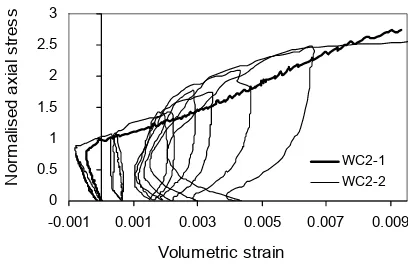
In the case of the WC2-1 and WC2-2 specimens, the volumetric expansion of the concrete core started when the compressive strength of the unconfined
concrete,fco, was reached, as shown in
Fig.7. Although both specimens showed a ductile behaviour, WC2-2 exhibited a larger amount of contraction at the initial stages and a larger amount of expansion in the area of unstable crack propagation. As presented in Fig.8, the relationship between the axial and lateral strain and the volumetric strain for the monotonic loading is almost quasi-linear.
At failure, specimen WC3-1 had an expansion much less than that of specimen WC3-2, as presented in Fig.9.
Volumetric strain 0
0.5 1 1.5 2
-0.0015 0.0015 0.0045 0.0075 0.0105
N
or
m
alis
ed ax
ial
st
re
ss
[image:5.595.85.293.391.522.2]WC1-1 WC1-2
Fig. 5 Normalised axial stress versus volumetric strain for WC1 specimens
Volumetric strain 0
3 6 9 12 15
-0.0015 0.0015 0.0045 0.0075 0.0105
N
or
m
alis
ed s
tr
ain
WC1-1 axial WC1-1 lateral WC1-2 axial WC1-2 lateral
Fig. 6 Normalised strain versus volumetric strain for WC1 specimens
Volumetric strain 0
0.5 1 1.5 2 2.5 3
-0.001 0.001 0.003 0.005 0.007 0.009
N
or
m
alis
ed ax
ial
st
re
ss
WC2-1 WC2-2
Fig. 7 Normalised axial stress versus volumetric strain for WC2 specimens
The contraction point of concrete reached
its maximum value at fco and 0.8 fco for
WC3-2 and WC3-1, respectively. As shown in Fig.10, although the normalised axial strain values are higher for WC3-2 than WC3-1, the values of the normalised lateral strains seem to be similar for both samples. Unlike the WC2 specimens, the normalised axial strain in WG3-1 throughout loading is lower than the normalised lateral strain in the contraction area. This is not the case with specimen WC3-2, as it was noted in Fig.10.
3. Discussion of results
The results of the experimental work are summarised in Figs. 11 and 12.
Volumetric strain 0
4 8 12 16
-0.001 0.001 0.003 0.005 0.007 0.009 0.011
N
or
m
alis
ed s
tr
ain
WC2-1 axial WC2-1 lateral WC2-2 axial WC2-2 lateral
[image:5.595.314.519.568.690.2]Volumetric strain 0 0.5 1 1.5 2 2.5 3 3.5
-0.001 0.003 0.007 0.011
[image:6.595.316.513.113.236.2]N or m alis ed ax ial s tr es s WC3-2 WC3-1
[image:6.595.85.292.124.257.2]Fig. 9 Normalised axial stress versus volumetric strain for WC3 specimens
Fig.11 shows the normalised axial stress for the CFRP confined specimens under monotonic loading and Fig.12 shows the normalised axial stress for the CFRP confined specimens under cyclic loading.
Volumetric strain 0 3 6 9 12 15
-0.001 0.003 0.007 0.011 0.015
[image:6.595.85.292.388.517.2]N or m alis ed s tr ai n WC3-1 axial WC3-1 lateral WC3-2 axial WC3-2 lateral
Fig. 10 Normalised strain versus volumetric strain for WC3 specimens
0 1 2 3 4
-20000 -10000 0 10000 20000 30000
Microstrain N or m alis ed a xia l st re ss
WC1-2 axial WC2-1 axial WC3-1 axial WC1-2 lateral WC2-1 lateral WC3-1 lateral
Fig. 11 Normalised axial stress for CFRP confined specimens under monotonic loading
0 1 2 3 4
-20000 -10000 0 10000 20000 30000
Microstrain N or m alis ed ax ial st re ss
WC2-2 axial WC3-2 axial WC2-2 lateral WC3-2 lateral
Fig. 12 Normalised axial stress for CFRP confined specimens under cyclic loading
An enhancement of the concrete strength
of 3.5 fco is noted for both the monotonic
and cyclic loading.
The stress-strain response of all specimens under cyclic loading is nonlinear, with a parabolic shape, up to failure.
The energy dissipation during the unloading and reloading cycles is considerable for all the FRP confined concrete specimens. Significant plastic strains after unloading are also noticeable. No stiffness degradation upon reloading was observed.
The stress-strain relationship for the monotonic loading may serve as an envelope for cyclic loading.
4. Conclusions:
[image:6.595.85.287.566.688.2]Depending on the stiffness and strength of the confining material, both the ductility and the concrete strength could increase under cyclic loading. This has important safety implications, especially in regions with seismic activity.
5. References:
Karantzikis M., Papanicolaou C.G., Antonopoulos C.P., Triantafollou T.C., “Experimental Investigation of Nonconventional Confinement for Concrete
Using FRP”, Journal of Composites for
Construction, ASCE, 2005, Vol. 9, No. 6, pp. 480-487.
Mortazavi A.A., Behaviour of concrete
confined with lateral pre-tensioned FRP, PhD Thesis, The University of Sheffield, UK, 2002.
Seible F., Prietsley M.J.N., Hegemier G.A., Innamorato D., “Seismic retrofit of RC columns with continuous carbon fiber
jackets”, Journal of Composites for
Construction, ASCE, 1997, Vol. 1, No. 2, pp. 52-62.
Teng M.H., Sotelino E.D., Chen W.F., “Performance Evaluation of Reinforced Concrete Bridge Columns Wrapped with
Fiber Reinforced Polymers”, Journal of