A STUDY ON INDUSTRIAL COMMUNICATION
NETWORKING: ETHERNET BASED IMPLEMENTATION
HAIRULZAWAN HASHIM
ZAINAL ALAM HARON
INTERNATIONAL CONFERENCE ON INTELLIGENT AND
ADVANCED SYSTEMS (ICIAS2007)
25 - 28 NOVEMBER 2007
A Study on Industrial Communication Networking:
Ethernet Based Implementation
H a i r u l a z w a n H a s h i m a n d Z a i n a l A l a m H a r o n F a c u l t y of Electrical a n d E l e c t r o n i c E n g i n e e r i n g ,
Universiti T u n H u s s e i n O n n M a l a y s i a , 8 6 4 0 0 Parit Raja, B a t u Pahat, J o h o r , M a l a y s i a .
Abstract- Recent enhancement of the industrial
communications and networking are possible to apply in
Ethernet networks system at all levels of industrial
automation, especially in the controller level whereby the
data exchanges in real-time communication is
mandatory. This paper is about a study on the
development of industrial communications network
based on the Ethernet protocol and thus implement it
into Computer Integrated Manufacturing (CIM) system.
The purpose of this paper is to overcome real-time
communication in which the accessibility of data
exchange is very difficult in terms of retrieving data
from other stations and time consuming. The Ethernet
module is installed onto supervisory OMRON PLC to
integrate several of stations in the CIM-70A system
which is located at Robotic Laboratory in Universiti Tun
Hussein Onn Malaysia (UTHM). The workability of this
communication technique is analyzed and compared
with the conventional serial communication which
widely used in automation networking systems. It is
found that, the Ethernet protocol approach through the
communication and integration of CIM system can be
accessed easily and available to be upgraded at the
management and enterprise levels of industrial
automation system.
Keyword: CIM, Ethernet
I. I N T R O D U C T I O N
D a t a c o m m u n i c a t i o n and n e t w o r k i n g m a y b e t h e fastest g r o w i n g t e c h n o l o g y in o u r c u l t u r e t o d a y [ 1 ] . It is e x t e n s i v e l y u s e d in an industrial n e t w o r k t o integrate b o t h office a n d m a n u f a c t u r i n g e q u i p m e n t . D u r i n g t h e last t w o d e c a d e s , t h e industrial c o m m u n i c a t i o n s y s t e m h a v e e v o l v e d at a r a p i d p a c e a n d p a s s e d from t h e traditional serial c o m m u n i c a t i o n t o t h e f i e l d b u s e s . T h e t e r m fieldbus a p p l i e s t o a large family o f t w o - w a y digital c o m m u n i c a t i o n p r o t o c o l s that w e r e specially d e v e l o p e d t o o v e r c o m e t h e p h y s i c a l a n d p e r f o r m a n c e l i m i t a t i o n s of l o w level digital and a n a l o g u e s t a n d a r d [2].
E t h e r n e t , t h e w e l l - k n o w n local a r e a n e t w o r k ( L A N ) s t a n d a r d i z e d b y I E E E has b e e n largely utilized in industrial c o m m u n i c a t i o n . T h e E t h e r n e t n e t w o r k h a v e g a i n e d t h e capability of c o m m u n i c a t i n g in r e a l - t i m e t h u s o p e n i n g a n attractive s c e n a r i o ; i m p l e m e n t a t i o n o f E t h e r n e t at all t h e industrial a u t o m a t i o n levels ( F i g u r e 1).
R e a l - t i m e c o m m u n i c a t i o n h a s b e c o m e s o m e m a j o r issue in a u t o m a t e d m a n u f a c t u r i n g s y s t e m . S o m e p r o b l e m s such as data a n d status m o n i t o r i n g , t r a n s m i s s i o n d a t a size a n d s p e e d , online p r o g r a m e d i t i n g , a n d accessibility o f c o n t r o l l e r a r e e n c o u n t e r e d in c o n v e n t i o n a l serial c o m m u n i c a t i o n n e t w o r k i n g such as in C I M s y s t e m .
Figure 1: Pyramid of industrial automation system.
T h i s p a p e r p r e s e n t s an a p p l i c a t i o n o f E t h e r n e t c o m m u n i c a t i o n in C I M - 7 0 A s y s t e m . T h e objectives o f this project a r e : (i) to d e v e l o p a h a r d w a r e infrastructure o f C I M s y s t e m c o m m u n i c a t i o n n e t w o r k b a s e d o n E t h e r n e t , (ii) t o familiarize a n d t h u s o v e r c o m e r e a l - t i m e c o m m u n i c a t i o n issues so that a l l o w s e a s i e r integration b e t w e e n t h e different stations o f t h e C I M s y s t e m v i a E t h e r n e t unit o n O M R O N C J 1 M P L C , a n d (iii) t o verify a n d v a l i d a t e t h e functionality, feasibility a n d w o r k a b i l i t y o f t h e project.
T h i s p a p e r is o r g a n i z e d as follows: Section II r e v i e w s a n industrial E t h e r n e t c o m m u n i c a t i o n b a c k g r o u n d a n d d e v e l o p m e n t b y d e s c r i b i n g t h e c o n c e p t a n d issues in E t h e r n e t c o m m u n i c a t i o n a s w e l l as m a n u f a c t u r e r offered t e c h n i q u e i.e. O M R O N . Section III p r e s e n t s t h e m e t h o d o l o g y used t o i m p l e m e n t E t h e r n e t b a s e d c o m m u n i c a t i o n in t e r m s o f h a r d w a r e installation a n d software d e v e l o p m e n t . Section I V r e p o r t s on t h e results o b t a i n e d a n d section V c o n c l u d e s t h e p a p e r .
II. E T H E R N E T C O M M U N I C A T I O N N E T W O R K I N G
A. Industrial Ethernet Communication System
R e c e n t l y , t h e r e a l - t i m e industrial n e t w o r k h a s b e c o m e a n i m p o r t a n t e l e m e n t for intelligent m a n u f a c t u r i n g s y s t e m s . E s p e c i a l l y , as t h e s y s t e m s a r e r e q u i r e d t o b e m o r e intelligent a n d flexible, t h e s y s t e m s s h o u l d h a v e m o r e field d e v i c e s such as s e n s o r s , a c t u a t o r s , a n d controllers. A s t h e n u m b e r o f field d e v i c e s in m a n u f a c t u r i n g s y s t e m s g r o w s a n d t h e functions o f t h e s y s t e m n e e d t o b e m o r e intelligent, t h e s e d e v i c e s n e e d t o e x c h a n g e t h e r a p i d l y i n c r e a s i n g a m o u n t o f d a t a a m o n g t h e m .
n e e d e d b y field levels. R e c e n t l y , n e w i m p r o v e m e n t s in d a t a transfer s p e e d a n d t h e introduction o f s w i t c h e s p r a c t i c a l l y h a v e o v e r c o m e limits d u e t o n o n - d e t e r m i n i s m o f C S M A / C D p r o t o c o l s [3]. Several E t h e r n e t c o m p a t i b l e p r o t o c o l s h a v e b e e n p r o p o s e d t o s u p p o r t r e a l - t i m e traffic [ 4 ] . I m p l e m e n t i n g E t h e r n e t e v e n at t h e lowest level is suitable for a better interface t o t h e l a s t - g e n e r a t i o n P L C s [ 5 ] , as S o f t - P L C , a l l o w i n g t h e r e u s e o f e x i s t i n g infrastructures.
I n d e p e n d e n t l y from t h e c o m m u n i c a t i o n m o d e l , a r e a l -t i m e p r o -t o c o l b a s e d on E -t h e r n e -t s u p p o s e d -t o h a v e be-t-ter p e r f o r m a n c e t h a n t h e currently a v a i l a b l e fieldbuses. T h i s assertion a c c o u n t for t w o o p p o s i t e issues w h i c h are t h e t r a n s m i s s i o n s p e e d a n d t h e c o m m u n i c a t i o n efficiency [ 6 ] ,
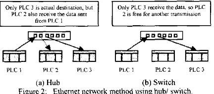
In c r e a t i n g an E t h e r n e t n e t w o r k , t h e r e a few b a s i c d e v i c e s from t h e E t h e r n e t interface on t h e e q u i p m e n t t o t h e h u b s / s w i t c h e s that tie it all t o g e t h e r . A n y e q u i p m e n t c o n n e c t e d to an E t h e r n e t n e t w o r k m u s t h a v e a n E t h e r n e t p o r t that t h e n e t w o r k cable p l u g s into w h i c h often c a l l e d N e t w o r k Interface C a r d ( N I C ) . In industrial P L C s , t h e interface is built into a p l u g - i n m o d u l e like E t h e r n e t unit ( E T N - 2 1 ) m a n u f a c t u r e d b y O M R O N . T h i s E t h e r n e t unit is c a p a b l e to o p e r a t e at 100 M b p s . T h e difference b e t w e e n h u b a n d s w i t c h a r e t h e signal will t r a n s m i t t o all station u s i n g h u b w h i l e a switch directs p a c k e t s o n l y t o t h e station for w h i c h it is i n t e n d e d . In o t h e r w o r d s , it s w i t c h e s t h e signal b e t w e e n input a n d o u t p u t p o r t as illustrates in F i g u r e 2 .
B. Application Example
T h e application of E t h e r n e t c o m m u n i c a t i o n s y s t e m w a s i m p l e m e n t e d in this project. T h i s c o m m u n i c a t i o n a p p r o a c h w a s a p p l i e d in C I M s y s t e m i.e. C I M - 7 0 A w h i c h a v a i l a b l e at R o b o t i c L a b o r a t o r y , U T H M . T h e controller used in C I M -7 0 A s y s t e m is O M R O N P L C ( C J 1 M series). S o m e P L C m a n u f a c t u r e r s offer p r o g r a m m a b l e c o n t r o l l e r s w i t h T C P / I P o v e r E t h e r n e t p r o t o c o l built into t h e P L C p r o c e s s o r . T o t h e full a d v a n t a g e of e x i s t i n g t e c h n o l o g y and m i n i m i z e d e v e l o p m e n t effort, it w a s d e c i d e d t o utilize O M R O N p a c k a g e [7-8] for i m p l e m e n t c o m m u n i c a t i o n n e t w o r k i n g b a s e d on Ethernet.
Only PLC 3 is actual destination, but PLC 2 also receive the data sent
Only PLC 3 receive the data, so PLC 2 is free for another transmission
Lffl S3 63 53 Bra En
PLC 2 PLC 3 PLC 2 PLC 3
(a) Hub (b) Switch Figure 2: Ethernet network method using hub/ switch.
III. E T H E R N E T B A S E D C O M M U N I C A T I O N I N C I M - 7 0 A N E T W O R K
T h e r e a r e t w o m a j o r m e t h o d o l o g i e s a p p l i e d in o r d e r t o realize t h e o b j e c t i v e o f t h e E t h e r n e t n e t w o r k installation a n d software d e v e l o p m e n t in C I M - 7 0 E s y s t e m . T h e C I M - 7 0 A is c h a n g e d t o C I M - 7 0 E s y s t e m for d i s t i n g u i s h a b l e p u r p o s e s o that t h e E t h e r n e t n e t w o r k installation a n d software d e v e l o p m e n t will refer t o C I M - 7 0 E s y s t e m . T h e C I M - 7 0 E s y s t e m is m u l t i p l e P L C link u p t h r o u g h E t h e r n e t n e t w o r k i n g w h e r e e a c h P L C station e x c l u d i n g V i s i o n I n s p e c t i o n Station
h a s o n e E t h e r n e t unit a n d a R J 4 5 u n s h i e l d e d t w i s t e d - p a i r ( U T P ) c a b l e is c o n n e c t e d t h r o u g h 1 0 0 B a s e - T X switch.
A. Hardware Installation
T h e b a s i c configuration for E t h e r n e t s y s t e m c o n s i s t s of o n e s w i t c h / h u b to w h i c h n o d e s a r e a t t a c h e d u s i n g t w i s t e d p a i r c a b l e s . T h e h a r d w a r e u s e d a n d installed o n C I M - 7 0 E s y s t e m is s h o w in F i g u r e 3 . T h e s t a n d a r d s a n d specifications a p p l i e d t o t h e c o n n e c t o r s for t h e E t h e r n e t t w i s t e d - p a i r c a b l e s a r e c o n f o r m i n g t o I E E E 8 0 2 . 3 Electrical specifications s t a n d a r d s a n d c o n n e c t o r structure is R J 4 5 8-pin M o d u l a r C o n n e c t o r w h i c h c o n f o r m i n g to I S O 8 8 7 7 . O v e r v i e w o f start u p p r o c e d u r e for E t h e r n e t unit installation is illustrated as F i g u r e 4 .
Conveyor System
ElX
Workstation
HMI ( S C A D A and CX-programmer)
NIC IP: 10.8 69.7
-L> - L >
0
53
A S R S
Automatic Storage and Retrieval System
Unit N o . 1 IP: 10.8.69.11
Station 1
Robot Arm
Unit N o . 2 IP: 10.8.69.12
Station 2 Station 3
Pick and Place Vision Inspection
[image:3.596.210.536.234.682.2]Unit N o . 3 IP: 10.8,69.13
Figure 3: CIM-70E system architecture
Determine the local IP address and address conversion method.
Switch settings: Set the unit and node number.
Mount the Unit to the PLC.
Network installation:
Connect to the network using twisted-pair cable, and turn ON power to the CPU unit
Connecting to the network: Create the I/O tables, connect to Ethernet unit and set
IP address.
Create the routine tables.
Perform unit setup.
Check communications.
[image:3.596.64.280.510.605.2]B. Communications Test
T h e P I N G c o m m a n d sends an e c h o r e q u e s t p a c k e t t o a r e m o t e n o d e a n d r e c e i v e s an e c h o r e s p o n s e p a c k e t t o c o n f i r m t h a t t h e r e m o t e n o d e is c o m m u n i c a t i n g correctly. T h e P I N G c o m m a n d u s e s t h e I C M P e c h o r e q u e s t a n d r e s p o n s e s as illustrated in F i g u r e 5. T h e e c h o r e s p o n s e p a c k e t is a u t o m a t i c a l l y r e t u r n e d b y t h e I C M P . T h i s c o m m a n d is n o r m a l l y u s e d t o c h e c k t h e c o n n e c t i o n s o f r e m o t e n o d e s w h e n c o n f i g u r i n g a n e t w o r k . T h e E t h e r n e t unit a u t o m a t i c a l l y r e t u r n s t h e e c h o r e s p o n s e p a c k e t in r e s p o n s e t o an e c h o r e q u e s t p a c k e t sent b y a n o t h e r n o d e ( h o s t c o m p u t e r or o t h e r E t h e r n e t unit).
Remote Node
PLC (Host computer or Ethernet unit)
Echo request
Ethernet
V
[image:4.597.72.262.198.309.2]Echo response
Figure 5: PING command [8]
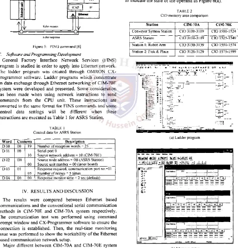
C. Software and Programming Development
G e n e r a l F a c t o r y Interface N e t w o r k S e r v i c e s ( F I N S ) p r o g r a m is studied in o r d e r t o a p p l y into E t h e r n e t n e t w o r k . T h e l a d d e r p r o g r a m w a s c r e a t e d t h r o u g h O M R O N C X -P r o g r a m m e r software. L a d d e r p r o g r a m s w h i c h c o n c e n t r a t e o n d a t a e x c h a n g e t h r o u g h E t h e r n e t n e t w o r k i n g o f C I M - 7 0 E s y s t e m w e r e d e v e l o p e d a n d p r e s e n t e d . S o m e c o n s i d e r a t i o n h a s b e e n m a d e w h e n u s i n g n e t w o r k instructions t o s e n d c o m m a n d s from the C P U unit. T h e s e i n s t r u c t i o n s are c o n v e r t e d t o t h e s a m e format for F I N S c o m m a n d s a n d s o m e c o n t r o l d a t a settings will b e different w h e n t h e s e instructions are e x e c u t e d as T a b l e 1 for A S R S Station.
TABLE 1 Control data for ASRS Station
W o r d Contents Description
D 0 0 00 19 Number of reception words = 25 D 0 1 00
10
Serial port 0
Source network address = 10 (CIM-70E) D 0 2 OB
00
Source node address = 0B (ASRS Station) Source unit number = 00 (inner board) D 0 3 01
05
Response required, communication port no.=01 Number of retries = 5 times
D 0 4 00 00 Response monitor time = 2 sec (default)
IV. R E S U L T S A N D D I S C U S S I O N
T h e results w e r e c o m p a r e d b e t w e e n E t h e r n e t b a s e d c o m m u n i c a t i o n s a n d t h e c o n v e n t i o n a l serial c o m m u n i c a t i o n m e t h o d s in C I M - 7 0 E a n d C I M - 7 0 A s y s t e m r e s p e c t i v e l y . T h e c o m m u n i c a t i o n test w a s p e r f o r m e d u s i n g c o m m a n d p r o m p t w i n d o w a n d C X - P r o g r a m m e r software t o e n s u r e t h e c o n n e c t i o n is e s t a b l i s h e d . T h e n , t h e r e a l - t i m e m o n i t o r i n g issue w a s p e r f o r m e d t o s h o w t h e w o r k a b i l i t y o f t h e E t h e r n e t b a s e d c o m m u n i c a t i o n n e t w o r k s e t u p .
M a j o r different b e t w e e n C I M - 7 0 A a n d C I M - 7 0 E s y s t e m setup is their C I O m e m o r y a r e a c a p a c i t y w h e r e a s t h e r e a r e
2 5 w o r d s a l l o c a t e d for C I M - 7 0 E s y s t e m w h i l e o n l y 10 w o r d s allocated for C I M - 7 0 A s y s t e m ( T a b l e 2 ) . It a l l o w s m o r e i n f o r m a t i o n d a t a t o b e i n t e r c h a n g e s t h r o u g h E t h e r n e t n e t w o r k i n g s u c h as station status, transferring data, E m a i l function, a u t o m a t i c c l o c k a d j u s t m e n t a n d etc.
O n c e a p r o g r a m a n d I/O r o u t i n g t a b l e s o f t h e project n e t w o r k i n g h a s b e e n s e t u p , t h e C X - P r o g r a m m e r software w a s r u n t o m o n i t o r d a t a o n l i n e as s h o w n in F i g u r e 6. All d a t a status; input, o u t p u t a n d m e m o r y area, u p l o a d i n g and d o w n l o a d i n g p r o g r a m , p r o g r a m editing, m o d e c h a n g e s , n e t w o r k r o u t i n g t a b l e s etc. a r e successfully m o n i t o r e d .
[image:4.597.53.539.220.726.2]It is p o s s i b l e t o m o n i t o r t h e v a l u e s w i t h i n P L C a d d r e s s e s from w i t h i n t h e m a i n l a d d e r a n d m n e m o n i c d i s p l a y . F o r each o p e r a n d , a v a l u e is d i s p l a y e d or p o w e r - f l o w is s h o w n t o indicate t h e state o f t h e o p e r a n d as F i g u r e 6 ( a ) .
TABLE 2 CIO memory area comparison
Station CIM-70A CIM-70E
Conveyor System Station CIO 3100-3109 CIO 1500-1524
ASRS Station CIO 3110-3119 CIO 1525-1549
Station 1: Robot Arm CIO 3130-3139 CIO 1550-1574
Station 2: Pick & Place CIO 3120-3129 CIO 1575-1599
I
• E *
a -
-(a) Ladder program
[image:4.597.309.536.256.735.2](b) Memory status
T h e r e s u l t s s h o w e d t h a t t h e m a i n a d v a n t a g e o f u s i n g
E t h e r n e t b a s e d c o m m u n i c a t i o n a s c o m p a r e d to t h e c u r r e n t
serial c o m m u n i c a t i o n is its a b i l i t y t o a c c e s s a s w e l l a s r e a l
-t i m e m o n i -t o r all s -t a -t i o n s a-t a n y p o i n -t .
V . C O N C L U S I O N
In t h i s p a p e r , t h e i m p l e m e n t a t i o n o f E t h e r n e t
c o m m u n i c a t i o n n e t w o r k for C I M s y s t e m w a s p r e s e n t e d . T h e
E t h e r n e t unit w a s i n s t a l l e d at e a c h P L C station a n d s o f t w a r e .
It w a s t h e n s u c c e s s f u l l y d e v e l o p e d a n d p r o v e d t h a t t h e
E t h e r n e t c a n b e e s t a b l i s h e d in C I M - 7 0 A s y s t e m e f f e c t i v e l y
b e t t e r t h a n c o n v e n t i o n a l m e t h o d . T h e u s a g e o f E t h e r n e t
b a s e d c o m m u n i c a t i o n n e t w o r k i n g is e x p e c t e d t o g r o w
r a p i d l y a n d w i d e l y u s e in t h e future.
R E F E R E N C E S
[1] B.A. Forouzan, Data Communications and Networking, 2n d e d , McGraw-Hill, Singapore, 2001.
[2] D.J. Sterling and S.P. Wissler, The Industrial Ethernet Networking
Guide. Thomson-Delar Learning, USA, 2003.
[3] S. Vitturi. "On the use of Ethernet at low level of factory communication systems," Comp. Std. and Interfaces, vol. 2 3 , pp. 267-277, 2001.
[4] C. Szabo, "An Ethernet compatible protocol to support real-time traffic and multimedia applications," Comp. Network ISDN Sys., vol. 29, pp. 335-342, 1997.
[5] C D . Maciel, "TCP/IP networking in process control plants," Comp.
Ind. Eng.. vol. 35, pp. 611-614. 1998.
[6] M. Bertoluzzo, G. Buja and S. Vitturi, "Ethernet network for factory automation," IEEE Int. Symp. on Ind. Electronics, pp. 175-180, 2002. [7] O M R O N Corporation, SYSMAC CS/CJ Series Programmable
Controllers Programming Manual. Kyoto, Japan: cat. no.
W394-E1-08, 2005.
[8] O M R O N Corporation, SYSMAC CS/CJ Series Ethernet Units