Systems Engineering Approach for Modeling An
Organizational Structure
Gary Rushton Visteon Corporation 5850 Mercury Drive Dearborn, MI 48126 USA
Armen Zakarian and Tigran Grigoryan The University of Michigan - Dearborn
2320 Engineering Complex Dearborn, MI 48128 USA
ABSTRACT
An organization is just another type of system. Why not use systems engineering techniques for modeling and development of the organizational structure. Within every organization there are required tasks/functions that interact with each other. Therefore, one may use system engineering techniques to define what the organization is required to do and then develop an organizational structure using some basic design principals, e.g., integration analysis technique to minimize coupling and maximize cohesion between various organizational tasks and functions. In this paper, we illustrate how systems engineering design principles can be used for modeling and analysis of an organization structure.
INTRODUCTION
This paper focuses on the automotive industry. The automotive industry is one of the oldest industries around and unfortunately changes very slowly. For years the automobile has been a collection of parts. In the past, most vehicle functions were easily separated and as new features/functions have been introduced onto a vehicle, new organizations were established to develop these new functions/components. However, in recent years, with the addition of many new electrical/electronic features, the automobile is becoming very complex. Also, the automobile has many subsystems and components that require the same information. This is causing many automotive manufacturers and suppliers to look at the automobile as one system. Some Original Equipment Manufacturer’s (OEM’s) and suppliers believe that designing and sourcing systems can even save money. However, most automotive companies are not organized to design the automobile as one system. Typically, automotive manufacturers and there suppliers are organized by function/component as a result of how these components get purchased. Most automobile manufacturers want to be in control of the system design, especially since they are the ones who are ultimately responsible/liable for the vehicle. To
provide a customer with the best product possible, both the automobile manufacturer and the system supplier have to be partners. Such partnerships will result in delivering higher quality products to the customer and may improve profitability for the automobile manufacturer and system supplier. In most cases, processes, and organizations that execute them, have not been designed using structured approaches, rather they have evolved over time in response to the changing business environment. This changing environment might damage a company, unless it makes a conscious and constant effort to re-organize to accommodate changes in the market needs and technology changes. This paper presents a structured methodology to model an automotive electrical/ electronic (E/E) system supplier, that designs and sells vehicle systems, and uses the tasks/interactions to develop its organizational structure.
ORGANIZATION REQUIREMENTS ANALYSIS
The system supplier also needs to have a vision of the future and be working on advanced technologies and concepts that will meet the user and customer needs. The latter perhaps is one of the most challenging tasks a system supplier is facing, primarily because the technology is changing so rapidly. However, the required development time for a new vehicle design remains unchanged, i.e., 3 to 6 years. The automobile manufacturer typically wants to offer the latest and greatest features to the user, but in many cases they don’t even know what those features are until 2 or 3 years into the vehicle development cycle.
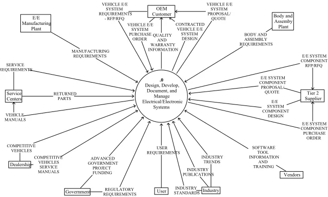
Requirements Model. To capture all of the functions/tasks and interactions required for the system supplier to perform its role, we have developed a Hatley/Pirbhai requirements model [Hatley and Pirbhai 1987] using the TurboCase/Sys software tool from StructSoft Inc. In this study, we have focused on the design, development, documentation, and program management of the vehicle electrical/electronic system (see context diagram in Figure 1). From Figure 1, one may see that the system supplier has to interface with the automobile manufacturer (OEM Customer) for the Request For Proposal/Request For Quote (RFP/RFQ) and purchase order, with the vehicle assembly plant, service center, government, and manufacturing plant for product related requirements. The system supplier also interfaces with dealerships to purchase competitive vehicles, with the user and industry to determine future trends/needs, and with vendors to make sure state of the art software tools are being developed and applied during the design of the vehicle E/E system. It should be noted that the system model developed as part of this paper can be extended to include other basic functions of an organization related to the supplier, employee, investor, and so on. For illustration purposes we restricted our analysis to the design, development, and program management related functions of an automotive system supplier organization.
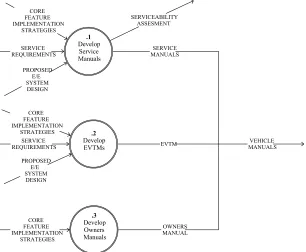
The diagrams within the system model are hiarchical and the child diagram of the context diagram is known as data flow diagram (DFD) 0. DFD 0 is the top level diagram for the system being designed. In this case, DFD 0 in Figure 2 represents all of the high level processes, i.e., functions/tasks, required for the E/E system supplier. These tasks/functions are represented as circles (processes) or double ringed (bolded) circles (primitive processes) on DFD 0 and perform the function identified by there associated name. Six processes on DFD 0 diagram are represented with a circle and can be further decomposed into lower level processes:
Provide Systems Engineering Services Provide Subsystems Engineering Services
Provide Marketing and Sales Services Provide Integration and Test Services Develop Advanced Concepts and Designs Provide Serviceability Analysis
The other four processes in Figure 2 are considered primitive processes (PSPECs) and are represented as double ringed (bolded) circles. These particular primitive processes do not have any associated lower level functions/processes, meaning they do not decompose. The following processes/functions are PSPECs and also perform the function identified by there associated name:
Provide Business Planning Services
Provide Benchmarking and Competitive Analysis Provide Quality and Reliability Analysis
Develop Processes, Methods, Tools, and Training From Figure 2 one may see, many of the processes on DFD 0 have several interactions with each other. Some of the interactions actually interact with lower level functions/processes; which can be seen on the child diagrams.
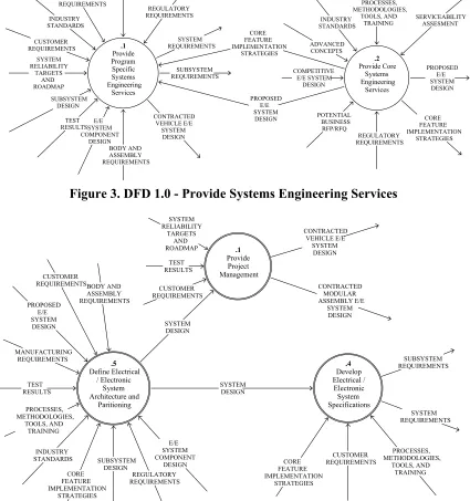
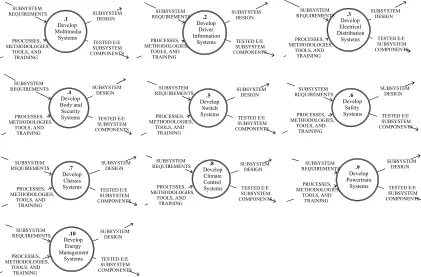
Each non-primitive process on DFD 0 is decomposed to the lowest level processes (see Figures 3 through 10). For example, one may see “Provide Systems Engineering Services” process in Figure 2 is decomposed into two processes in the next level (child), i.e., “Provide Program Specific Systems Engineering Services” and “Provide Core Systems Engineering Services”. The system requirements model captures this decomposition and is shown in Figure 3. Each of the two processes in Figure 3 is further decomposed into lower level PSPECs (see Figures 4 and 5). Similarly, “Provide Subsystems Engineering Services” process in Figure 2 is decomposed into ten different PSPECs in Figure 6. The same functional decomposition approach is used for each of the remaining four processes shown in Figure 2. The data flow diagrams (DFD’s) that capture these decompositions are shown in Figures 7, 8, 9, and 10.
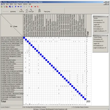
constructed (see Figure 11) [Rushton and Zakarian 2000].
SYSTEMS ORGANIZATION
Design Phase. The interaction (incidence) matrix of primitive processes (tasks) is shown in Figure 11. Each row/column of the matrix in Figure 11 corresponds to the required elementary function/task of the automotive E/E system supplier. Each non-zero entry xij in the
matrix indicates the information or material flow between tasks i and j, and the direction of the link (flow) is from j to i. A Clustering technique is used to determine how best to group those processes to form an organizational structure.
Clustering techniques are used to group objects into homogenous clusters based on object features. Clustering is also a generic name for a variety of mathematical methods that are used to find natural groupings in a given object/data set. Cluster analysis has been widely used for solving various engineering problems, e.g., design of modular systems, group technology, pattern recognition, image sequence coding, etc. The technique has also been widely used in the natural sciences (see Sneat and Sokal 1973) and increasingly in social sciences.
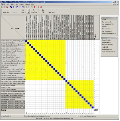
In this paper, software that uses a new clustering algorithm for development of modular systems is used to cluster the interaction (incidence) matrix of the organization and to identify an organizational structure. The new algorithm can be used for clustering both binary and non-binary (weighted) matrices [see Zakarian and Rushton 2001]. From the function - function (n × n) incidence matrix the algorithm first creates n clusters. Once initial clusters are obtained the algorithm continuously improves the initial solution by moving the bottleneck elements to a cluster, if such an assignment improves the quality of the solution, i.e., maximizes interactions within the clusters (groups) and minimizes interactions between the groups. The clustering algorithm applies some basic systems engineering design principals, i.e., minimize coupling and maximize cohesion. Running the clustering algorithm on the system supplier interaction (incidence) matrix (Figure 11) produces the clustered matrix shown in Figure 12.
One may see in Figure 12, that the objective of the clustering algorithm is to group elementary tasks/ functions of the organization such that, the interactions between the tasks in the same group is as strong as possible and interactions of tasks between the groups is as “weak” as possible. The underlying premise is that by optimizing information and material flow between the tasks will produce an organizational structure that is lean, can more efficiently meet organization
requirements captured in the system model, and can better respond to the changing business environment. It should be emphasized that once the organizational structure is identified from the clustering matrix, one may use system dynamics [see Richardson and Pugh 1981] or stream analysis [see Porras 1990] techniques to perform a failure mode and effect analysis for the organizational structure.
Organizational Structure. The matrix shown in Figure 12, includes two clusters. For the purpose of this paper, the two clusters represent two departments within an automotive E/E system supplier organization (see Figure 13). One department performs the system design, subsystem design, testing, sales, and development of processes, methods, and tools functions. The other department performs the benchmarking, business planning, advanced development, marketing, quality/reliability, and core system activities. As can be seen in Figure 12, the majority of the interactions between each of the tasks/functions are grouped within a given cluster (department). In other words, the organizational structure developed, maximizes interactions between functions within a department and minimizes interactions between departments.
CONCLUSION
An organization is just another type of system. Therefore, one may consider using systems engineering techniques when developing an organizational structure. This paper presents a methodology that uses systems engineering design principles and allows an automotive E/E system supplier to model and develop its organizational structure. A systems requirements model was developed to identify the tasks, inputs, and outputs required to perform each particular job function. Once those tasks/functions were identified and modeled, an interaction (incidence) matrix was developed. A clustering algorithm was then used to cluster the tasks/functions of an automotive E/E system supplier and identify an organizational structure. The clustering algorithm used in this paper, grouped the tasks/functions in an interaction matrix by minimizing coupling between tasks and maximizing cohesion among the tasks. As demonstrated in this paper, an organization is just another type of system and systems engineering techniques can be used when developing an organizational structure.
ACKNOWLEDGEMENTS
REFERENCES
Hatley, D., Hruschka, P., and Pirbhai, I., Process For System Architecture and Requirements Engineering. Dorset House, New York, 2000
Porras, J. I. (1990), Stream analysis: A powerful way to
diagnose and manage organizational change.
Addison Wesley, Menlo Park, CA.
Richardson, G. P. and Pugh, A. L. (1981), Introduction
to system dynamics modeling with DYNAMO.
Productivity Press, Cambridge, MA.
Rushton, G. and Zakarian, A., "Modular Vehicle Architectures: A Systems Approach", Proceedings of the Tenth Annual International Symposium of the International Council on Systems Engineering, Minneapolis, MN, July 16-20, 2000, pp 29-35. Sneat, P. H. and Sokal, R. R., Numerical Taxonomy.
San Francisco, CA. W. H. Freeman, 1973.
Zakarian, A. and Rushton, G. J., "Development of
Modular Electrical Systems," IEEE/ASME
Transactions on Mechatronics, Vol. 6 No. 4, pp. 507-520, 2001.
BIOGRAPHY
Gary Rushton has over 17 years of commercial and military electrical/electronic systems engineering experience. He has an MS in Automotive Systems Engineering from the University of Michigan. He is currently working as an electrical/electronic systems engineer specialist with Visteon Corporation. As an engineer with Visteon Corporation, he has worked on audio software, subsystem product development/design, diagnostics, vehicle system architectures, and cockpit systems design. Previously, with General Dynamics, he worked on avionics systems for the F-16 and vetronics systems for the Abrams M1A2 tank. ([email protected]).
Armen Zakarian received his B.S. degree in mechanical engineering from Yerevan Polytechnic University, Yerevan, Armenia, his M.S. degree in industrial and systems engineering from the University of Southern California, Los Angeles, California and his Ph.D. degree in industrial engineering from the University of Iowa, Iowa City, Iowa, in 1997. He is an Assistant Professor of Industrial and Manufacturing Systems Engineering at the University of Michigan - Dearborn. He has published papers in journals sponsored by ASME, IEEE and IIE societies. His research interests include development of integrated products and systems, quantitative/qualitative analysis of process models, and modeling and analysis of manufacturing systems. ([email protected]).
Tigran Grigoryan received his B.S. degree in applied mathematics and computer science from Yerevan State University and his M.S. degree in applied mathematics from Yerevan State Engineering University. He is currently M.S. degree candidate in Industrial and
Figure 1. Automotive E/E System Supplier Context Diagram
Figure 2. DFD 0 – Design, Develop, Document, and Manage Electrical/Electronic Systems
[image:5.612.139.477.335.686.2]Figure 3. DFD 1.0 - Provide Systems Engineering Services
Figure 4. DFD 1.1 - Provide Program Specific Systems Engineering Services
Provide Program Specific Systems Engineering
Services
.1
Provide Core Systems Engineering
Services
.2
CUSTOMER
REQUIREMENTS ADVANCEDCONCEPTS
PROCESSES, METHODOLOGIES,
TOOLS, AND TRAINING
PROCESSES, METHODOLOGIES,
TOOLS, AND
TRAINING SERVICEABILITYASSESMENT
SYSTEM RELIABILITY
TARGETS AND ROADMAP
SUBSYSTEM DESIGN
COMPETITIVE E/E SYSTEM
DESIGN
POTENTIAL BUSINESS RFP/RFQ E/E
SYSTEM COMPONENT
DESIGN REQUIREMENTSREGULATORY
BODY AND ASSEMBLY REQUIREMENTS MANUFACTURING
REQUIREMENTS
REGULATORY REQUIREMENTS
PROPOSED E/E SYSTEM DESIGN SYSTEM
REQUIREMENTS
SUBSYSTEM REQUIREMENTS
CONTRACTED VEHICLE E/E
SYSTEM DESIGN
INDUSTRY STANDARDS
TEST RESULTS INDUSTRY STANDARDS
PROPOSED E/E SYSTEM DESIGN CORE FEATURE IMPLEMENTATION
STRATEGIES
CORE FEATURE IMPLEMENTATION
STRATEGIES
Provide Project Management
.1
Develop Electrical / Electronic System Specifications
.4
Define Electrical / Electronic
System Architecture and
Paritioning
.5
MANUFACTURING REQUIREMENTS
PROCESSES, METHODOLOGIES,
TOOLS, AND TRAINING TEST RESULTS
TEST RESULTS
SYSTEM RELIABILITY
TARGETS AND ROADMAP
CUSTOMER REQUIREMENTS CUSTOMER
REQUIREMENTSBODY AND ASSEMBLY REQUIREMENTS
INDUSTRY
STANDARDS SUBSYSTEM
DESIGN
REGULATORY REQUIREMENTS
E/E SYSTEM COMPONENT
DESIGN
CONTRACTED VEHICLE E/E
SYSTEM DESIGN
CONTRACTED MODULAR ASSEMBLY E/E
SYSTEM DESIGN
SUBSYSTEM REQUIREMENTS
SYSTEM REQUIREMENTS
CUSTOMER REQUIREMENTS SYSTEM
DESIGN SYSTEM
DESIGN PROPOSED
E/E SYSTEM
DESIGN
PROCESSES, METHODOLOGIES,
TOOLS, AND TRAINING CORE
FEATURE IMPLEMENTATION
STRATEGIES
CORE FEATURE IMPLEMENTATION
[image:6.612.95.520.107.560.2]Figure 5. DFD 1.2 - Provide Core Systems Engineering Services
Figure 6. DFD 1.3 – Provide Subsystems Engineering Services
Develop System Architecture and Partitioning Proposals .1 Define Core Feature Implementation Strategies .2 ADVANCED CONCEPTS INDUSTRY STANDARDS PROCESSES, METHODOLOGIES, TOOLS, AND TRAINING SERVICEABILITY ASSESMENT POTENTIAL BUSINESS RFP/RFQ REGULATORY REQUIREMENTS COMPETITIVE E/E SYSTEM DESIGN ADVANCED CONCEPTS INDUSTRY STANDARDS PROCESSES, METHODOLOGIES, TOOLS, AND TRAINING SERVICEABILITY ASSESMENT REGULATORY REQUIREMENTS COMPETITIVE E/E SYSTEM DESIGN CORE FEATURE IMPLEMENTATION STRATEGIES CORE FEATURE IMPLEMENTATION STRATEGIES PROPOSED E/E SYSTEM DESIGN Develop Multimedia Systems .1 Develop Electrical Distribution Systems .3 Develop Switch Systems .5 Develop Driver Information Systems .2 Develop Body and Security Systems .4 Develop Safety Systems .6 Develop Chassis Systems .7 Develop Climate Control Systems .8 Develop Powertrain Systems .9 Develop Energy Management Systems .10 SUBSYSTEM REQUIREMENTS SUBSYSTEM DESIGN PROCESSES, METHODOLOGIES, TOOLS, AND TRAINING TESTED E/E SUBSYSTEM COMPONENTS SUBSYSTEM
REQUIREMENTS SUBSYSTEMDESIGN
PROCESSES, METHODOLOGIES, TOOLS, AND TRAINING TESTED E/E SUBSYSTEM COMPONENTS PROCESSES, METHODOLOGIES, TOOLS, AND TRAINING SUBSYSTEM
REQUIREMENTS SUBSYSTEMDESIGN
[image:7.612.97.518.304.581.2]Figure 7. DFD 1.5 – Provide Marketing and Sales Services
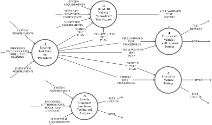
Figure 8. DFD 1.6 – Provide Integration and Test Services
Provide Off Vehicle / Yellowboard
Testing
.1
Develop Test Plans
and Procedures
.2
Provide In Vehicle Testing
.3
Build Off Vehicle / Yellowboard Test Fixtures
.4
Provide Computer Simulation, Testing, and Analysis
.5
SYSTEM REQUIREMENTS
SUBSYSTEM REQUIREMENTS PROCESSES, METHODOLOGIES,
TOOLS, AND TRAINING
TESTED E/E SUBSYSTEM COMPONENTS
SYSTEM REQUIREMENTS
PROCESSES, METHODOLOGIES,
TOOLS, AND TRAINING
SUBSYSTEM REQUIREMENTS
VEHICLE TEST PLAN
YELLOWBOARD TEST PROCEDURES
YELLOWBOARD TEST PLAN YELLOWBOARD
TEST PLAN SYSTEM
REQUIREMENTS
YELLOWBOARD TEST FIXTURE SUBSYSTEM
REQUIREMENTS
VEHICLE TEST PLAN
VEHICLE TEST
PROCEDURES DVPR
DVPR TEST RESULTS
TEST RESULTS TEST
RESULTS
DVPR
Provide Market Research
.1
Sell Products
.2
BUSINESS AND PRODUCT STRATEGY
BUSINESS AND PRODUCT STRATEGY
E/E SYSTEM COMPONENT
PROPOSAL/ QUOTE
VEHICLE E/E SYSTEM PURCHASE
ORDER VEHICLE E/ESYSTEM REQUIREMENTS
- RFP/RFQ USER REQUIREMENTS
COSTED E/E SYSTEM
DESIGN
MARKET RESEARCH
POTENTIAL BUSINESS RFP/RFQ
VEHICLE E/E SYSTEM PROPOSAL/
QUOTE
CUSTOMER REQUIREMENTS
E/E SYSTEM COMPONENT PURCHASE
ORDER
[image:8.612.90.521.382.637.2]Figure 9. DFD 1.9 - Develop Advanced Concepts and Designs
Figure 10. DFD 1.10 - Provide Serviceability Analysis
Investigate, Design, and Develop Next
Generation E/E System Architectures and Strategies .1 Investigate, Design, and Develop Next Generation Wiring Systems and Strategies .3 Investigate, Design, and Develop Smart Connector Systems and Strategies .2 Investigate, Design, and Develop Smart Switch Systems and Strategies .4 Investigate, Design, and Develop Next Generation Energy Management Systems and Strategies .5 ADVANCED GOVERNMENT PROJECT FUNDING QUALITY AND WARRANTY INFORMATION COMPETITIVE E/E SYSTEM DESIGN INDUSTRY TRENDS MARKET RESEARCH INDUSTRY PUBLICATIONS REGULATORY REQUIREMENTS TECHNOLOGY ROADMAPS ADVANCED CONCEPTS INDUSTRY PUBLICATIONS MARKET RESEARCH ADVANCED GOVERNMENT PROJECT FUNDING QUALITY AND WARRANTY INFORMATION COMPETITIVE E/E SYSTEM DESIGN INDUSTRY TRENDS REGULATORY REQUIREMENTS TECHNOLOGY ROADMAPS ADVANCED CONCEPTS INDUSTRY PUBLICATIONS MARKET RESEARCH ADVANCED GOVERNMENT PROJECT FUNDING QUALITY AND WARRANTY INFORMATION COMPETITIVE E/E SYSTEM DESIGN INDUSTRY
TRENDS REQUIREMENTSREGULATORY
TECHNOLOGY ROADMAPS ADVANCED CONCEPTS INDUSTRY PUBLICATIONS MARKET RESEARCH ADVANCED GOVERNMENT PROJECT FUNDING QUALITY AND WARRANTY INFORMATION COMPETITIVE E/E SYSTEM DESIGN INDUSTRY
TRENDS REQUIREMENTSREGULATORY
[image:9.612.158.464.421.673.2]Figure 12. – Cluster Matrix for an Automotive E/E System Supplier Organization
Figure 13. Automotive E/E System Supplier Organization Structure
System Engineering Services Integration and Test Services Subsystem Engineering Services
Sales
Processes, Methods, Tools, and Training Department 1
Benchmarking and Competitive Analysis Business Planning Services Advanced Concepts and Designs
Marketing
Quality and Reliability Analysis Serviceability Analysis Department 2
[image:11.612.139.461.513.676.2]