2019 International Conference on Computer Intelligent Systems and Network Remote Control (CISNRC 2019) ISBN: 978-1-60595-651-0
The Application of High Efficiency and Low Noise
Switching Power Supply in Fiber Optic Gyroscope
Kang Zou, Lei Wang and Xiao-wu Shu
ABSTRACT
For high-precision fiber optic gyro systems, the efficiency and noise in the switching power source limits its application and also affects the system's light source and signal processing circuit, resulting in output errors. The interference mechanism of switching power supply ripple noise on super luminescent diode (SLD) light source and demodulation module in fiber optic gyro system is analyzed. A high-efficiency and low-noise switching power supply based on synchronous rectification is proposed. The power supply uses RC circuit to realize adjustable switching frequency. The push-pull isolation topology, LC filter and LDO regulator circuit are used to achieve constant voltage output with peak-to-peak ripple noise of less than 1mV. The conversion efficiency of the switching power supply is improved by 10%, which provides a high-quality power source for the high-precision fiber optic gyroscope. In the meanwhile, the switching power source for FOG is 5 4 1 cm in size, which is beneficial to the miniaturization of inertial navigation system.
KEYWORDS
Fiber-optic gyroscope, Switching power source, Synchronous rectification, Ripple noise, Conversion efficiency.
INTRODUCTION
Fiber-optic gyroscope (FOG) is an all-solid-state angular velocity sensor based on Sagnac effect. It has the advantages of small size, light weight, high precision, no moving parts, etc.[1-2], and it is widely used in rotary inertial navigation and strapdown inertial navigation system[3]. The inertial navigation system generally provides about 28V DC voltage input, while the analog circuit reference voltage in the fiber optic gyroscope is ±5V, and the digital circuit voltage input is 5V. Therefore, the fiber optic gyroscope used in the inertial navigation system needs a voltage conversion module to convert the input DC voltage into the needed voltage value, while minimizing the impact of the introduction of the power conversion module on the performance of the fiber optic gyro output. The switching power supply is a commonly used voltage converter. The principle is to realize the buck-boost by using the turn-on and turn-off of the transfer device and the charge and discharge of the accumulator in combination with various topologies. Compared with the traditional linear regulator, the switching power supply has the advantages of high efficiency, stability, reliability, isolation and multi-output, and has become an ideal power source for the fiber optic gyroscope in the inertial navigation system.
_________________________________________
Kang Zou, Xiao-wu, Shu, College of Optical Science and Engineering Zhejiang University Hangzhou 310027, China
The main source of noise in the switching power supply is the colored ripple noise introduced during the switching process of the transmission device[4]. The noise has a fixed frequency, and the output voltage value has fluctuations on the order of tens of millivolts. For high-precision fiber optic gyro systems, the magnitude of the weak electrical signal during the digital signal processing is microvolts or even nanovolts. It can be seen that the performance of the high-precision fiber optic gyro has high requirements for noise suppression of the switching power supply.
At present, there are few researches on switching power supplies applied to fiber optic gyroscopes at home or abroad. Zhang Jingpei et al. analyzed the effects of PWM waveform changes and noise caused by switching frequency on the accuracy of medium-precision fiber optic gyroscopes for medium-precision fiber optic gyroscopes[5]; Chen Xian et al. analyzed the spike glitch noise of the switching power supply in high-precision gyro, and proposed and designed a low-noise switching power supply to improve the output performance of the fiber optic gyroscope[6].
Combining with the working principle of high-precision fiber optic gyroscope, this paper theoretically analyzes the interference mechanism of switching power supply ripple noise on super-radiation light-emitting diode (SLD) light source and signal modulation and demodulation module in fiber optic gyroscope, proposes and implements a switching power supply with adjustable switching frequency and synchronous rectification. Experiments show that the switching power supply improves the conversion efficiency compared with the conventional power supply, effectively suppresses the colored ripple noise, and provides an ideal power supply for the high-precision fiber optic gyroscope.
CIRCUIT STRUCTURE OF FIBER OPTIC GYRO SYSTEM
In fiber-optic gyro systems, not only optical devices such as SLD sources, fiber rings, couplers, and Y-waveguides introduce optical noise such as Rayleigh scattering and Kerr effect[7]; at the same time, a large part of the noise in the system comes from the digital signal processing part of circuit structure[8].
As shown in Figure 1, the circuit structure of the fiber optic gyroscope is mainly composed of a power module, a digital signal processing module and a light source module. The switching power supply is used as an external power supply to directly supply power to the SLD light source, the ADC sampling module and the DSP module. Therefore, the switching power supply becomes the front of the fiber optic gyro noise source.
ANALYSIS OF SWITCHING POWER SUPPLY RIPPLE NOISE INTERFERENCE IN FIBER OPTIC GYROSCOPE
[image:3.595.175.409.285.355.2]The noise of the switching power supply is mainly divided into ripple noise and glitch noise, as shown in Figure 2. Ripple noise is a kind of colored noise, which is derived from the process of charge and discharge of energy storage devices such as capacitors and inductors, while glitch noise is an irregular, spectrally complex noise whose amplitude is less fluctuating than ripple noise. This noise can be reduced by low-pass filter circuits, isolated topologies, and replacement of better-performing switching devices. Therefore, this paper analyzes the influence of switching power supply ripple noise on the performance of fiber optic gyroscope from two aspects: SLD light source and signal modulation and demodulation.
Figure 2. Schematic diagram of switching power supply noise.
RIPPLE NOISE INTERFERENCE TO SLD SOURCE
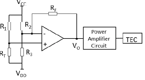
As a common light source for fiber optic gyroscope, super luminescent diode (SLD) has the characteristics of high output power, wide spectral width and short-term coherence, which can effectively suppress parasitic interference and nonlinear Kerr effect, therefore reducing the zero drift of the fiber optic gyro output[9-11]. The output power of the SLD source and the stability of the center wavelength directly affect the accuracy of the fiber optic gyro. The driving current and ambient temperature of the light source directly affect the output optical power and the center wavelength. Therefore, it is necessary to implement the temperature control circuit and the constant current source circuit to ensure the stable output of the SLD light source. The switching power supply supplies power to the above two circuits.
Figure 3. SLD temperature control circuit.
The output voltage of the first stage op-amp is as follows:
2 3 1
2 2 3 1 3
1 2 3 1 3 2
1
o
T
T F T F
F T F
V
R R R R
VCC R R R R R R R R R
VDD R R R R R R R R R
(1)
where, VCC and VDD are positive and negative voltages provided by the switching power supply. In the fiber optic gyroscope, VCC=-VDD, R1=R2=R3=RT0=R0, RT0 is the temperature control resistance at normal
temperature, but due to the switching power supply ripple noise, VCC≠-VDD, assuming positive and negative voltage misalignment errors caused by switching power supply ripple:
1
DD CC
V K V (2)
then the thermistor error:
2 0 0 2 T F K R RK R R
(3)
Therefore, the TEC temperature compensation error introduced by the switching power supply ripple noise will affect the output stability of the light source and ultimately affect the performance of the fiber gyro output.
Figure 4. SLD constant current source circuit.
The constant current value provided by this ciucuit is:
CC DD
V V
I
R
(4)
If the switching power supply provides a positive and negative voltage value ripple noise of 100mV, and the resistance R takes 10Ω, the resulting driving current error is:
100 10 10
V mV
I mA
R
(5)
Therefore, the output optical power and the center wavelength output of the SLD source are unstable, which ultimately affects the precision of fiber optic gyroscope.
RIPPLE NOISE INTERFERENCE ON SIGNAL MODULATION AND DEMODULATION MODULE
The ripple noise of switching power supply is a colored noise with a fixed frequency fw determined by the PWM switch control circuit. For fiber optic gyroscope with square wave modulation, the modulation frequency is:
1 2
m
f
(6) where the transit time τ of the fiber ring is:
Ln c
(7)
L is the total length of the fiber coil, n is the refractive index of the fiber, and c is the speed of light in the vacuum.
demodulation, resulting in large resistance noise in the modem module and finally deteriorate the digital output performance of the fiber optic gyroscope. Therefore, in the design of the switching power supply, the switching frequency can be adjusted and kept away from the modulation and demodulation frequency of the fiber optic gyroscope and its multiplier.
DESIGN AND IMPLEMENTATION OF HIGH EFFICIENCY AND LOW RIPPLE NOISE SWITCHING POWER SUPPLY
The switching power supply in the fiber optic gyroscope has more stringent requirements than the ordinary switching power supply. As mentioned in the previous section, the excessive ripple noise can destroy the output stability of the SLD light source, and the switching frequency will resonate with the modulation and demodulation frequency, thus increasing the circuit noise. Therefore, it is necessary to reduce the output ripple noise of the switching power supply and also adjust the switching frequency to avoid resonance with the modulation and demodulation signal.
The switching power supply acts as a buck module to depress the high voltage input provided by the inertial navigation system into the required value for the fiber optic gyroscope. Since the multi-navigation device works in cooperation in the inertial navigation system, improving the power conversion efficiency can supply more inertial navigation devices and in void large pieces of heat, which will affect the service life of the fiber optic gyroscope.
SWITCHING POWER SUPPLY CONVERSION EFFICIENCY IMPROVEMENT
Switching power supplies usually include PWM switch control modules, MOSFET switch tubes, transformers, rectifier circuits, and filter circuits. The loss of the switching power supply is mainly reflected in two aspects. One is the conduction loss, that is, the current through the MOSFET internal resistance, the transformer coil resistance and the internal resistance of the rectifier diode when the current is transmitted in the circuit; the other is the switching loss, that is, the turn-on and turn-off of the MOSFET switch.
TABLEI.SWITCHINGPOWERSUPPLYLOSSINTHELABORATORY. Device loss value(mW)
transformer 150
MOSFET conduction loss 140
MOSFET switching loss 275
MOSFET drive loss 20
Diode 650
Filter capacitor 42
PWM control chip 105
As can be seen from the above table, the switching power supply loss of the low-voltage output mainly comes from the conduction loss and switching loss of the MOSFET and the voltage drop loss of the rectifier diode.
during the turn-on and turn-off of the MOSFET is reduced, and the corresponding operation state is quickly entered. In the design of this switching power supply, after researching various types of MOSFET of various manufacturers, a MOSFET tube with an on-resistance of 18mΩ, on-time of 8.7ns, and turn-off time of 10ns was finally determined.
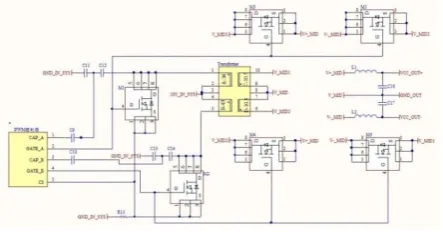
[image:7.595.192.414.330.446.2]For a low-voltage output switching power supply, such as the above 5V output, the unavoidable voltage drop due to the rectifier diode is the most important loss in the switching power supply. Generally, the voltage drop of the germanium diode is 0.3V, while the voltage drop of silicon diode is 0.7V. If the current through the diode is 2A, the power loss can reach 1.4W. Therefore, the synchronous rectification technology is used in this solution to replace the traditional diode rectification, which can greatly reduce the loss in the rectification process. Synchronous rectification uses MOSFETs instead of traditional rectifying diodes. With its low on-resistance and low on-voltage drop (millivolts), it converts the continuous operation mode of the switching power supply into an intermittent operation mode, which improve conversion efficiency. Figure 5 shows the switching power supply synchronous rectifier module in this solution:
Figure 5. Synchronous rectifier circuit.
IMPLEMENTATION OF ADJUSTABLE SWITCHING FREQUENCY
When the switching frequency of the power supply is equivalent to the fiber optic gyro modulation and demodulation frequency and its multiplier, it will cause a large output error due to the resonance. Therefore, for different types of fiber optic gyro systems, the modulation and demodulation frequency is also different. In order to ensure the switching power supply appliable to different FOG systems, switching frequency should be adjustable, so that avoiding the modulation and demodulation frequencies.
Figure 6. Switching frequency adjustment circuit.
IMPLEMENTATION OF LOW RIPPLE NOISE IN SWITCHING POWER SUPPLY
The most important characteristic of the switching power supply quality is ripple noise, because this noise directly affects the output performance of fiber optic gyroscope. Since the voltage regulation mechanism of the switching power supply is realized by charging and discharging of capacitor and inductor, the large ripple noise is a disadvantage that cannot be avoided. At present, most switching power supplies use LC filter circuit to reduce ripple. However, this method cannot suppress the ripple noise to the requirements of the fiber optic gyroscope. Therefore, this paper adopts the method of post-connected voltage regulator (LDO), which has a large ripple rejection ratio in a wide operating frequency range, ensuring that the output ripple noise reaches the requirements. As shown in Figure 7, the ripple noise suppression using LDO in this scheme varies with switching frequency:
Figure 7. Power supply rejection ratio of LDO.
As can be seen from the above figure, the power supply ripple rejection ratio can reach 55dB at the common operating frequency 100KHz of the switching power supply, which means that even if the input ripple noise reaches 300mV, the LDO can suppress the ripple noise to 1mV output, satisfying the fiber optic gyroscope requirements.
Through the above analysis, a switching power supply with high conversion efficiency, low ripple output noise, and adjustable switching frequency is successfully designed and tested for corresponding output. Figure 8 and Figure 9 respectively show the schematic diagram of the switching power supply structure and the final product physical diagram. The size of the switching power supply is
5 4 1 cm, which is beneficial to the miniaturization of the inertial navigation
Figure 8. Principle structure diagram of switching power supply.
Figure 9. Switching power supply.
EXPERIMENTS AND TEST RESULTS OF SWITCHING POWER SUPPLY
The corresponding output performance test is designed and implemented for the designed switching power supply module, including the improvement of power conversion efficiency, the adjustment of the output switching frequency, and the suppression of output ripple noise.
SWITCHING POWER SUPPLY CONVERSION EFFICIENCY IMPROVEMENT
In this paper, synchronous rectification is used to replace the diode rectification in the traditional switching power supply, which reduces the loss on the diode voltage drop, and also replaces the switching tube with fast switching and low on-resistance MOSFET and the transformer with better performance. In the experiment, the diode-rectified switching power supply and the switching power supply of this paper are used to drive the same output load, and the conversion efficiency of the two switching power supplies can be calculated by measuring the input voltage, input current, output voltage and output current. Change the load and repeat the experiment. The following are the experimental results:
TABLEII.CONVERSIONEFFICIENCYOFSWITCHINGPOWERSUPPLY WITHDIODERECTIFICATION.
load Ω
input power W
output power W
conversion efficiency %
50;100 1.96 0.80 40.86
40;80 2.24 1.00 44.69
30;60 2.80 1.33 47.67
15;30 5.04 2.67 52.97
[image:9.595.219.385.166.272.2]TABLEIII.CONVERSIONEFFICIENCYOFSWITCHINGPOWERSUPPLYWITH SYNCHRONOUSRECTIFICATION.
load Ω
input power W
output power W
conversion efficiency %
50;100 1.57 0.82 52.23
40;80 1.81 0.98 54.14
30;60 2.45 1.41 57.55
15;30 4.27 2.64 61.83
10;20 6.12 4.08 66.67
In the above table, the former is the positive output load, and the latter is the negative. This is because the positive operation current is much larger than the negative in the fiber optic gyroscope. Comparing the above two tables, it can be seen that when the power supply drives the same load, the output power is basically equivalent. However, the input power with synchronous rectification is much smaller than diode-rectified switching power supply. Specifically, the power conversion efficiency is improved by about 10% based on synchronous rectification. Therefore, switching power supplies using synchronous rectification can improve conversion efficiency.
SWITCHING FREQUENCY ADJUSTMENT EXPERIMENT
[image:10.595.118.461.77.175.2]For the fiber optic gyroscope used in the experiment, the length of the fiber ring is 2km. The modulation and demodulation frequency is 50KHz calculated by formula (6). Therefore, three sets of switching frequency are obatained by changing resistance and capacitance values of the RC circuit. The results are shown in Figure 10:
Figure 10. Three sets of switching frequency output.
[image:10.595.195.408.443.616.2]SUPPRESSION OF THE RIPPLE NOISE
[image:11.595.195.410.187.257.2]Since the ripple noise suppression of this scheme is mainly based on linear regulator (LDO), the output ripple noise of power supply with LDO and without LDO is measured in the experiment, and the suppression of ripple noise by LDO can be verified by comparing the results. Figure 11 shows the voltage output of the switching power supply without LDO and figure 12 shows the voltage output of the switching power supply with LDO:
Figure 11. Output ripple noise without LDO.
Figure 12. Output ripple noise with LDO.
It can be seen from the figure that after the LDO is connected to the rectifier module, the ripple noise with peak-to-peak value of 160mV can be suppressed to 0.96mV, which is consistent with the theoretical analysis above. In conclusion, the designed switching power supply with 0.96mV ripple noise can improve the gyro sensing accuracy.
CONCLUSION
In this paper, the significance of improving the power conversion efficiency in the fiber optic gyro system is analyzed. At the same time, the interference of the switching power supply ripple noise on the fiber optic gyro SLD source and the signal modulation and demodulation module is theoretically explained, which results in the output error of the fiber optic gyroscope. A switching power supply based on synchronous rectification with high efficiency, low noise and adjustable switching frequency is proposed. The size of the switching power supply is only
5 4 1 cmwhich is beneficial to the miniaturization of the inertial navigation
[image:11.595.196.412.299.360.2]REFERENCES
1. Chen Xian, Yang Jianhua, Zhou Mingzhe. Design and realization for FOG pure lag test
system[J]. Journal of Zhejiang University (Engineering Science), 2018(4).
2. Zhang Guicai. Principle and Technology of Fiber Optic Gyro [M]. Beijing: National Defence Industry Press, 2008: 2-3.
3. Lefevre H C. The fiber-optic gyroscope: actually better than the ring-laser
gyroscope[C]//Proc. of SPIE. 2012, Vol. 8421: 842104(1-8).
4. Dai Lerong. Generation and suppression of switching power supply noise[J]. Shanxi Electronic Technology, 2012(4): 40-41.
5. Zhang Jingpei, Zhang Chunxi, Song Ningfang. Research on the Influence of Switching
Power Supply Noise on the Precision of Fiber Optic Gyro[J]. Chinese Journal of Inertial Technology, 2003, 11(1): 45-48.
6. Chen Xian, Yang Jianhua, Zhous Mingzhe, et al. Application of a Low Noise Switching
Power Supply in Fiber Optic Gyro System[J]. Optoelectronic Engineering, 2018, 45(1): 34-42.
7. Wang Wei. Fiber optic gyro noise analysis and digital closed-loop control system design [D]. Harbin Engineering University, 2007.
8. Yin Jianling, Lu Jun, Chen Yudan, et al. Influence of Drive Circuit Consistency on the
Characteristics of SLD Sources for Fiber Optic Gyroscopes[J]. Journal of Chinese Inertial Technology, 2017(4).
9. Yang Mingwei, Wang Lei, Yang Yuanhong, et al. Driving stability of SLD constant current source in variable temperature environment[J]. Infrared and Laser Engineering, 2013, 42(11): 3024-3028.
10. Schuma R F, Killian K M. Superluminescent diode (SLD) wavelength control in high
performance fiber optic gyroscopes [J]. Proceedings of SPIE—The International Society for Optical Engineering, 1987.