2019 International Conference on Computer Science, Communications and Multimedia Engineering (CSCME 2019) ISBN: 978-1-60595-650-3
Analysis of Critical Speed of Spindle of Double Saw Blade Cutting
Machine Based on Samcef Rotor
Tao-chuan Zhang
1,2and Ai-lun WANG
2,3,*1Institute of Light Alloy, Central South University, Changsha 410083, PR China
2
State Key Laboratory of High-Performance Complex Manufacturing, Central South University, Changsha, 410083, PR China
3
College of Mechanical and electrical engineering, Central South University, Changsha 410083, PR China
*Corresponding author
Keywords: SAMCEF ROTOR, Cutting machine, Critical speed of rotor.
Abstract. A type of double saw blade cutting machine structure are discussed in this article. The dynamics analysis, the SAMCEF rotor established finite element simulation model, analysis the dynamic coefficients of bearing, wheel installation position and blade installation position of the critical speed influence, determine the cutting machine safety speed range, to provide experience and reference to the development of similar equipment.
Introduction
Saw blade cutting machine is a kind of common equipment which can cut metal and non-metal pipes, wires, plates and profiles. The traditional saw blade cutting machine is mainly single saw blade, and its processing efficiency is low. The new double saw blade cutting machine has high processing accuracy and good adjustability. In this paper, the dynamic analysis of the spindle of an adjustable double saw blade cutting machine is carried out.
When the rotating machine reaches a certain critical speed, it will cause the violent resonance of the rotating machinery, which is a major threat to the safe operation of the machine. Therefore, in the design of rotating machinery, its working speed must avoid the critical speed of 10-20%[1-2]. In the aspect of rotating machinery design, Deng[3] analyzed the influence of support stiffness change on the critical speed of high-speed flexible rotor. Luo [4] used the exact solution of Krylov function as the transfer matrix to calculate the multi-order critical speed of the high-speed rotating shaft more accurately. Kan et al[5]. used finite element method to analyze the influence of bearing damping on critical speed of industrial steam turbine rotor. Wu [6-9] and other scholars used transfer matrix method to analyze the dynamic characteristics of motorized spindle respectively. Wang [10-11] made a dynamic analysis of the main shaft and lifting mechanism of the marine copper pipe cutting machine. Su [12] made a finite element analysis of the chip element cutting machine.
In this paper, Samcef for Rotor is used to study the variation rule of bearing dynamic coefficient, saw blade installation position and belt wheel installation position on the critical speed of the spindle of double saw blade cutting machine, which can provide reference for the design and structural adjustment of double saw blade cutting machine.
Structure of Double Saw Blade Cutting Machine
1. Saw 2. Feed slideway 3. Push block 4. Protective cover 5, 6. Chain drive mechanism 7. Frame 8. Motor 9. Spindle 10. Adjustment nut
Figure 1. Double Saw Blade Cutting Machine.
The spindle of the cutting machine is shown in Fig. 2. The left saw blade 12 on the spindle is fixed by the left adjusting nut 10 and the left adjusting block 11. The right saw blade 16 is pressed by the right adjusting nut 18 and the right adjusting block 17. The belt wheel 14 is the driving wheel. The spindle is supported by the bearing seat 14 and 15 and fixed on the frame 7.
[image:2.595.171.423.284.414.2]10. Left adjusting nut 11. Left adjusting block assembly 12. Left saw blade 13. Left bearing seat 14. Belt wheel 15. Right bearing seat 16. Right saw blade 17. Right adjusting block assembly 18. Right adjusting nut
Figure 2. Spindle structure.
Dynamic Analysis Model
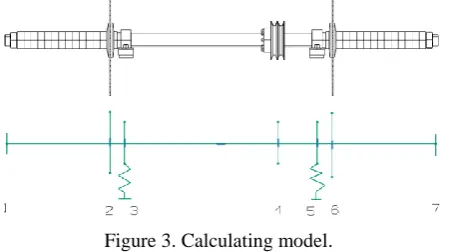
The spindle structure shown in Fig.2 is a typical single-span double cantilever disk "spindle-bearing" dynamic system, which consists of two circular saw blades, two bearings and one belt wheel. After simplifying the structure, the calculation model is obtained as shown in Fig.3.
Figure 3. Calculating model.
The dynamic calculation model is a multi-degree-of-freedom rotor dynamic system considering bearing stiffness, considering the influence of gyroscopic effect, regardless of damp. The dynamic equation of the system is as follows:
Q Kq q J q
M
[image:2.595.188.413.555.681.2]Where M is the mass matrix of the multi-degree-of-freedom system, J is the inertia matrix, Ω is
the angular frequency of the system, K is the stiffness matrix.
q q
q、、 are the displacement, velocity and acceleration vectors of the system respectively, Q is the external force on the system.
For the rotor system, the eigenvalue problems are as follows:
0 ] [ ]
[K 2 M (2) Where is the critical angular frequency and 0 is the zero vector. Because of the existence of gyroscopic moment, the forward critical speed of the system will be increased and the backward critical speed will be reduced.
Finite Element Analysis Model Based on Samcef Rotor
SAMCEF ROTOR is professional rotor dynamics analysis software, which provides a variety of modeling methods. This paper uses 3D model for finite element analysis.
Basic Data
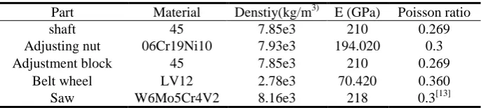
[image:3.595.127.470.349.426.2]The belt wheel is installed in the middle of the spindle and the saw blade is installed in the inmost position. The material properties of the parts are shown in Table 1.
Table 1. Material Properties.
Part Material Denstiy(kg/m3) E (GPa) Poisson ratio
shaft 45 7.85e3 210 0.269
Adjusting nut 06Cr19Ni10 7.93e3 194.020 0.3 Adjustment block 45 7.85e3 210 0.269
Belt wheel LV12 2.78e3 70.420 0.360 Saw W6Mo5Cr4V2 8.16e3 218 0.3[13]
The bearing has a significant influence on the dynamic performance of the spindle. Considering the effect of bearing support stiffness, the overall stiffness of the "spindle-bearing" system will decrease and the critical speed of the whole system will decrease. In this paper, bearing stiffness coefficient and damping coefficient are taken as 2x2 matrices, as shown in Eq.3.
yy yx xy xx k k k kK ,
yy yx xy xx c c c c
C (3)
Where kxx, kyy are the main stiffness coefficients of bearings, cxx, cyy are the main damping coefficients of bearings, kxy, kyx are the cross stiffness coefficients of bearings, and cxy, cyx are the cross damping coefficients of bearings. They are shown in Table 2.
Table 2. Dynamic coefficients of bearings.
Parameters kxx kyy cxx cxy cyx cyy Value 100 100 246.1e1 -194e1 -197e1 561.6e1
Modeling
Critical Speed and Modal Shape
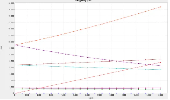
[image:4.595.174.446.138.298.2]According to the data in Table 1 and Table 2, the mass property of each part and the dynamic coefficients of bearings are defined. The rotational speed range is 0-12,000 rpm. The first 10 eigenvalues are extracted and Campbell diagram is obtained as shown in Fig. 5.
Figure 5. Campbell diagram of the first 10 orders.
From Fig.5, it can be seen that there are six orders of critical speed, including three orders of forward motion and three orders of backward motion. The critical speeds of each order are shown in Table 3. The modal shape of each order is shown in Fig. 6.
Table 3. Critical speed.
Foreward rpm Backward rpm
1st order 1751.8 1st order 1699.4 2nd order 2079.59 2nd order 2079.55 3rd order 11125.5 3rd order 9504.1
(a) 1st backward modal shape (b) 1st foreward modal shape (c) 2nd backward modal shape
[image:4.595.113.482.382.547.2](d) 2nd foreward modal shape (e) 3rd backward modal shape (f) 3rd foreward modal shape
Figure 6. Modal shape.
The investigation of the critical speed is mainly the critical speed of forward precession. The working speed of the cutting machine is 5000 rpm, which better avoids the first and second-order critical speeds and is in a stable working area.
Analysis of Factors Effecting Critical Speed
After the design of the cutting machine spindle is fixed, the bearing span does not change. Therefore, this paper mainly examines the effects of bearing stiffness, the installation position of the pulley and the installation position of the saw blade on the critical speed.
Effect of Bearing Stiffness
Table 4. Effect of bearing stiffness on critical speed.
Bearing stiffness (N/mm)
100 200 300 400 500 600 700 800
1st order 1751.8 2470 2606 3474 3874 4232 4559 4679 2nd order 2079.59 2934 3397 4129 4605 5031 5419 5629 3rd order 11125.5 11137 11144 11163 11177 11191 11206 11215
[image:5.595.175.425.219.409.2]The curve of critical speed versus bearing stiffness is shown in Fig. 7, and it can be seen that the first and second order critical speeds increase with the increase of stiffness, while the third order critical speeds do not change significantly with stiffness.
Figure 7. Critical speed varies with bearing stiffness.
Effect of Installation Position of Belt Wheel
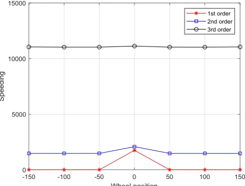
The belt wheel is installed at the midpoint of the spindle in Fig.4, which has no gyroscopic effect on the spindle. However, the gyroscopic effect will occur when the belt wheel deviates from the midpoint position. In this paper, lighter aluminium alloy is selected as the material of the belt wheel. The installation position of the belt wheel is shifted 50, 100 and 150 mm to the left and right respectively. The effect on the critical speed is shown in Table 5. The trend of critical speed changing with belt wheel position is shown in Fig. 8.
[image:5.595.168.413.559.745.2]Table 5. The effect of belt wheel position on critical speed.
Distance Left deviation Middle Right deviation
150 100 50 0 50 100 150
1st order 0 0 0 1751.9 0 0 0
2nd order 1472 1472.4 1472.4 2079.6 1472.2 1472.3 1472.7 3rd order 11049 11030 11030 11125 11030 11029.6 11049.5
As can be seen from Table 5 and Fig.8, the first critical speed becomes rigid mode with 0 speed after the belt wheel position is offset, and the second and third critical speeds decrease slightly relative to the midpoint position, and their values change little with the increase of the offset. At the same time, it can be noted that relative to the midpoint position, the first three critical speeds of the belt wheel are basically symmetrical distribution with respect to the left and right deviations.
Effect of Saw Blade Position
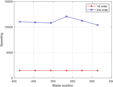
[image:6.595.128.468.88.149.2]According to the different cutting width, the cutting machine adjusts the center distance of two saw blades to adapt to different cutting width. In this paper, the finite element model is used to investigate the change of the first and second critical speeds when the center distance of the saw blade is from 414 to 614 mm, and the third critical speeds are beyond the scope of investigation. The results as shown in Table 6 and Fig.9.
Figure 9. The change trend of the first 2 order critical speed with the position of the saw blade.
Table 6. Effect of saw blade position on critical speed.
Distance
(mm) 414 454 494 534 574 614
1st order 1472.1 1471.1 1469.8 1468.3 1466.4 1464.1 2nd order 11023.7 10908.9 10792.6 12059.7 11236.0 10385.5
Unlike the unilateral adjustment of 4.2 pulley installation position, the change of saw blade installation position belongs to simultaneous bilateral offset. It can be seen from the graph that within the range of variation, the first critical speed of the rotor basically remains unchanged, and the second critical speed fluctuates slightly.
Compared with the one-sided adjustment of the belt wheel position in Section 4.2, the change of the saw blade position belongs to the simultaneous shift of both sides. It can be seen from the Fig.9 that within the range of change, the first critical speed basically remains unchanged, and the second critical speed fluctuates slightly.
Conclusion
[image:6.595.183.409.329.504.2](1) The influence of bearing stiffness has an obvious effect on the first and second order critical speeds, but has a little effect on the third order critical speeds.
(2) The magnitude of the offset of the installation position of the Aluminum belt wheel has no obvious effect on the critical speed.
(3) The position of saw blade has no obvious influence on the first critical speed, but has certain fluctuation on the second critical speed.
In summary, the spindle of double saw blade cutter is sensitive to the dynamic characteristics of bearings. Therefore, the health status of bearings should be paid attention to when checking and maintaining the equipment. According to the analysis of critical speed, the cutting machine has good working stability in the speed range of 2500-8000rpm. The results of this paper can be used as a reference in the design and development of similar equipment.
Acknowledgment
This paper is supported by National Program on Key Basic Research Project (973 Program, Grant NO. 2013CB035706), the Nation Natural Science Foundation of China (Grant Nos. 51705537 and 51175517), the Natural Science Foundation of Hunan Province of China (2018JJ3661)
References
[1] Yi E Zhong, Rotor Dynamics. Beiing: Tsinghua university press,1987.
[2] Zheng Wang, Rotor Dynamics Design of Rotating Machinery. Beiing: Tsinghua university press, 2015.
[3] Deng Wang-Qun, Nie Wei-Jian, He Ping, Guo Tian-Cai, Yang Hai, Variation Laws of Critical Speeds of a High-speed Flexible Rotor with Different Supporting Stiffness, Noise and Vibration Control.2015, 03:98-101.
[4] Luo Zhonghui , Xue Xiaoning , He Zhen, Multi -Critical Speed Accurate Calculation of High-Speed Rotating Shaft, Machine Tool & Hydraulics, 2012, 12:81-82.
[5] Kan Wei-min, Xiao Xiaoqing, Deng Xiaowen, Chen Jianhong, Sheng Deren, Influence Analysis of Bearing Damping Coefficients on Rotor Critical Speeds, Turbine Technology, 2014, 03:213-216+220.
[6] Wu Yuhou, Zhang Jiao, Zhang Li Xu, Shi Huaitao, Analysis of Ceramic Motorized Spindle Rotor Dynamic Characteristics Based on Transfer Matrix and Finite Element Method, Journal of Shenyang Jianzhu Unibersity (Natrural Science), 2014, 03:510-515.
[7] Li Bingcai, Xu Huawei, Wu Xiaowei, Lu Jinjun, Analyzing Dynamic Characteristics of High Speed Motorized Spindle on Transfer Matrix Method. Science Technology and Engineering, 2010, 02:469-471.
[8] Du Chao, Ding Yucheng, Zhao Wanhua, Li Changhe, Analyzing Dynamic Characteristics of Motorized Spindle on Transfer Matrix Method, Manufacturing Technology & Machine Tool, 2010, 10:135-138.
[9] Shen Hao. Analysis of Dynamic Performance of Motorized Spindle Based on Transfer Matrix Method. Machinery, 2010, 48(10):30-31.
[11] Wang Wenhao. The Finite Element Analysis for Cutting Machine Lifting Mechanism Design and Transient Dynamics. Journal of Chongqing University of Science and Technology(Natural Sciences Edition), 2014, 16(4):117-120.
[12] Su Jian. Structure design and finite element analysis of slice component cutting machine. Harbin Institute of Technology, 2007.
[13] Chen Yuacun, Yu Jixing, Ni Xiaochen, Lu Xingxing. Analysis of Fatigue Life of W6M05Cr4V2 High Speed Steel Transmission Shaft . Machinery, 2010, 48(05):53-55.