© 2016, IRJET | Impact Factor value: 4.45 | ISO 9001:2008 Certified Journal
| Page 1195
Multi scale control scheme for designing of Feedback-feedforward
control system
Nese Viswanath
1,R.Kiranmayi
2, K.Nagabhushanam
31Student , Dept.of Electrical &Electronics Engineering, JNTUACEA, Anantapuramu, A.P., India. 2Professor, Dept.of Electrical &Electronics Engineering, JNTUACEA, Anantapuramu, A.P.,India 3Lecturer, Dept.of Electrical &Electronics Engineering, JNTUACEA, Anantapuramu, A.P., India
---***---Abstract - The combination of feedback control and
feedforward control can significantly improve the performance of the system over simple feedback control. Feedforward control provides the corrective action for the disturbance before it can affect the process. Feedback control provides the corrective action for the disturbance even without knowing the disturbance source, but it does not provide predictive control action for known disturbances. The feedback controller was designed by using standard tuning methods for PID controller to provide the better performance of system. The feedforward controller is designed by inversion of the plant model, this may not physically realizable. In this paper, a new systematic method for designing a feedback and feedforward control system individually and for process both control strategies are applied .The proposed method provides good disturbance rejection and improved regulatory control performance.
Keywords: Multi scale control, Regulatory control, Feedback control, Feedforward control
1.INTRODUCTION
A simple way to improve the regulatory control is to combine both feedback and feedforward control system. The feedback controller take correct action for any disturbance, it does not consider the source of disturbance. In the feedback control strategy PID controller is used widely in the process industry due to its robustness and simplicity. This Feedback controller takes action based on the error signal. It improves response of the system. There are different tuning methods are there to get the optimal values for the controller parameters. It does not provide any predictive control action for known measurable disturbance. The feedforward control provides the action for disturbance before it affects to the process. Theoretically the feedforward controller can achieve perfect control performance under perfect process information, but it requires known disturbance measurement. Feedforward controller is effective for known and specified disturbances only. It does
not take any action for unknown disturbances, so it can be used as an additional controller in combination with feedback PID controller. The detailed advantages and information of feedforward controller have been reported in the open literature in [2-4].
Over the years many different approaches have been proposed in order to get better performance. The single loop feedback controller is the common approach of many authors. In that feedback, PID controller is used. In order to get better control performance many uses specific tuning method of PID controller like IMC tuning procedure and LQG procedure. IMC tuning relations are described in [2].
There are two types of feedforward control schemes are classified. Those are ideal and non ideal feedforward controllers. The design of feedforward control is by inverting the plant model this may resulting into physically unrealizable controller, e.g., Due to presence of predictive term lead to non casual transfer function, or degree of denominator is greater than numerator of controller in this case the ideal feedforward controller leads to physically unrealizable. The authors in [4] described designing of feedforward control parameters directly from the Process model.
In this paper, Designing of feedback and feed forward controller based on MSC scheme is explained. The multi scale control scheme application to stable and unstable plants is explained in [10, 11]. The designing method of different feedforward controllers by using MSC scheme is explained in [1]. For those plants MSC FB-FF structure gives the better performance. The main development of this paper involves design of effective feedback PID control and feedforward control with MSC scheme. It gives smooth response than the normal MSC FB-FF control scheme. It invoves effective designing of both Feedback and feedforward controllers.
© 2016, IRJET | Impact Factor value: 4.45 | ISO 9001:2008 Certified Journal
| Page 1196
and comparison of different control strategy performance and section 6 describes about conclusion and future scope of proposed method.
2. FUNDAMENTALS
The fundamentals of the proposed and designing schemes are discussed briefly. The feedback and feedforward control schemes and multiscale control scheme discussed .
2.1.Multi scale control scheme
The multi scale control scheme is the designing method for faster disturbance rejection. The Multi Scale Control scheme basic principle is to decompose the plant into different speed response factors; each factor has different speed of response. Normally for the given transfer function of plant P(s) decomposed into n+1 different speed response factors or modes as
P(s)=J0(s)+J1(s)+J2(s)+………+Jn(s) (1) Here, Ji, (i=0,1, 2,3,…..n) are the plant modes .In this Jn(s) is the fast response factor compare to all remaining factors. i.e. Jn is faster than Jn-1 and Jn-1 is faster than Jn-2 like that J0 is the slowest response factor among all factors .This is the general case of Multi scale Control scheme for n layers. No need of n layer multi scale control scheme for real applications .Normally usage is two layers or three layer MSC scheme.
2.2. Feedback Multi Scale control scheme
For the given plant transfer function decompose into two different factors which has different speed of response is two layer multi scale control scheme.
P(s)=J0(s)+J1(s) (2) Here, J1(s) factor is faster response factor compare with J0(s) so that fast response factor J1(s) is used as multi scale predictor. It is used in inner layer .J0(s) is used as outermost layer as shown in figure .Multi scale predictor is chosen as faster response factor, That it rejects the disturbance effectively with in a small time .This method give good response for the given process model.
Fig.1. MSC Feedback only controller In the figure M(s) is multi scale predictor M(s) =J1(s)
The inner layer transfer function of the figure shown above is
G1(s) = K1(s) / [1+K1M(s)] (3) In the above structure K1 is chosen as P controller for simple controller tuning purpose and K0 is chosen as P+I
controller .There are many different tuning methods are presented by many authors like Ziegler-Nichols PID tuning method.
The overall multi scale controller is
Gc(s) =K0(s) G1(s) (4) The total transfer function from input R to output Y is Hry(s) =Gc(s) P(s)/ [1+Gc(s) P(s)] (5) The transfer function from disturbance D to output Y is Hdy(s) =Gd(s)/ [1+Gc(s) P(s)] (6)
2.3 PID tuning procedure
In the proposed method two different tuning methods are used for tuning PID parameters
1. AMIGO method 2. IMC tuning method
First step in the tuning procedure is to reduce the structure into standard single feedback loop and apply tuning method for the combined plant transfer function. In the tuning of PID controller parameters MATLAB SISO Tool is used .In the toolbox for tuning of parameters classical designing method of PID controller is used in this method .The tuning is applicable to standard structures only that’s why here reduced structure is required in the design. The process of reduction as follows
Fig.2.(a).Standard MSC structure (b).Reduced MSC structure (c).Standard feedback structure.
Here two tuning methods are used in this method. The IMC tuning relations and AMIGO classical tuning relations are mentioned in [5,7]. Many different tuning rules for PID controller described in [8,9].
2.4. Conventional Feedback Feedforward control structure Figure shows the commonly used feedforward with feedback structure .Here, F is the feedforward controller; Gc is the feedback controller and Gd is the disturbance transfer function.
(a)
(b)
© 2016, IRJET | Impact Factor value: 4.45 | ISO 9001:2008 Certified Journal
| Page 1197
The feedforward controller is designed as the direct inverse of plant model under an assumption that, The feedforward controller can cancels the effect of output disturbance to the system.
Fig.3. Conventional FB+ FF control Mathematically design of feedforward controller as [Gd(s) +F(s) P(s)]D(s) =0
From this the feedforward controller
F(s) = -Gd(s) [P(s)]-1 (7)
Due to inversion of plant model, in some conditions the controller might not be physically realizable. The conditions are
Condition 1: Unstable controller if P is non minimum phase system.
Condition 2: Unstable controller if Gd is unstable.
Condition 3: Non causal controller if Plant has higher order than Gd.
A Static feedforward controller will choose if dynamic feedforward controller is not realizable. That is static feedforward filter is
Fstatic= -Gd (0) [P (0)]-1 (8) Here, Gd(0) and P(0) are the steady state gains of the disturbance and plant transfer functions .The static feed forward controller is effective if disturbance and plant have similar dynamics response of Plant and disturbance is similar. When plant and disturbance are different dynamics then the lead lag feedforward controller is preferable, difficulty here is tuning of lead lag feedforward controller is challenging.
3.DESIGNING OF MULTI SCALE FB-FF CONTROL STRUCTURE
3.1 Designing of MSC FB-FF control scheme
Figure represents the multi scale based feedback-feedforward structure. It’s structure is different with conventional feedback –feedforward control .In the multi scale control scheme the disturbance is directly enters into the inner loop .In multi scale control the inner layer is chosen fast response factor, due to its speed response the effect of disturbance D on Y is rejected very fast based on the response of inner layer mode.
In this scheme the disturbance effect on output is removed by the faster inner loop sub controller K1.In conventional feedback-feedforward control scheme, first the disturbance effect on output is removed by feedforward controller then single loop feedback controller. It takes more time to take action on disturbance effect compare to MSC
feedback-feedforward because of the disturbance is rejected by fast feedback action of inner sub controller.
[image:3.595.332.546.126.236.2]
Fig.4. Multi scale control scheme
Based on the fastness in disturbance rejection MSC feedback-feedforward control scheme gives better plant response. The transfer function from Uff to U is
Hfu(s)=1/[1+K1M(s)] (9) The inner layer transfer function
Hbu(s)=K1/[1+K1M(s)] (10) By ignoring the outer feedback loop the transfer function
from output disturbance D to output Y is
Gdy(s)=F(s)Hfu(s)P(s)+Gd(s) (11) The closed loop disturbance transfer function of MSC
feedback-feedforward scheme is
Hdy(s)=Gdy(s)/[1+Gc(s)P(s)] (12)
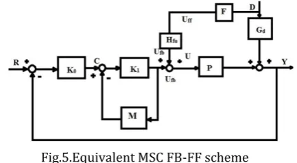
Now reduce the MSC structure into conventional feedback feedforward structure as below
Fig.5.Equivalent MSC FB-FF scheme
Figure shows the reduced MSC scheme as conventional feedback feedforward control scheme. The feedforword controller is
Fmsc(s)=Hfu(s)F(s) (13)
Where, Fmsc(s) is multi scale feedforward controller. For
static feedforward controller
Fmsc(s)=Hfu(s)Fss (14)
If disturbance Gd and plant P have different dynamics
then go for dynamic feedforward filter for effective disturbance rejection .The dynamic feedforward filter is F(s)=Fss/(τff s+1) (15)
Here, Fss is static gain of feedforward controller and τ ff is feedforward filter time constant. If decrease the time
[image:3.595.328.545.445.564.2]© 2016, IRJET | Impact Factor value: 4.45 | ISO 9001:2008 Certified Journal
| Page 1198
adjust dynamics between disturbance transfer function Gd and plant transfer function P(s).
4.DESIGNING PROCEDURE
Designing procedure involves feedback controller and feedforward controller based on multi scale control scheme. Based on the design procedure involves individual designing of controllers for different processes.
4.1 Feedback controller
In the designing of feedback controller involves two steps Step-1: Designing of MSC-PID controller.
Step-2: Designing of MSC feedforward controller with feedback control.
The designing of PID controller is done in this paper is by SISO Tool in MATLAB 2014.In the SISO Tool, IMC tuning and AMIGO tuning method for design of PID controller is used. In MSC scheme, it require two controllers those are inner layer P controller and outermost layer P+I controller.
4.2 Feedforward controller
The main requirement of feedforward controller is to it can cancels out the disturbance effect at steady state. From this static feedforward controller
Fss=-Gd(0)[Hfu(0)P(0)]-1 (16) For minimum Integral Absolute Error to get the optimum values of Fss and τff if static feedforward filter is used.
considered step change as a disturbance.
For obtaining optimum static feedforward filter require to solve
(17)
Result gives optimum value (Fss*) and it gives minimum Integral Absolute Error value for the disturbance rejection.
5.ILLUSTARTIVE EXAMPLES
The concept of proposed method applied for three different types of plants and the results are compared. From the results the proposed method gives the best performance compare to remaining control strategies.
5.1 Example 1: First Order plus Dead Time (FOPDT)
Consider the plant FOPDT with transfer function P(s)= e-5s/(10s+1) (18) Assume output disturbance transfer function Gd(s)= e-5s/(12s+1) (19)
Here The comparison of performance of five different control strategies (i) MSC Feedback only (ii) Dynamic Feedforward control in combination with feedback control (iii) static feedforward control in combination with feedback control (iv) MSC FB-FF control (IMC tuning) (v) MSC FB-FF control (AMIGO tuning) is performed.
From plant and disturbance transfer functions derived the feedforward controller which is physically unrealizable due to presence of predictive term e4s in the numerator, So value of derived static controller
Fss= -1. (20)
If you ignored the e4s term then dynamic feedforward controller is
F(s) = - (10s+1) /(12s+1) (21) In the designing of MSC scheme first step is to decompose the plant transfer function into two basic factors. In the plant considered delay element for that first order Padé formula is used for approximation, The approximated transportation delay and approximated plant transfer function is
P(s) = (-2.5s+1) / [(10s+1)(2.5s+1)] (22) Decompose above plant transfer function lead to P(s)=J0(s)+J1(s) (23) Here J0(s)=1.667/(10s+1)
J1(s)=-0.667/(2.5s+1)
In this project SISO design tool used for the tuning of inner and outer controllers. Initially reduce the structure and used IMC tuning procedure by using SISO design tool in MATLAB 2014a from the tuning, controller parameters as Inner layer controller K1 = 7.57 and K0(s)= -0.114(9.7s+1)/s and giving overall closed loop gain margin about 10 dB for the total feedback system. The overall controller is
By maintaining the inner layer controller constant and tuned the outermost controller by using the AMIGO tuning method in SISO design tool and obtained PI controller parameters as K1 = -7.57 and K0(s)= -0.0816(8.2s+1)/s .In this example Plant and disturbance transfer function have similar dynamics so the optimum static feedforward filter by solving eq (17) then the controller is
Fss* = -5.3
Figure shows that response for different control strategies. The proposed method gives the best regulatory control performance over static and dynamic controllers. The improvement in the results is due to proper designing of feedback and feedforward controller. AMIGO combination gave better performance over remaining.
Fig.6 Nominal response for the system
The proposed MSC FB-FF (AMIGO) scheme gives shorter settling time than other control schemes .Response of MSC
} | )] ( ) ( ) ( [ | { , min = * J
0 1
L R s H sD s dt
© 2016, IRJET | Impact Factor value: 4.45 | ISO 9001:2008 Certified Journal
| Page 1199
FB-FF (IMC) is not smooth that is encountered by outermost controller , by concentrating on that outermost controller the smooth response for proposed method is obtained. The comparison of the time domain specifications mentioned in the below table.
Table.1.Performance of different control strategies of FOPDT process
S. N o
CONTROL
STRATEGY Settling time (msec)
Peak overshoot (%)
1 Feedback only 65 40
2 Dynamic feed forward
controller
65 10
3 Static feed forward
controller
60 15
4 Multi scale
control (IMC) 40 10
5 Multi scale
control AMIGO 33 10
5.2 Example 2: Inverse Response Second Order Plus Dead Time (IRSOPDT) process
The plant transfer function of complex process P(s)= (-5s+1)e-2s / (20s2+4s+1) (24) Assume the output disturbance transfer function G(s)= e-3s/(15s+1) (25) Here comparison of performance of four different control strategies (i) MSC Feedback only (ii) static feedforward control in combination with feedback control (iii) MSC FB-FF control (IMC tuning) (iv) MSC FB-FF control (AMIGO tuning) performed.
From plant and disturbance transfer functions derived the feedforward controller which is physically unrealizable due to non minimum phase system lead to unstable controller, So derived static controller is Fss= -1.
In the designing of MSC scheme first decompose the plant transfer function into two basic factors. In the plant considered delay element for the approximation first order Padé approximated formula used, By approximating transportation delay and the approximated plant transfer function is
P(s) = [(-s+1)(-5s+1)] / [(s+1)(20s2+4s+1)] Decompose above plant transfer function lead to
Here J0(s) =0.294(-31s+1)/(20s2+4s+1) J1(s) = 0.706/(s+1)
In this SISO design tool for the tuning of inner and outer controllers is used. Initially reduce the structure into standard structure and used IMC tuning procedure by using SISO design tool in MATLAB 2014a The obtained the controller parameters of controller K1 = 7.051 and outer layer K0(s)= -0.041(1.7s+1)/s and the overall closed loop gain margin about 5.98 dB for the total feedback system. The overall controller is
By maintain the inner layer controller constant and tuned the outermost controller by using the AMIGO tuning method in SISO design tool and obtained PI controller parameters as K1 = 7.051 and K0(s) = 0.0291(3.1s+1)/s. In this example Plant and disturbance transfer function have similar dynamics so the optimum feedforward filter by solving eq (17)
F*(s)= -5.7/(14s+1) (26)
Figure shows that response of different control strategies. The proposed method gives the best regulatory control performance over static and dynamic controllers. The improvement in the results is due to proper designing of feedback and feedforward controller .The combination of feedback and feedforward control with MSC scheme provide the better control performance.
Fig.7.Nominal response of the system
The proposed MSC FB-FF (AMIGO) scheme gives shorter settling time than other control schemes .Response of MSC FB-FF (IMC) is not smooth that is encountered by outermost controller , by concentrating on that outermost controller obtained the smooth response for proposed method. The comparison of the time domain specifications mentioned in the below table.
© 2016, IRJET | Impact Factor value: 4.45 | ISO 9001:2008 Certified Journal
| Page 1200
S.No CONTROL
STRATEGY Settling time (ms)
Peak overshoot (%)
1 Feedback only 100 50
2 Static feed
forward controller
95 60
3 Multi scale
control (IMC) 85 20
4 Multi scale
control(AMIGO) 80 20
C. Example 3: Integrating First Order plus Dead Time (IFOPDT) process
Consider the process transfer function
P(s)= 0.01e-10s/s (27) Assume the output disturbance transfer function Gd(s)= e-10s/ s (28) Here comparison of performance of three different control strategies (i) MSC Feedback only (ii) MSC FB-FF control (IMC tuning) (iii) MSC FB-FF control (AMIGO tuning)is performed. From plant and disturbance transfer functions derived the feedforward controller which is F(s) = -100s/ (30s+1). (29) The feedforward controller has no steady state gain that means controller cannot compensate disturbance effect at steady state. It is not efficient feedforward controller, so required construction of improved feedforward controller by using the proposed MSC FB-FF control scheme. In the designing of MSC scheme first decompose the plant transfer function into two basic factors. In the plant considered delay element for that first order Padé formula is used, By approximated transportation delay and the approximated plant transfer function is
P(s) = 0.01(-5s+1) / [(5s+1)(s)] (30) Decompose above plant transfer function lead to
Here J0(s) = 0.01/s
J1(s) = - 0.1/(5s+1)
In this SISO design tool for the tuning of inner loop controllers is used. Initially reduce the structure and used IMC tuning procedure for internal controller and LQG procedure for outer controller by using SISO design tool in MATLAB 2014.Obtained parameters of P and PI controller from tuning is
K1 = -80.5 And outer layer controller
K0(s)= -0.0551(20s+1)/s
The overall closed loop gain margin about 5.84 dB for the total feedback system. The overall controller is
By maintaining the inner layer controller constant and tuned the outermost controller by using the CHR tuning method in SISO design tool and obtained PI controller parameters as K1 = -80.5 and K0(s) = - 0.05469(22s+1)/s .In this example Plant and disturbance transfer function have different dynamics so the optimum feedforward filter by solving optimum problem is
F*(s)= -20/(1.7s+1) (31)
Below figure shows that response of different control strategies. The proposed method gives the best regulatory control performance. The improvement in the results is due to proper designing of feedback and feedforward controller .The combination of feedback and feedforward control with MSC scheme provide the better control performance.
Fig.8.Nominal response of the system
The proposed MSC FB-FF (CHR) scheme gives shorter settling time than other control schemes .Response of MSC FB-FF (IMC) is not smooth that is encountered by outermost controller , by concentrating on that outermost controller got the smooth response for proposed method. The comparison of the time domain specifications mentioned in the below table
Table.3.Performance of different control strategies of IFOPDT process
S.no Control
strategy Settling time (ms)
Peak overshoot (%)
1 Feedback only 210 30
2 Multi scale
control (IMC) 210 11 3 Multi scale
© 2016, IRJET | Impact Factor value: 4.45 | ISO 9001:2008 Certified Journal
| Page 1201
6.CONCLUSION AND FUTURE SCOPE
In this paper, a brief designing of feedback and feedforward controller based on multi scale control is explained .In this separate tuning methods of PID controller is used. The proposed method gives the best results. Future study will involve multi loop MSC scheme design or cascade control design and may lead to higher order plants or MIMO system.
REFERENCES
[1] Jobrun Nandong,“A Unified Design for Feedback-Feed forward Control System to Improve Regulatory Control Performance” International Journal of Control, Automation, and Systems ,vol.13,no.01,pp.91-98,march 2015.
[2] D. E. Seborg, T. F. Edgar, and D. A. Melli champ,Process Dynamics and Control, John Wiley &Sons, NJ, 2004. [3] T.E.Marlin ,Process control :Designing Processes and
Control system for Dynamic Performance ,McGraw-Hill,Singapore,2000.
[4] J. L. Guzman and T. Hägglund, “Simple tuning rules for feedforward compensators,” J. Process Control, vol. 21, no. 1, pp. 92-102, January 2011.
[5] Morari, M., and F. Zafiriou. 1989. Robust Process Control. Chapter, Prentice-Hall, NJ.
[6] Rivera, D. E., S. Skogestad, and M. Morari. 1986. “Internal Model Control 4. PID Controller Design,”I&EC Chem. Proc. Des. & Dev. 25, 252–265.
[7] Smith, C. A., and A. B. Corripio. 1985. Principles and Practice of Automatic Process Control. John Wiley & Sons, NY.
[8] Sami Jan Lolu ,Sukhdeep Singh Bhatti ,R.K. Sharma ,”Approaches for tuning of PID controller,” IJERSTE, vol.22,Issue 3,pp. 1-7,March 2013.
[9] Ala Eldin Abdallah Awouda ,Rosbi Bin Mamat ,“ New PID tuning rules Using ITAE Criteria”,IJE vol.3.issue.6,pp 597-608.June 2012.
[10] J. Nandong and Z. Zang, “Novel multiscale control scheme for nonminimum-phase processes,” Ind. Eng. Chem. Res., vol. 52, no. 24, pp. 8248-8249, May 2013. [11] J. Nandong and Z. Zang, “High-performance multiscale