A Secure and Verifiable Visual Cryptography for
Color Images
Ar. Guru Gokul
1,*, N. Kumaratharan
21Department of Computer Science and Engineering, Sri Krishna College of Technology, India 2Department of Information Technology, Sri Venkateswara College of Engineering, India
Copyright © 2015 by authors, all rights reserved. Authors agree that this article remains permanently open access under the terms of the Creative Commons Attribution License 4.0 International License
Abstract
Confidentiality is the most important aspect of information security. Visual Cryptography (VC) is a decryption-less cryptographic technique where human eye is proficient in decrypting the secret information. VC is implemented for binary, gray scale and color images, Color image VC schemes are commonly implemented using Cyan-Magenta-Yellow-Black (CMYK) model that requires a computational device for revealing the secret image but lacks verifiability of the shares. The authenticity of the shares is not assured to the receiver, particularly in color image VC scheme. In case of any alteration, attack or loss in the transmitted data, it cannot be identified by the existing schemes. Unlike the existing models where a device is compulsory for decrypting back color images, the proposed model provides a means to encrypt the color images using Red-Green-Blue (RGB) model where each pixel is processed by its respective RGB components. It enables decryption at the receiver without the assistance of computer or aided devices. In this paper, the above mentioned issues are addressed by the scheme that verifies the integrity of the received shares at the receiver.Keywords
Visual Cryptography, RGB Model, Confidentiality, Shares, Color Codes1. Introduction
Even with the remarkable advancement in computer technology, human visual system is the most convenient and reliable tool for secret recovery. For example, a security guard checks the badge of an employee or a secret agent recovers an urgent secret where no electronic devices are available. To make this possible, Naor and Shamir [2] designed the Visual Cryptography (VC) in which a secret image (printed text, picture, etc.) is encrypted in a secure way such that the secret can be decoded only by the human visual system.
VC is a method of encrypting a secret image into shares
such that stacking a sufficient number of shares reveals the secret image. Each participant holds a share which is usually presented in transparency. Unlike conventional cryptographic methods, VC does not require complicated computations for recovering the secret. Decryption is performed by stacking the required amount of shares one over the other to reveal the secret. A VC Scheme (VCS) is a visual secret sharing scheme in which the secret image is revealed by stacking ‘n’ or more shares.
Yang and Laih [3] have proposed an authentication based cryptography methodology. Authentication plays a major role in both sides of communication. Naor and Pinkas [4] have proposed a VC scheme combined with authentication and identification that is used to transfer data securely to the receiver. Nevertheless, cryptography guarantees security by overcoming attacks by malicious adversaries.
The previous studies by Horng, Chen, and Tsai [5] and Yan, Gan, and Chen [6] show that it is possible to cheat in VC, though it seems hard to imagine. The cheater presents some fake shares, such that the stacking of fake and genuine shares together reveals a fake image. With the property of unconditional security, VC is suitable for sending highly classified orders to a secret agent when computing devices may not be available. The secret agent carries some shares with a pre-determined order while departing and when the head quarter decides to execute a specific order, it simply sends another share to the agent, and the agent recovers the order. It would be terrible if the dispatched share cannot be verified due to a cheater’s attack.
2. Methodologies
The various methodologies used so far in VC are discussed in this section. The basic concepts of RGB model are also discussed.
2.1. General Visual Cryptography
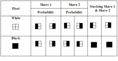
[image:2.595.60.295.346.469.2]In a Visual Secret Sharing Scheme (VSSS) of ‘n’ participants is represented by (n, m), where ‘n’ represents the number of sub pixels forming each pixel and ‘m’ represents the total number of shares generated. Each pixel in a secret image is encoded into ‘n’ black or white (transparent) subpixels in each share of the ‘m’ transparencies. The white subpixels (represented as 0) allow the light to pass through them while black subpixels (represented as 1) stop it. Thus, during decryption, when several transparencies are stacked and held to light, the generalized “or” (denoted as +) result of these transparencies is seen. Fig. 1 illustrates the encoding process of a single pixel, namely ‘p’, in a 2-out-of-2 VC and the result of the generalized “or” operation on the encoded shares.
Figure 1. (2, 2) Visual cryptography scheme
If ‘p’ is black, the encoder chooses the share values form the third row randomly for encoding, namely s1 and s2. If ‘p’ is white, then the encoder chooses the shares from the second row and encodes them as s1 and s2. Similarly, all the pixels in the image will be encoded and each of the possibilities is equally likely to occur. After encoding, neither s1 nor s2 reveals any secret about the original image. When the two shares are stacked together, if ‘p’ is black, then two black pixels will appear else one white and one black pixel will appear.
Depending on the contrast between the reconstructed black and white pixels, our visual system can tell the difference between a black pixel and a white pixel in the reconstructed image.
The encoding principle in Fig. 1 can be represented by two 2 × 2 0/1 matrices:
S0 = �0 1
0 1� (1)
S1 = �1 0
0 1� (2)
where 0 (1) denotes a white (black) subpixel. The white
(black) pixel in a secret image, is encoded as two subpixels for each of the two shares: s1 and s2; further, for the two subpixels on s1 (s2), two values at the first (second) row of S0 (S1) are assigned respectively. Undoubtedly, these two matrices are so critical to achieve secret sharing, hence called as the basis matrices of a 2-out-of-2 VCS.
C0 = ��0 10 1� , �1 01 0�� (3) C1 = ��1 00 1� , �0 11 0�� (4) Let C0 (C1) be the collection of all matrices obtained by
permuting all columns of S0(S1). It is easy to see that each matrix in C0 (C1) can be chosen as the encoding matrix for a
white (black) pixel. Therefore (C0,C1) is called a VSSS. In
this case, using the above matrices as input values, the shares of the image are generated using the algorithm.
2.2. RGB Color Model
The RGB color model is an additive color model in which Red, Green, and Blue light are added together in various ways to reproduce a broad array of colors. The name of the model comes from the initials of the three additive primary colors, Red, Green, and Blue.
The main purpose of the RGB color model is to sense, represent, and display images in electronic systems, such as televisions and computers, though it is also used in conventional photography. Based in human perception of colors even before the electronic age, the RGB color model already had a solid theory behind it.
Figure 2. RGB Color Model
[image:2.595.312.553.441.687.2]manufacturers or even in the same device over time. Thus, an RGB value does not define the same color across devices without some kind of color management.
Typical RGB input devices are color TV and video cameras, image scanners, and digital cameras. Typical RGB output devices are TV sets of various technologies (CRT, LCD, plasma, etc.), computer and mobile phone displays, video projectors, multicolor LED displays, and large screens such as JumboTron, etc. Color printers, on the other hand, are not RGB devices, but subtractive color devices (typically CMYK color model).
3. Proposed System Model
The proposed system focuses on the integrity of the data that is transmitted to the receiver. The mutual authentication is also handled by the proposed algorithm.
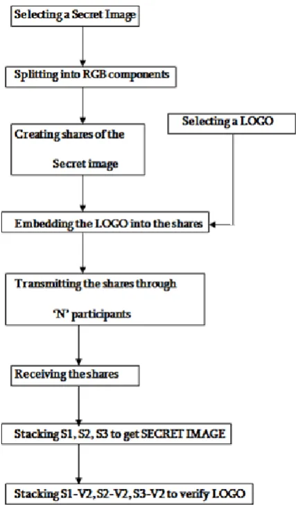
3.1. Verifiable Color Image Visual Cryptography The proposed system is used to authenticate both the message and the sender. Using the proposed model, the integrity of the received message can be verified at the receiver side. It involves the following steps:
1) Select a secret color image and a color logo.
2) Split the secret color image and color logo into RGB color components.
3) Create shares of the secret image.
4) Embed one half of the logo into each of the shares. 5) Transmit of shares through n participants.
6) Receive the shares at the receiver side.
7) Stack the primary shares to reveal the secret image. 8) Stack the verification share to authenticate the shares.
The assumption in the proposed model is that the Color Logo or Verification Logo (V) is known to both the sender and the receiver.
The shares generated can be printed on transparency sheet and are transmitted to the receiver. The shares can also be transmitted via Fax or Electronic mail and can be printed at the receiver.
[image:3.595.325.539.75.440.2]The proposed system model is represented as follows:
Figure 3. Verifiable Visual Cryptography System
Though only the sender is authenticated, it is applicable to both ends since both the sender and receiver agree on a common verification logo. This scheme also conceals the integrity of the message transmitted.
3.2. Verifiable Visual Cryptography Algorithm
The proposed system algorithm takes two color images as input and produces 4 shares as output. First input image is the secret image to be transmitted whereas the second one is the Verification Logo.
Table 1. Nomenclature
Parameter Explanation
R1 Red component of the Input Secret Image
G1 Green Component of the Input Secret Image
B1 Blue Component of the Input Secret Image
R11, R12, R13 Separated Shares of R1
G11, G12, G13 Separated Shares of G1
B11, B12, B13 Separated Shares of B1
Rf Concatenated Share of R11, G11, B11 (Share 147)
Gf Concatenated Share of Each component’s Second Share (Share 258)
Bf Concatenated Share of Each component’s Third Share (Share 369)
Sim Concatenated Image of Rf, Bf and Gf
The proposed system algorithm includes the following steps:
Step 1: Input a RGB image.
Step 2: Separate the color image into its RGB color components namely R1, G1, and B1.
Step 3: Halftone each of the separated components using Jarvis half toning algorithm.
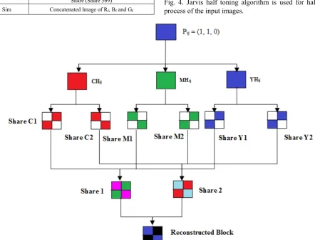
Step 4: Separate half toned component into three shares with no trace of secret image as R11, R12, and R13, G11, G12, and G13 , B11, B12, and B13 and 9 shares are formed using the basic (k, n) VC Scheme.
Step 5: Concatenate first share of each of the color component share as
Rf = R11 + G11 + B11
Step 6: Similarly, concatenate the second and third each color component share.
Gf = R12 + G12 + B12, Bf = R13 + G13 + B13 Step 7: The three shares of the input secret image are transmitted through different participants.
Step 8: At the receiver side, the three shares are stacked to obtain the revealed secret image.
Sim = Rf + Gf + Bf
The pixel processing in the proposed model is shown in Fig. 4. Jarvis half toning algorithm is used for halftoning process of the input images.
[image:4.595.80.523.384.720.2]4. Experiments and Discussions
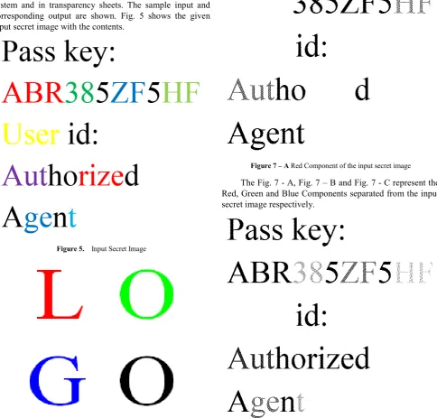
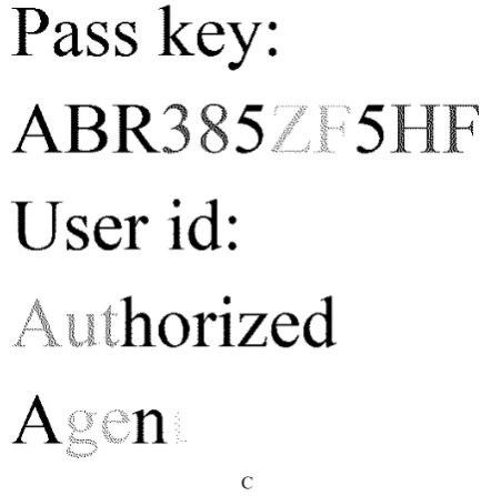
[image:5.595.307.542.73.313.2]The proposed model is evaluated by providing different types of color images (eg. Text, Numbers, Symbols etc.,) as input and the corresponding outputs generated are verified in system and in transparency sheets. The sample input and corresponding output are shown. Fig. 5 shows the given input secret image with the contents.
[image:5.595.65.550.136.599.2]Figure 5. Input Secret Image
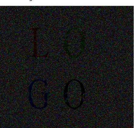
Figure 6. Input Logo
The Verification Logo (V) used to verify each share at the receiver is represented in Fig. 6. This logo is divided into 2 Shares. One share is embedded along with the shares of secret image and the second share is sent directly to the receiver either as a hard copy or through E- mail.
Figure 7 – A Red Component of the input secret image
The Fig. 7 - A, Fig. 7 – B and Fig. 7 - C represent the Red, Green and Blue Components separated from the input secret image respectively.
[image:5.595.242.538.370.607.2]C
Figure 7 – C. Blue Component of the input secret image
• Each separated components of the input secret image is further divided into 3 shares each, and a total of 9 shares are generated.
• The shares of the Red component are named as Share1, Share 2 and Share 3.
• The shares of the Green Component are named as Share 4, Share 5 and Share 6.
• The shares of the Blue Component are named as Share 7, Share 8 and Share 9.
• Once the shares are generated, the first shares of each component is concatenated to form the first secret share 147 as represented in the Fig. 8 – A.
• Similarly the second shares from each component are concatenated to form the second secret share 256 represented in Fig. 8 – B.
• The last shares in each component are combined similarly to form the last secret share 369 represented in Fig. 8 – C.
[image:6.595.66.283.75.299.2]The halftoned verification logo using Jarvis halftoning algorithm is further divided into two shares using the VC algorithm. The first share is embedded with each secret shares and second share is represented in Fig. 8 – D. The images can be of any format, but for more apparent method the images should be in BitMap (bmp) format. There is no restriction on the size of the input image. The algorithm is implemented in a way, such that input image of any size greater than 400 x 400 will be converted into an image of size 400 x 400.
Figure 8 – A. Generated Share 147
Figure 8 – B. Generated Share 258
[image:6.595.325.541.77.289.2]Figure 8 - D. Verification Share
The generated shares are transmitted to the receiver either as a printed copy in Transparency sheets or through E – mail. The main advantage of the proposed system is that there is no need of any cryptographic algorithm or any specialized software at the receiver to decrypt the message. The only computational device required is a printer at the receiver side in some cases, provided the message is transmitted through a wireless medium. Once the shares are received at the other end, to reveal the secret image, the Share 147, Share 258 and Share 369 are stacked together.
[image:7.595.321.545.76.292.2]The proposed system is mainly used to verify the integrity of the transmitted image. To verify the integrity of the message, the verification share is stacked along with each of the secret image shares. Once the verification share is stacked, the verification logo is revealed if there is no alteration in the shares during transmission. If there is any attack or alteration during transmission, the logo will not be revealed.
[image:7.595.320.544.81.507.2]Figure 9 – A. Secret Image Revealing
Figure 9 – B. Authentication of Share 147
Figure 9 – C. Authentication of Share 258
[image:7.595.68.290.523.736.2] [image:7.595.322.543.525.735.2]To further confirm the validity of the proposed scheme different image sets, each of different sizes are given as input and the corresponding outputs generated are verified.
5. Conclusions
VC scheme is commonly used to transmit data to the receiver where no computational devices are required to decrypt the message. The color image VC schemes broadly use CMYK color model to process the data. The CMYK model involves computational algorithms at the receiver and in some cases, the security of the data transferred is also not guaranteed. Though the data is transmitted securely by the existing VC schemes, the integrity of the shares transmitted are not guaranteed.
[image:8.595.62.304.432.543.2]The integrity of the data plays a major role during the data transmission. The existing schemes do not have any claim to prove about the integrity of the received message. The proposed model uses RGB color model which is an additive color model and does not require any devices or algorithms at the receiver to process the message. So, as to ensure that no middle man is involved in this transmission, a verification scheme at the receiver is introduced in the proposed model. The proposed algorithm in MATLAB 7.9 was tested in Lenovo G50 machine by providing images of various dimensions. The images provided for evaluation are in bmp format.
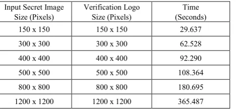
Table 2. Execution Time of Proposed Algorithm Input Secret Image
Size (Pixels) Verification Logo Size (Pixels) (Seconds) Time
150 x 150 150 x 150 29.637
300 x 300 300 x 300 62.528
400 x 400 400 x 400 92.290
500 x 500 500 x 500 108.364
800 x 800 800 x 800 180.695
1200 x 1200 1200 x 1200 365.487
Even though the existing VC schemes transfer the data secretly to the receiver, there are no accurate methods to verify the originality of the data. This shortcoming has been trounced by the proposed scheme. The proposed algorithm
though is more time consuming but the authentication factor is satisfied by the scheme. By using the verification scheme, the integrity of the shares at the receiver is guaranteed. If there is any alteration or attacks in the shares during transmission, they can be easily identified at the receiver. The verification scheme involves individual verification of each share to reveal the secret key that has been encoded along with the secret data. In the future, the contrast of the revealed images can be increased. Another issue that must be addressed is the increased pixel expansion factor.
REFERENCES
[1] Shyu, S. J. (2006). Efficient visual secret sharing scheme for color images. Pattern Recognition, 39(5), 866-880.
[2] Naor, M., & Shamir, A. (1995). Visual cryptography. In Advances in Cryptology—EUROCRYPT'94 (pp. 1-12). Springer Berlin/Heidelberg.
[3] Yang, C. N., & Laih, C. S. (1999) Some New Types of Visual Secret Sharing Schemes. In Proceedings of National Computer Symposium, 3, 260-268.
[4] Naor, M., & Pinkas, B. (1997). Visual authentication and identification. In Advances in Cryptology—CRYPTO'97 (pp. 322-336). Springer Berlin Heidelberg.
[5] Horng, G., Chen, T., & Tsai, D. S. (2006). Cheating in visual cryptography. Designs, Codes and Cryptography, 38(2), 219-236.
[6] Yan, H., Gan, Z., & Chen, K. F. (2004). A cheater detectable visual cryptography scheme. JOURNAL-SHANGHAI JIAOTONG UNIVERSITY-CHINESE EDITION-, 38(1), 0107-110.
[7] Blundo, C., De Santis, A., & Naor, M. (2000). Visual cryptography for grey level images. Information Processing Letters, 75(6), 255-259.
[8] Ateniese, G., Blundo, C., De Santis, A., & Stinson, D. R. (1996). Visual cryptography for general access structures. Information and Computation,129(2), 86-106.