ACTUAL PROTOTYPE ANALYSIS FLOOR PLAN FOR GENERAL
ELECTRIC MACHINE
Gadafi M.Romalan, Erwan Sulaiman, M.Z.Ahmad, Mohd Fairoz Omar and Mahyuzie Jenal
Research Centre for Applied Electromagnetic (EMC), Department of Electrical Power Engineering Universiti Tun Hussein Onn Malaysia, Parit Raja, Johor, Malaysia
E-Mail: [email protected]
ABSTRACT
Each fabrication work from prototype production, small scale production and mass production consists their own process or called floor plan to assist the whole process via forward or backward technic which being consider the best way to produce product. Cause of various process needed for different product especially in initiated general electric machine prototype, there is no complete process being introduced as proper guide from beginning to end lie process. Actual Prototype Analysis (APA) floor plan which covers five stages from completing of the machine design, material selection, machining process, assembling process and testing process is proposed. Generally, the APA covers experimental analysis approach of the five main stage being design as a flow line in the fabrication process and each line consist their own floor plan to be executed before completion of the stage. The whole process requires validation of the results from Finite Element Analysis (FEA) simulation data to actual processing data that can be used as completion of fabrication process for general electric machine (GEM) and as basic to others fabrication.
Keywords: Actual prototype analysis (APA), finite element analysis (FEA), general electric machine (GEM).
INTRODUCTION
The industrial revolution took place long time ago even to create small applications in human society life. With the machine started to prove the ability in making human life better and be one of the item that important in society, more idea take place to make the better machine. Most of idea being realized by try and error method which considered unpractical even it left a big impact for technology development. A few method being introduced as a core before some technology being imparted into society or industry such simulation and fabrication.
Due to most researchers concentrated on design the machine using finite element analysis (FEA) simulation, the approach for the fabrication process indeed lags. So, most designs are evidenced by comparison with the FEA study instead of with experimental results. A complete process or approach to fabricate should be carried out from the initial line to end of line fabrication. All the approach process needs to configure first before the machine can be fabricated so the future works in fabrication more easier and the comparison can be made either the machine is worth or otherwise.
Prototype is an early sample, model, or release of a product built to test a concept or process to act as a thing to be replicated or learned from. Most of item or machine being developed as prototype first before go to small scale production and mass production as first precaution to make further test. By that, the term actual prototype being used to state the prototype was developed and the experiment will carry out based actual simulation.
Based Oxford Dictionary of Philosophy, analysis is defined as the process of breaking a concept down into more simple parts, so that its logical structure is displayed. The restriction to concepts and the reference to displaying ‘logical structure’ are important qualifications, but the
core conception remains that of breaking something down (Beaney, 2015). Quiet recently, the concept of analysis is depend on the structure of study itself and didn’t have specific flow to define for worldwide use.
The approach use actual prototype to analyze will give more satisfaction and as proof to validate the FEA simulation. Data from the analysis will lead to more idea and a solution junction if the result not as expected. From there, the product which will use by society and industry achieve the desired level state by government or appropriate body.
ACTUAL PROTOTYPE ANALYSIS (APA)
Introduction of Actual Prototype Analysis (APA) Actual prototype analysis (APA) is an approach for general electric machine fabrication (GEM) and can be used as a base for others fabrication process as well. Element in APA used a flowchart in Figure 1 as a floor plan for each stage to guide the whole fabrication process of simulation design from the initial line to end line fabrication process.
The approach being broke into five main process as base to validate FEA simulation which consists five main stages from complete design, select material, machining process, assemble process and testing process. Each stage will be guided by their own flow chart to determine the process to act, data and decision which depend on objective for each APA structure.
will be used to measure the performances GEM (E. Sulaiman, 2012) and to create a new FEA data based APA.
With this, complete fabrication of design is able to finish on time guided by flowchart of FEA and APA to analyze and compare the result. At the end of the fabrication, the data is able to conclude the APA approached and capable to fulfil all requirements in flow design as one of suitable complete process to fabricate GEM and impart the technology to society or industry.
Figure-1. APA flowchart.
First Stage: Complete Design
The simulation FEA study uses JMAG Designer software to complete the sketch up to set the rotor, stator, permanent magnet and region for windings while SOLIDWORKS 2014 software been used to design others parts to make design and assembly design (Yang Song, 2010). Completed design is needed to show whole set prototypes, especially for complex structure such as shaft,
The completed design should able to show if unmatched parts before the material being selected and the machining process begins. This process made the assembly process more clearly in how the prototype will end and the unmatched parts can easily changed to match part just by editing that part only. The 3D view of each part and assembly process will provide the real assembly process more smooth. SOLIDWORKS software itself is able to generate the FEA study such as strength analysis assuming the material is similar as the fabrication material. Figure-2 shows the flow chart in completing design process.
Figure-2. Complete design flowchart.
through SOLIDCAM software part by part. It saves time from making the "G" code based sketch.
As illustrated in Figure-2, the design flowchart is divided into three phases of creating part, assembling 3D component and finishing. The step is for GEM fabrication process from the first phase to create a part from simulation FEA of JMAG Designer and support part to realize the application machine. The part being saved in ‘. SLDPRT’ which state as part in drawings section. Second phase following by 3D assembly to determine the phase 1 is completed sketch based right dimension and ready to mate in assembly without mate disposition mean failure to combine the ‘.SLDPRT’. The second process being saved as ‘.SLDASM’ which state as assemble in the drawings section. The last phase is finished, the process is to confirm that first and second phase is capable to fabricate by manufacture in term of machine tools and machining ability.
Second Stage: Select Material
The material is a broad term for the chemical substance or mixture, substance that consist things such as raw material, biomaterial and composite material. In GEM, the material is factor item in determining success or fails the fabrication process through a selected material table for certain application. Different material is selected for different part, same as to GEM design.
The material applied in the FEA study for rotor, stator, permanent magnet and windings will be used to create the prototype unit in affording to achieve the same result in APA study. However, the other part such as holder, retaining clip, shaft and housing will be decided through discussion with manufacture to find the best solution to fabricate the design using standard market material in motor fabrication.
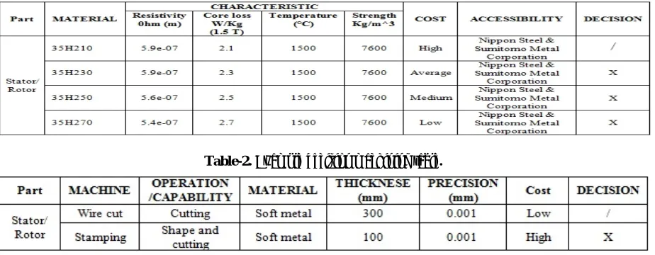
Table-1 show example of selected material use in GEM fabrication which being decided as the best material for the moment, based on three factor of characteristic, cost and accessibility. The table will be guidance to find the most suitable material for prototype fabrication and
mass production. As example in the table, for stator and rotor parts, the 35H210 material types was chosen because low core loss in 2 watts per kilogram at 1.5 tesla due to magnetic flux.
Third Stage: Machining
The machining is part of the manufacturing process which uses pieces of raw material cut into desired shape by controlling material removed process. The common controlled removed process are collectively known as subtracting manufacturing, which implies the use of machining tools with addiction power tools and hand tools (Groover, Mikell P.,2007).
To generate a certain part of geometry, a few machining operations can be used such as turning, drilling, cutting and milling. Precision and capability are the key and objective of stage three which consider a machine that will be used in fabrication process specifically for GEM. A few criteria shall be carried out as a reference to choose more specific machine such as listed in Table 2.
In the machining stage for GEM, precision work is noteworthy because tolerance in all mate parts is quite important in making the machine robust for fabricating. The precision and tolerance of stator, rotor and supporting parts are set up to 0.01 millimeter and 0.03 millimeter, respectively. From there, the set precision, material and design are collaborate together to match with the machine capable in term of tools support, direction and fabrication cost of the prototype GEM.
In prototype point of view, the cost is always high due to limitation of machining. As example, the stator and rotor part is fabricated using wire cutting machine because the new design require new mold to using stamping machine. In contrast with small scale and mass production, where the fabrication machine is unlimited due to production in huge quantity and the mold will be a great choice even starting cost is higher. The mold will be used in stamping process for stator and rotor and replicate it in mass quantity by short time.
[image:3.612.78.540.563.743.2]Table-1. Example decision material table.
Fourth Stage: Assembly Process
To realize decision stage 1 to 3, the part being processed after machining will be assembled as 3D assemble in SOLIDWORKS 2014. The measurement tools will be used as the first phase of assembling process which executes the process in determining whether the part being create as set-out in 2D sketch. This process also to make sure the tolerance in the drawing is compatible for combination whole party together.
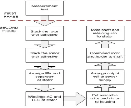
[image:4.612.77.292.294.471.2]The second phase followed by eight steps in assembling process is illustrated in Figure-3. The step specializes for GEM assembling which consider internal part to external part. This process will make sure the actual assembling proceeds as assembly process in 3D sketch design and to avoid the mismatch condition that will lead to failure of the fabrication process.
Figure-3. Assembling process for GEM prototype.
The eight steps consisted of collaboration of hand tools and machine tools to fulfill the perfect assembling process. Especially for winding process which will affect most outcomes of GEM. Figure-4 shows example GEM of 3D outer-rotor assembles in SOLIDWORKS 2014 (E.Sulaiman, 2013) FSM. The position of each part shows the internal and external GEM from excited part to housing as holder for whole combination.
Fifth Stage: Test Process
The testing process is climaxing for APA flow to validate the simulation FEA study. Test management flowchart as Figure 5 will be used as base to complete the APA process which consist planning, control and finishing. The management for planning being determined as a test in simulation FEA by varying certain part.
Control management will be commanded by motor torque measurement machine in Figure-6 that
(a) and (b) to compare with simulation FEA by JMAG Designer.
As illustrated in Figure-6, the block diagram of measurement system is consisted with 5 combination factors where red block is the prototype machine, brown block is the control, blue block is the modifier item, yellow block is the sensor and green block is the monitor. The control unit or commonly known as motor driver will act as the main system and will handled the version of the system. The controller known as modifier which being modified in many combinations to satisfy the end line of GEM performance. The performance will be carried out by yellow block which consist of sensor such as torque sensor, speed sensor and position sensor and deliver the outcome to view by last factor, monitor section.
The whole factor in control management will affect the outcome of finishing management as well as the failure fabrication process if the assembling factor is not in sequence attachment. Arrow line in block diagram describes the sequence and position of each factor to be to realize the last stage in APA. Outcome of finishing management will validate the simulation FEA by JMAG Designer is true or otherwise.
CONCLUSIONS
[image:4.612.319.550.535.698.2]Figure-5. Test management flowchart.
Figure-6. Block diagram torque measurement system.
(a)
(b)
Figure-7. (a) Example torque speed characteristic graph, (b) Example comparison FEA of 12S-14P OR-HEFSM
and IPMSM.
ACKNOWLEDGEMENTS
This work funded by Research Innovation, Commercialization and Consultancy management (ORICC) with Vot No E15501, FRGS 1508 & ERGS 030, Universiti Tun Hussein Onn Malaysia (UTHM) and Ministry of Education Malaysia (MOE).
REFERENCES
[1] E. Sulaiman. 2012. “Less Rare-Earth and High Power Density Flux Switching Motor for HEV Drives,ǁ International Conference on Electrical machine ICEM pp. 15-23, June.
[2] Beaney Michael. 2015. "Analysis", The Stanford Encyclopedia of Philosophy (Spring 2015 Edition), Edward N. Zalta.
[3] Yan Song, Jian-xun Zhang, Xiao-hong Jiang, Li He and Kai Lv. 2010. "Special software's development of spiral chute for design and expression based on the redevelopment of solidworks," Advanced Computer Theory and Engineering (ICACTE), 3rd International Conference on , vol.1, no., pp.V1-343,V1-347, 20-22 Aug. doi: 10.1109/ICACTE.2010.5579004
[4] Groover and Mikell P. 2007, "Theory of Metal Machining", Fundamentals of Modern Manufacturing (3rd ed.), John Wiley & Sons, Inc., pp. 491–504, ISBN 0-471-74485-9