DEVELOPMENTS IN S7iNDWICH CONSTRUCTION
A Thesis submitted for the Degree of
DOCTOR OF PHILOSOPHY
by
SlAViSH TAJBAXHSH
Department of Civil Engineering University of Salford
2.1.3 Analysis of Sandwich Beam with Thick
Facings-Staxnm' and Witte's Theory. 43
2.1.3.1 General Principles. 44
2.1.3.2 Simply Supported Beam with
Point Load P. 49
2.1.3.3 Simply Supported Beam with
Four Point load. 52
2.2 calculating the Shear Modulus of the
Developed Honeycomb Core. 54
2 • 2 • 1 Introduction 54
2.2.2 Calculation of Shear Modulus. 55 CHAPTER 3: TESTS TO DETERMINE MATERIAL
PROPERTIES.
3.1 Introduction. 62
3.2 Notation. 64
3.3 Core Properties.
3.3.1 Shear Test. 69
3.3.1.1 lap Shear Test According to BSI
4370, DIN 5342 and ISO 1922. 69 3.3.1.2 Lap Shear Test According to ASTM
C273-61. 71
3.3.2 Review of Other Work on the Shear
Properties of Foamed Core. 72
3.3.2.1 Four-Point Test. 73
3.3.2.2 Dynamic Test on Simply
Supported Beam. 75
3.3.2.3 Test with a Joined Square. 76
3.3.2.4 Double Block Test. 78
3.4 Standard Compression Test. 78
3.4.2 Compression Test According to ISO 844,
DIN 53421 and BSI 4370. 79
3.5 Standard Tensile Test. 80
3.5.1 Tensile Test According to ISO 1926 and
DIN 5430. 80
3.5.2 Tensile Test According to BSI 4370. 82 3.5.3 Tensile Test According To ASTM C297. 84 3.6 Discussion on Described test Methods. 85 3.6.1 Discussion on Shear Test Methods. 85 3.6.2 Discussion on Compression Test Methods. 86 3.6.3 Discussion on Tensile Test Methods. 87 3.7 Authors Experiments to Determine Core
properties. 88
3.7.1 Joined Square Shear Test. 89
3.7.2 Compression Test. 90
CHAPTER 4: TIMBER-BASED FACING MATERIALS.
4.1 Introduction. 92
4.2 Plywood. 94
4.2.1 Theories of Plywood Bending. 95
4.2.2 Elastic strain Theory. 96
4.2.3 Geometrical Properties of Plywood. 98
4.2.3.1 Moment of Inertia. 98
4.2.3.2 Section Modulus. 99
4.2.4 Methods of Test for Clear Plywood. 100 4.2.5 Recommendation for the Use of Plywood. 101
4.2.6 Canadian COFI Plywood. 102
4.2.6.2 Properties of COFI Exterior
Plywood. 103
4.2.7 American Plywood. 112
4.2.7.1. Veneer Classification. 112 4.2.7.2 Exposure Durability
Classification. 113
4 • 3 Particleboard. 118
4.3.1 FINSA (Forest Product Ltd.) 120
4.3.2 Caberboard. 121
4 • 3 • 3 Torvale-Sasmox. 122
4.3.4 Oriented Strand Board. 123
4.3.5 Sterling Board. 124
4.3.5 • 1 Sterlingboard Applications. 124 4.4 Comparison of Described Plywoods and
Part icleboards. 126
4.4.1 General 126
4.4.2 Comparison of American Plywood With
COFI Plywood. 127
4.4.3 Comparison of Plywoods and Particleboards. 128 4.5 Suitability for Sandwich Panel
Construction. 131
4.6 Conclusion. 132
CHAPTER 5: PLEXURAL TESTING OF SANDWICH BEAMS WITH TIMBER BASED FACING AND PLASTIC RIGID FOAMED CORE.
5.1 Introduction. 135
5.2 Manufacturing of the Beams. 138
5.3 Small Scale tests. 138
5.4 Flexural tests. 143
5.5 Test Results. 146
5.6 Analysis and Discussion. 149
5.7 Conclusion. 150
CHAPTER 6: DEVELOPMENT OF STRUCTURAL FIRE RESISTANT SANDWICH CORE.
6.1 Introduction. 158
6.2 Honeycomb Sandwich Core Material. 162
6.3 Paper Honeycomb Core. 167
6.4 Impregnation of Paper Honeycomb Core with
Sodium Silicate solution. 168
6.4.1 Modification of Sodium Silicate. 169 6.4.1.1 Admixture of Sodium Silicate and
Latex. 171
6.4.1.2 Glass Fibre Reinforcement. 171 6.4 • 1.3 Inorganic Filler-reinforcement. 173 6.4.1.4 Admixuter Sodium Silicate and
vermiculite. 173
CHAPTER 7: COMPARATIVE TENSILE TEST ON STRIPS OF TREATED PAPER.
7.1 Introduction. 177
7.2 Paper As a Material. 178
7.3 Determination of Paper Thickness. 181
7.4 Preparation of Test Pieces. 182
7.5 Tensile Test Procedure. 184
7.6 Analysis of the Results. 185
7.8 Discussion and Conclusion. 195 CHAPTER 8: EXPERIMENTAL WORK ON SANDWICH BEAM
WITH NEWLY DEVELOPED HONEYCOMB CORE.
8.1 Introduction. 202
8.2 Authors Experiments to Determine
Developed Honeycomb Core Properties. 208
8.2.1 Shear Test. 208
8.2.2 Compression Test. 208
8.3 Test Results. 209
8.4 Discussion of the Test Results. 213 8.5 Shear Modulus of the Cell wall Material. 216
8.6 Conclusions. 220
CHAPTER 9: DEVELOPMENT OF A FIRE RESISTANT HONEYCOMB CORE.
9.1 Introduction. 221
9.2 Potential Fire Hazards. 222
9.3 Performance Criteria. 223
9.4 Fire Testing Facilities. 225
9.4.1 Furnace. 225
9.4.2 Furnace Temperature. 225
9.4.2.1 Time Temperature Control. 228
9.5 Test Arrangement. 230
9.6 Commercial Panel Test. 232
9.7 Test Specimens Construction. 233
9.8 Fire Test Results. 238
9.9 Comparison of the Results. 269
9.3.0 Conclusion. 273
9.13. Suggestion for Further research. 275
CHAPTER 10: GENERAL DISCUSSION AND CONCLUS ION
10.1 Discussion. 277
10.1.1 General. 277
10.1.2 Material Property Tests. 278 10.1.3 Timber-Based Facing Material. 279
10.1.4 Sandwich Beam. 279
10.1.5 Core Development. 281
10.1.5.1 Structural Development. 281
10.1.5.2 Fire Performance. 285
10.2 Conclusions. 288
APPENDIX A Computer Programme and Typical
Output. 292
APPENDIX B: Detailed Test Results for Determination of Materials
properties. 298
APPENDIX C: Tensile Test Results on Treated
Paper Strips. 300
APPENDIX D: Typical Calculation of Honeycomb
Core Shear Modulus. 309
Table 3.1 4.1 4.2 4.3 4.4 4.5 4.6 4.7 4.8 4.9 4 • 10 4.11
4.12
4 . 13 4.14 4.15 4.16
LIST OF TABLES
Chapter 3 page No.
Typical material properties of rigid
plastic foams used in sandwich panels 68 Chap ter 4
Regular grades of COFI Exterior plywood 104 Selected British Colombia species used
in COFI Exterior plywood 105
Section properties for standard const-ruction of regular grades of unsanded
COFI Exterior 106
Section properties of regular grades of
sanded COFI Exterior Douglas Fir plywood 107 Dry grade stress and moduli for unsanded
COFI exterior Canadian softwood plywood 108 Dry grade stress and inoduli for sanded
COFI exterior Douglas Fir plywood 109 Dry grade stress and inoduli for sanded
Exterior Douglas Fir plywood 110
Modification factor 111
Modification factor for duration of load 111 Allowable stress for APA structural I 115 Allowable stress for APA rated sheathing
Exp 1 or 2 116
Allowable stress for APA rated sheathing
EXT 117
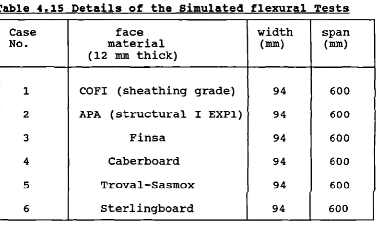
Stress and moduli for particleboards 129 Result of study by Lee and Stephens 130 Details of simulated flexural tests 133 Summary of the results for beams with
4 . 17 4.18 5.]-5.2 5.3 7.1 7.2 7.3 7.4 7.5 7.6 7.7 7.8 8.1A 8. lB 8 . 2A
8. 2B
8.3A
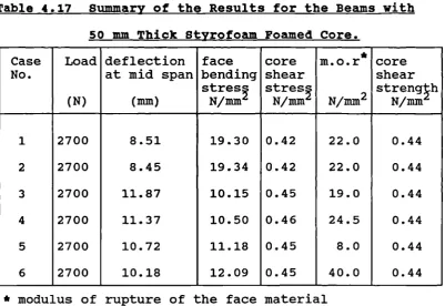
Summary of the results for beams with Styrofoam core
Calculated stiffness of the beams Chap ter 5
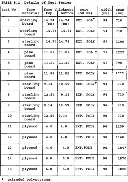
Details of tests series
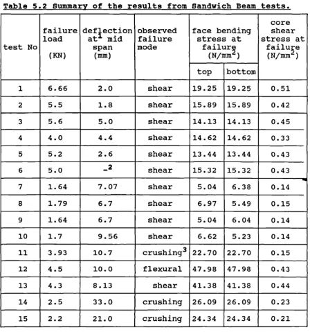
Summary of the sandwich beam tests
The calculated stress at failure and strength of materials
Chap ter 7
Result of the tensile tests on untreated British Telecome directory page
Result of the tensile tests on untreated Chipboard paper
Result of the tensile tests on untreated Kraft paper
Effect of paper quality on paper stiffened with Sodium silicate
Effect of paper quality on paper stiffened with Sodium silicate and ball clay
Strength potential of various coatings Effect of each type of coating on elastic modulus
Stiffness to weight ratio of each type of coating
Chapter 8
Details of test series Details of test series
Cell geometry of the honeycomb cores listed in table 8.1A
Cell geometry of the honeycomb cores listed in table 8.lB
Summary of the results
8.3B Summary of the results 211 Chapter 9
9.1 Test results of the commercial panels 239 9.2A Test series for cores treated with
sodium silicate (unfilled) 240
9.2B Fire test results for cores treated
with sodium silicate (unfilled) 240 9.3A Test series for cores treated with
sodium silicate (filled) 241
9.3B Fire test results for cores treated
with sodium silicate (filled) 241 9.4A Test series for cores treated with
sodium silicate and ball clay (unfilled) 242 9.4B Fire test results for cores treated with
sodium silicate and ball clay (unfilled) 242 9.5A Test series for cores treated with
sodium silicate and ball clay (filled) 243 9.5B Fire test results for cores treated with
sodium silicate and ball clay (filled) 243
9.6A Detail of test panel P 244
9.6B Fire test result of panel P 244
9.7A Detail of test panel S 245
9.7B Fire test result of panel S 245
9.8 Comparison of fire test results for
panels A and B 269
9.9 Comparison of test results for panel A,
B,C and D 269
9.10 Comparison of test results for panel X,
T andy 270
9.11 Comparison of test results for panels A
andl 271
9.12 Comparison of test results for panels X
9.13 Comparison of test results for panels R
and J 272
9.14 Comparison of test results for panels G
and S 272
App endix B
bi Shear test results on plastic rigid
foamed core 298
b2 Compression test results on EXT.
polystyrene 298
b3 Flexural test on timber-based facings 299 App endix C
Cl-C9 Tensile test results on treated paper
Figure 1.1 1.2
2 . 1-2 . 2
2.3 2.4 2.5 2.6 2.7 2.8 2.9 3.1 3.2 3.3 3.4 3.5 3.6 3.7
LIST OF FIGURES
Chapter 2. Sandwich Panel
Hexagonal honeycomb Chapter 2
Sandwich panel with various types of facings
Sandwich beam cross section
Shear stress distribution in sandwich beams
Shear deformation of sandwich beams Forces and deformations in a typical sandwich element
Simply supported beam under point load Diagrammatic presentation of 4-point loading
The geometric form of a honeycomb with Hexagonal cell
Chap ter 3
Typical relationship between inoduli of elasticity and density of a rigid polyurethane foam
Lap shear test to BSI 4370, DIN 5342 and ISO 1922
Lap shear test to ASTM C273-61
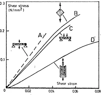
Results obtained by Basu from alternative tests to determine the shear modulus of the core material
Joined square shear test method Double shear test method
Different dumbells for tensile test to
DIN 430 and Iso 1926 81
3.8 Tensile test to DIN 53292 83
3.9 Dimension of the test specimen to BSI
4370 83
Chapter 4
4.1 Stress and strain distribution across
a plywood strip subject to bending 95 Chap ter 5
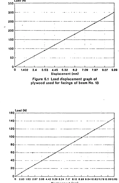
5.1 Load displacement graph of the plywood
facing used for beam No. 13 141
5.2 Load displacement graph of the plywood
facing used for beam No.1 141
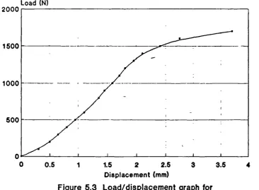
5.3 Load Displacement graph for styrofoam 142
5.4 4-point loading arrangement 145
5.5 Comparison of theoretical and experimental
deflection of beam Nos. 1 and 3 153 5.6 Comparison of theoretical and experimental
deflection of beam Nos. 4 and 5 154 5.7 Comparison of theoretical and experimental
deflection of beam Nos. 8 and 10 155 5.8 Comparison of theoretical and experimental
deflection of beam Nos. 11-15 156 5.9 Example of deflection and stress resultant
obtained by Stamm and Witte analysis 157 Chap ter 6
6.]. Heat transmission in a honeycomb core 161 6.2 Manufacturing methods of honeycomb 163 6.3 Comparison of honeycomb sandwich beam
with an I beam 165
Chap ter 7
7.2 Hypothetical force direction in fibre network for tensile loading along paper
material direction 180
7.3 Tensile test specimens 183
7.4 comparison of stiffness power of various
coatings 191
7.5 Stress vs. strain for various coatings 192 7.6 Stress vs. strain for sodium silicate
coating 193
7.7 Stress vs. strain for sodium silicate
coating and ball clay coating 194 chap ter 8
8.1 Comparison of experimental and theoretical
honeycomb core shear modulus 215 8.2 Honeycomb shear modulus as a function
of t/l*E 215
8.3 Typical honeycomb cell 219
Chap ter 9
9.1 Time/temperature graph to BSI 476 part 227 20
9.2 Blanking panel forming the door of the
furnace 231
9.3 Output graph for test panel with expanded
polystyrene foam core 247
9.4 Output graph for test panel with styrofoam
core 248
9.5 Output graph for test panel with mineral
wool core 249
and V 258 9.10 Cold face temperature for test panel L 260 9.11 Comparison of filled and unfilled panels 263 9.12 Output graph for test panel p 265 9.13 Cold face temperature for test panel S 268 9.14 Sandwich core with new configurations 276
App endix C
Cl Load elongation curve for stiffened
telephone directory paper 300
C2 Load elongation curve for stiffened
Kraft paper' 300
App endix D
LIST OF PLATES
Plate Chapter 5
5.1 The arrangement of the beam in the mould 139 5.2 Test arrangement and the method of
applying the load 144
Chap ter 6
6.1 scanning electron microscopic (S.E.M.)
of paper treated with sodium silicate 170
6.2 S.E.M. of paper treated with sodium
silicate and latex 172
6.3 S.E.M. of paper treated with sodium
silicate and ball clay 174
6.4 S.E.M. of paper treated with sodium
silicate and vermiculite 176
Chap ter 7
7.1 S.E.M. of untreated paper 179
chap ter 9
9.1 Intumescence foam filling the the space
occupied by the honeycomb core 234 9.2 Shrinking of the Intumescence foam 234 9.3 Honeycomb core treated with sodium
silicate and ball clay 237
9.4 Honeycomb core with vermiculite as filler 237 9.5 Honeycomb core cell walls reinforced with
vermiculite and sodium silicate 252 9.6 strength retention at high temperature
of honeycomb core treated with sodium
silicate and ball clay 252
9.7 Test panel C with filler composition of
cement and perlite 255
9.9 Expansion of the.cell wall material
ACKNOWLEDGEMENTS
I would like to express my deepest gratitude to my supervisor professor J.M. Davies, for his valuable advise and support throughout the project and during the preparation of this thesis, and Dr. J.B. Mchnicholas for his encouragement and guidance throughout the period of study.
DECLARATION
None of the material contained in this thesis has been submitted in support of an application for another degree or qualification of this or any other university
or institution of learning.
ABSTRACT
The research is divided into two parts. In the first part the structural behaviour of sandwich beams using timber-based facings and foamed plastic cores was studied. Various available theories were examined and the most appropriate theory for this type of panel was identified. In an extensive test programme the relevant properties of the constituent materials were measured and the data used in the proposed theory of structural behaviour to predict beam deflections and core and facing stresses. Corresponding sandwich beam tests were carried out on the range of skin/core combinations and the theoretical and experimental behaviours were compared. Good agreement was confirmed within the range of span/depth ratios investigated, confirming the applicability of the theory for semi-thick timber-based facings. A variety of timber based facings were investigated and those most suitable for sandwich construction were identified.
This type of panel construction has many advantages but lacks the benefit of good fire resistance. The recF.iired fire resistance could be provided by a suitable core material.
smoke and toxic fumes. Coated paper honeycombs were chosen for the study. The properties of the constituent materials were investigated in detail and then the
CHAPTER 1
GENERAL INTRODUCTION
AND
CHAPTER 1 1.1 HISTORICAL REVIEW
The first broad scale application of structures built on the sandwich principle dates back to world war two where extensive use was made of Birch facing material laminated to balsa wood core in the de Havilland "Mosquito" bomber 1 . Later in the war, drastic increases in air speeds and a concomitant requirement for aerodynamically smoother surfaces added interest. Finally, the sharp growth after 1945 in the size of both commercial and military planes spurred the efforts to reduce airframe weight and intensified the work on sandwich materials. Today, sandwich panels in aircraft use glass or carbon-fibre composite skins separated by aluminium or paper-resin honeycombs or by rigid polymer foams, giving a panel with enormous specific bending stiffness and strength. Most recently a diffusion-bonded titanium honeycomb core has been developed for the components of jet engine ducts and casing where it provides significant weight reductions compared with solid titanium2.
In building construction the use of sandwich panels is not new : Le Maison du peuple at Clichy, by Jean Prouve completed in 1939 is an early example. Prouve used a spring to separate the steel skins to achieve a light weight rigid component.
material composed of asbestos-cement board facing on laminated vegetable fibreboard core was applied extensively to defence and military housing in the United States 3 . More recently, cladding panels have been manufactured using a variety of materials. Facings have utilised metal sheeting, particularly steel and aluminium, plastics, plywood, or a variety of compressed fibreboards and various cement-based sheathing boards. There has also been some application for deeply profiled sheathing as facing. The main contrast with earlier sandwich applications is that facings are much thicker and, in many cases, composed of semi-brittle or less ductile materials. In most applications the core material also serves as thermal insulation. Polystyrene slab or rigid urethane foam materials are commonly used. Metal honeycomb core was used in the early applications of sandwich construction which provided strong yet light structural forms.
response of the honeycomb is fortuitously close to the analytical assumption of weak longitudinal stiffness and transverse incompressibility. Modern materials also provide light construction and have the added advantage of excellent thermal insulation properties. However, there have been lagging interest and slower progress in the building industry. Composite cladding panels only became available commercially in the 1970s, when the 1973 energy crisis emphasised the need to conserve fuel. Thus the thermal performance of the building envelop became much more important. The Sainsbury centre designed by Foster association 4 in 1977 incorporated one of the first rigid plastic foamed core and aluminium skin insulated composite cladding panels.
1.2 DEFINITION
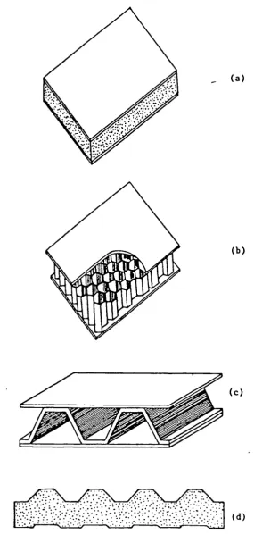
Sandwich structural members are made up of two stiff flat or corrugated skins separated by a thick layer of much weaker and lower density material. The skins or face materials are usually made up of high strength, stiff materials such as steel, aluminium, plywood, or fibre-reinforced composite; the cores are are made up of polymeric foams or aluminium or paper-resin honeycombs which are bonded to the faces (see fig 1.1 ). The core must be stiff enough to keep the faces at the required distance apart and it must also be stiff enough in shear so that when the panel is bent the faces do not slide over each other.
1.3 DESIGN ADVANTAGES
Sandwich panels are now extensively used in building construction. They owe their success to the following properties :
1. Good strength to weight ratio, i.e.,more strength for less weight of the materials involved in it's construction.
2. Optimum heat insulation values and assembly with no thermal bridges.
3. Their good sound insulation compared to homogeneous wall or roof elements of the same weight.
- (a)
(b)
(c)
[image:27.595.144.430.60.670.2]_____ (d)
rapid construction and ease of handling and assembly.
5. Provision for dismantling and re-erecting at any time; provision for extensions.
1.4 DESIGN LIMITATIONS
Sandwich panels are not without their problems and have less good properties. Their disadvantages are summarised in the following :
Sandwich panels using a plasic rigid foam core do not reach a notable fire resistance time. Here, resistibility to fire is defined as the ability of a building component:
a)_ to resist the passage of fire through a wall or roof for a specified time. b)_ to avoid temperatures in excess of
140 0 C above ambient temperature to occur on the unexposed side.
C)_ to maintain it's loadbearing capacity in the case of loadbearing panels and not to collapse in the case of non loadbearing panels.
d)_ not to evolve combustible gasses.
Other limitations inherent in modern day sandwich panels containing plastic cores are:
process of some rigid plastic materials. 2. Creeping behaviour under permanent load with
roof panels.
3. Temperature loading due to the high thermal insulation provided by the foam plastic. 4. Delamination (blistering) of metal face from
1.5 REVIEW OF RELATED STUDIES
usually in terms of polynomial or fourier series. Both methods give exact solution for the simplest problems. For more complex cases, the direct equilibrium/compatibility approach relies on the prescription of simplifying assumptions to make the solution more manageable. The latter variation methods allow a rigorous solution to complex problems, but are in a sense approximate in nature on account of the specification of an initially assumed displacement shape.
of the core in shear. The term very thin face is required to describe the situation where facing thickness is so small as to have little effect on core distortions.
The initial work on sandwich beams was carried out at the United States Forest Products Laboratory in 1940's. March and Smith 6 evaluated the total central deflection of a simply supported sandwich beam with thin flat faces. The deflection at the centre of a simple beam carrying a single load P was evaluated as:
WL3 WL
A = + (1.1)
48D 4AG
The total deflection was shown to be composed of two parts, the first being the contribution of ordinary bending displacement, the second due to shear strain in the core. The parameter D in the equation (1.1) refers to the flexural rigidity (El) of the sandwich as a whole. The parameter A reflects the shear action in the core and is the net core area. The term AG describes the core shear rigidity.
Norris et a1 7 approached the analysis in a different way, using a direct engineering equilibrium approach. This was successfully applied to include thick face action giving a deflection equation of the form
WL 3 WL If
A = + (1- )2(l_*) ...(1.2)
the first term in brackets represents the alteration to the average shear stress in the core imposed by the bending stiffness of the facing. The function • represents the reduction in beam flexibility resulting from the extra thickness of the facings bending about their own axes in reaction to core shear displacements. Norris presented a general solution method applied to beams with three or four point loading with overhangs. The thick face equations are, however, complex in application and later authors Kuenzi 8 ' 9 (1951), Howard1° (1962), and Doherty et a1 11 (1965) based their studies on performance testing of sandwich beams and comparison with the March and Smith equation.
different spans, the results being presented in two different formats to evaluate separate property components. With reference to the March equation (1.2) a graph of A/WL2 against l/L 2 separated out the shear stiffness in like manner. Comparison with small scale material property tests showed reasonable agreement for thin aluminium skins, and poor agreement for thick asbestos cement skins.
Allen 12 applied himself directly to the problem of testing beams with predominantly thick faces. He adopted a Doherty et al approach of multiple testing but discussed fully the implications of thick face action in relation to a new theory of analysis. The Allen theory is presented fully in a book 13 (1969) devoted to the bending and buckling analysis of sandwich beams and plates and further development in a later paper14(l973). Adams and Wienstien 15 (1975) developed the Norris and Allen approach, producing an analysis which included the contribution from core bending in the solution. The format of the analysis also provided direct insight into the nature of core and face interface bond stresses. Ogorkiewicz 6 ' 7 ' 18 ' 19 and others (1967-73) used the March theory to underpin several programs on the testing
with thin rubber cores.
1985,1988 discussed the analysis of sandwich panels on the basis of Allen's formulations for sandwich beams with thick faces. The author considered responses within the regions of the concentrated load and established the critical span concept where the effect of the point load disappeared at an identified distance away from the point load.
Stamin and Witte 30 (1974) presented formulations to assist the design of sandwich elements for building construction. Since this work is not available in English, Davies 31 (1986) has represented the basic equations and the most important solutions. The Stamm and Witte method is used to predict the behaviour of the sandwich beams described in chapter 5. In order to check the accuracy of the calculations, the results of the sandwich beams tested as part of the program (see chapter 5) are compared with the calculated results in chapter 6.
1.5.2 MECHANICAL PROPERTIES OF HONEYCOMB CORES
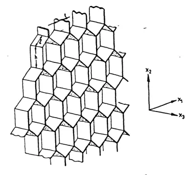
Man made paper, metal and ceramic honeycombs are now available as standard products. Paper and metal ones are used for the cores of sandwich panels in everything from cheap doors to advanced aerospace components and ceramics for high-temperature processing (e.g. catalyst carriers). If honeycombs are to be used as cores in sandwich panels it is important to understand their mechanics and since honeycombs have a regular geometry their deformation can be analysed to give equations to describe their mechanical properties. Honeycombs have two different sets of properties, in-plane and out-of-in-plane. The in-in-plane stiffness and strength (X 1 -X 2 direction in fig. 1.2) are the lowest because the stress in X 1-X 2 plane makes the cell walls bend. The out-of-plane strength and stiffness (in X3 direction) are much larger because the stress in X3 direction will result in axial extension or compression of the cell wall. It is the out-of-plane properties of honeycomb which are needed for the design of the honeycomb core in sandwich panels.
L3
1.5.2.1 THE CALCULATION OF HONEYCOMB SHEAR MODULUS
Kelsey and others 32 (1958) obtained expressions for the upper and lower limits to the shear modulus (Ge) of honeycomb sandwich cores made up of foil by application of unit displacement and unit load methods in conjunction with simplifying assumptions as to stress and strain systems in the core. In this work the shear modulus is expressed by the equation
2 K12
G = K 11 = (1.3)
K22
Where the symbols K denote stiffness's which are functions of the core geometry and material and subscripts 1 and 2 refer to two mutually, perpendicular directions. The term K 12 2 /K22 takes into account shear displacements which are not in line with the applied force.
Kelsey and others 32 used two methods to calculate the stiffness quantities necessary to determine G. The first method yields a lower limit solution for G and can be explained as assuming a sandwich having faces of zero bending stiffness. The second method yields an upper limit solution for G and can be explained as assuming a sandwich having rigid faces in bending.
different directions to include the effect of the core cell angle (a) and the aspect ratio (h/i) (see fig 2.9) of the core cell walls making use of the unit displacement method from equilibrium considerations. Their method was in parallel with Keisey and others32 except that Chang and Ebcioglu neglected the shear displacements which where not in line with the applied shear force since these displacements are generally small. Equation (1.3) therefore simplified to the following form
Gc = K 11 (1.4)
Penzien and Didriksson 34 (1964) examined the problem of predicting the effective shear modulus of honeycomb core materials and included in the analysis the effects resulting from boundary conditions which prevent warpage of the cell. They showed that these warpage constraints have little effect on the shear modulus except when the ratio of core cell length to it's lateral dimension becomes relatively small.
Gibson and Ashby 35 (1988) simplified the method used by Kelsey and formulated upper and lower bounds for the two shear moduli and if the two coincide, then the solution is exact.
1.5.3 DEVELOPMENT OF FIRE RESISTANT PLASTIC RIGID FOAMED CORE
Plastic rigid foams are being increasingly used in cores of sandwich construction. They owe their success to their low thermal conductivity, high ratio of strength to weight and low moisture 8bsortion. However, being organic materials, they can burn. When they are heated, smoke and toxic gasses can be evolved during smouldering and at some initiating temperature depending on the oxygen supply, they can undergo flaming combustion which result in new and sometimes dangerous degradation products.
Considerable work has been done in trying to reduce the ignitablity and to improve the fire resistance capacity of foams. Polystyrene was discovered in 1839, but it was not developed commercially until 1930 when much activity in developing foamed polystyrene started in several countries : for example, extrusion of foamed polystyrene in Sweden in 1931; Dow chemical Co. also developed independently styrofoam in the US; BASF in Germany investigated many techniques in the l930s and during the 1939-45 war and in the 1950s introduced a process using expanded polystyrene granules containing a solvent blowing agent.
degradation. Madorsky 37 (1962) later found that with polystyrene heated to a higher temperature (about 370°C) a different degradation mechanism predominates which greatly influences the gaseous products. Polystyrene foam will soften at 1000 c and dripping occurs at the temperatures associated with combustion. Attempts have been made to eliminate dripping of polystyrene foam by Linderman 38 (1969) by incorporating glass fibre , but this tends to reduce the fire rating according to some methods of evaluation because the polystyrene no longer
flows away from the flames. Briggs 39 (1984) stated that this melting-back mechanism can provide a useful safety control since it delays ignition, particularly if heat has to pass through poor conducting facings (e.g. plaster, concrete). Melting back leads to rapid failure in fire resistance tests (e.g. BS 476, part 22 etc.) since no direct link is maintained between the exposed face and the molten surface of the foam. Polystyrene foam can cause molten drips (especially in ceiling applications) and with some formulation these drips burn. However many polystyrene foams now contain brominated fire retardants which delay ignition of the molten polystyrene.
layer mineral. The fire performance of such products was reported to be greatly improved compared with conventional expanded polystyrene products. The modified polystyrene does not melt or drip prior to and/or during burning, and whilst the polystyrene may burn out, there remains an inorganic structure of a foam-like appearance.
However the desirable physical properties of conventional expanded polystyrene such as their toughness and light weight were reported to be adversely affected.
world represents the major outlet for PUR rigid foam. Foamed plastics are, however, regarded as a fire hazard and the need to improve the fire performance of both rigid and flexible PUR foams has been accepted.
Reich and Levi 41 (1967) point out that various degradation reactions are likely to occur when PUR foams are heated, the dissociation being firstly to isocynate and alcohol with side reaction due to further degradation of the isocynate, and then interaction between the isocynate and some of its degradation products and oxidation if air is present. Concerning the polyol component of PUR, Saunders 42 (1967) pointed out that polyester segments have lower heats of combustion than polyether segments, and are more suitable for producing thermally stable PUR. Nicholas and Ginitter43 (1965) reported an apparently higher melting point (mechanical stability up to 2000 c) by fire forming a cyclic trimmer of toluene disocyanate, which is termed an isocyanurate, to produce a foam but did not give any data on thermal stability at higher temperature.
Polyisocyanurate (PIR) foams were developed in 1968 with the following advantages over conventional rigid PUR foam :
l_ Higher operating temperature.
2_ improved surface spread of flame resistance. 3_ reduced ignitablity.
5_ improved fire resistance in composites compared to conventional urethane foams.
The improved performance of PIR foams in resistance to proposed torch and fire resistance tests is due to the formation of a Carbonaceous fibrillar network as a facsimile of the original foam structure. Once formed this char is destroyed only slowly and it act as a flame and heat barrier.
Phenolic foam were first produced in about 1945 and it was in the late l960s and 1970s that they were evaluated
1.5.4 SIMULATED FIRE TESTS ON SANDWICH PANELS
Early simulated fire tests on sandwich panels were conducted by Kaplan 47 , et al. (1965) on roof deck assemblies. Rigid plastic foam was sandwiched between a metal face and a bituminous membrane in a full scale structure about 30 x 7xn, and a standard exposure fire maintained at one end. The test was not strictly concerned with sandwich panels and the main purpose was to check whether the plastic foam would limit leakage of molten bitumen. The system was found to be acceptable for many applications except for large roof areas of industrial building where an additional layer of inorganic board was required between the metal face and the plastic foam.
were associated with sandwich panels except that slow propagation occurred in the polystyrene core of one of the tests.
During 1970 several manufacturers sponsored full scale fire tests at the Joint Fire Research Organisation49. Different panel systems were used for cladding three single-storey steel framed buildings. Two of the systems included foamed polyurethane cored panels with steel skins. One of the later systems was constructed with and without an air gap in the cavity between the steel
faces. Flame spread occurred in the panels only where there was an air cavity. Results on smoke and toxic gas measurement indicated that there was no additional hazard associated with sandwich panels compared to an acceptable lining system of steel cladding, mineral wool insulation, air gap and an internal lining of treated organic fibre insulating board.
A similar test was conducted in Australia during 1970 sponsored by the Plastic Institute of Australia 50 . A
sandwich panelled house was compared to similar timber framed house. Structural performance, smoke and toxic gases were monitored and indicated that the panelled house did not present a greater hazard.
plastics fires out of which 34 of these fires were in buildings other than warehouses and manufacturing plants. Only two of these involved sandwich panels and both had internal skins of plywood. The cellular plastics involved in other fires were mostly unprotected and were ignited by welding or electrical faults. Insufficient information was available to relate the properties of foams, as determined by tests, to performance in fire. However as the result of these studies it was suspected that test data had little relation to what happened in the actual fires.
This work led to the sponsorship of a full-scale fire test known as the corner wall test, at the Factory Mutual Research 52 (1973). Various types of insulating wall and roof construction built on a large scale were tested using a timber crib ignition. The object of the tests was to determine the fire characteristics of full-scale buildings according to type of cellular plastics insulation and method of construction, with and without additional sprinklers. Both sandwich panels and spray-on foams were studied. The result of the tests indicated that polyurethane foam and steel skins systems performed satisfactorily as walls for storage of noncombustibles without the aid of sprinklers. A similar polystyrene
system were found to require sprinkler aid.
or Polyisocyanurate cores failed in 3 to 6 minutes. However, the extra protection of 12 mm plasterboard or
intumescent mastic on the fire-exposed side provided a further 20 minutes of fire endurance.
Ashton 54 (1976), reported that expanded polystyrene used in cores of sandwich panels had virtually no influence on the stability of the panels. Tests demonstrated that 30 minutes stability could be obtained with certain timber frame and plasterboard facing systems and 60 minutes stability with certain steel and sheet-steel
facing systems.
Other work by "Imperial Chemical Industries",55 indicated that panels with polyurethane cores could retain integrity in model fire resistance test up to 120 minutes depending on the nature of the skin. Metal skins failed from as early as 13 minutes; 12 mm plasterboard on each face lasted about 40 minutes and systems with asbestos insulation board on both faces lasted 120 minutes. In these tests the polyurethane degraded and produced large amount of smoke, but the degradation had little influence upon the fire resistance of the system
galvanised steel), representing both cold-room and modular housing systems. Eleven sandwich panels were exposed for 10 minutes in a small furnace that modelled the Australian standard fire resistance test (As 1530 part 4. 1975). The authors reported that polystyrene used in cores of sandwich panels had no influence upon the dimensional stability of the panel. Polyurethane foam cores burnt wherever exposed but, in unexposed areas, degraded to a stable char remaining in place and retaining some insulation and mechanical value. Behaviour of the different types of facing varied considerably. The cellulosic facings offered little protection to the foam core. When they were exposed to the furnace they were rapidly consumed and allowed complete combustion of the foamed core. Asbestos/cellulose/cement facings warped, and when prevented from warping, cracked. The galvanised steel
facings warped and exposed the foam core.
In nearly all the above studies, hardly any attention has been given to the insulation performance of sandwich panels in the fire situation (i.e. the ability to avoid temperatures in excess of 140°C above ambient temperature on the unexposed face for the required time). They were all concerned with the integrity of the panels under investigation and their contributions to
1.6 THE BEHAVIOUR OP TIMBER PACE FACING
At this point it may be appropriate to digress a moment to point out the characteristics of wood as a construction material.
The character, orientation, and arrangements of wood fibres makes wood an anisotropic material. For all practical purposes, however, it may be treated as orthotropic, with three principal axes of symmetry, the longitudinal, the radial, and the tangential. The assumption of three structural axes result in a variable galaxy of properties :
Three Young's modulis : varying by 150 to 1, Three shear moduli varying by 20 to 1,
Six Poison's ratios varying by 40 to 1 and, Nine strength properties varying with grain direction (3 tension, 3 compression, and 3 shear).
The stiffness and strength are greatest in the axial direction, that is, parallel to the trunk of the tree; in the radial and tangential direction they are less by a factor of 1/2 to 1/20
The concept of wood as an orthotropic material with three principal axes of symmetry, and its widely different properties along and across the grain, involves a complicated mathematical problem in structural analysis.
an even more complicated material from the point of view of mathematical treatment.
1.7 FIRE RESISTANT SANDWICH CORE
Conventional sandwich panels with rigid plastic foam cores are being increasingly used as external wall and roof cladding for buildings. The panels often employ rigid plastic foam cores of polyurethane (PUR), polyisocyanurate (PIR), expanded or extruded polystyrene and steel faces. Since plastic foam materials are combustible, the steel-plastic foam sandwich elements are in principle also to be classed as combustible according to the requirements of for instance, building supervision of the Federal Republic of Germany57.
Fire resistant sandwich panels are available made with mineral wool cores but the incorporation of the mineral wool core for sandwich panels will result in increasing weight and cost of the panel. The mineral wool slabs are cut into strips of panel thickness perpendicularly to fibre direction in order to increase the tensile and compression strengths. Fire tests conducted at the University of Salford on sandwich panels with mineral wool core and aluminium alloy faces revealed that shrinkage of the strips caused opening up each joint in a V notch shape through which the heat was able to penetrate.
foaming process of some rigid plastic materials, will soon be forbidden, since CFC'S are considered to contribute largely to the destruction of the ozone shield. In Germany the use of CFC blowing agent will no longer be permitted after the end of l994. It was concluded that a novel core material was needed. The requirements for this new material were good fire resistance, adequate structural performance and an acceptable low density.
One such core material is based on a honeycomb construction. The structural requirement can be obtained via the honeycomb and fire resistance requirements can be obtained by filling the cells with non-combustible
insulating material.
requirement. It is to control the thermal shock properties by preventing the propagation of cracks through the ceramic phase and providing some flexibility to the overall structure.
Considerable success has been achieved in this manner. Both ballistic missile nose cones and rocket engine parts have been successfully fabricated and tested using material systems of this type59.
Burnett 60 (1960) has reported that, in addition to the oxide filled honeycomb structures, nitrides and carbides have been successfully fabricated into similar structures. A further development of this type of composite structure has been reported by Vogan and Trumbull 59 (1964). These structures were basically chemically bonded zirconia incorporating a novel metal honeycomb. Excellent thermal shock resistance for operation at 1300°C was obtained by selecting the proper honeycomb cell size.
The best system studied was reported to be a partially crushed honeycomb structure in which the honeycomb is bonded to desired backing material and partially filled with a fibrous insulating material. The remainder of the
CHAPTER 2
SANDWICH BEAM THEORY AND
CHAPTER 2
2.1 INTRODUCTION TO SANDWICH BEAM THEORY
Sandwich panels may be classified into two types for design purposes. The first is those with thin flat or lightly profiled types as shown in fig 2.la and 2.lb, and the second is those in which one or both faces are thick or heavily profiled (fig.2.2a and 2.2b). The
former type are used mainly for walls and the latter may be used for both walls and roofs in building construction.
For design purposes, it is necessary to consider panels with flat or lightly profiled faces separately from those with thick or profiled faces.
The structural analysis of sandwich beams with thin flat facings has been investigated as early as the 1940's at the United States Forest Products Laboratory. Two different approaches were evolved. The first one was based on equilibrium consideration and internal and external compatibility requirements. The second approach adopted variational methods where the equilibrium statement was defined in terms of stationary energy principles in order to reduce the governing system of partial differential equations to a corresponding system of ordinary differential equations.
(a)
----(b)
Figure 2.1 (a) Panel with flat thin faces (b) Panel with light profiled faces
(a)
(b)
was carried out by Hartsock 61 and Allen 62 ' 63 . They
presented methods for calculating deflection and
stresses in simply supported sandwich panels with thick
or formed faces. Allen 62 derived more general equations
for beam columns subjected to combined transverse and
edge loads using energy method. Stanuu and Witte 3 ° and
Davies 31 ' 64 developed solutions for sandwich beam
columns making use of equilibrium analysis.
In this chapter the analysis of sandwich beam with thin
flat faces using Allen's approach 13 is re-presented.
Then the analysis of sandwich beam with thick face
having different thickness and elastic modulus using
Stanun and Witte 3 ° approach for point loading is
re-presented and the solution is modified for four point
loading.
2.1.1 GENERAL ASSUMPTIONS
The stresses and deflections in a beam are found using
bending theory. The theory is based on the following
assumptions:
1.
The faces and the core are linearly elastic.
2.
There is adequate adhesion between the core
and the faces.
3.
The shear stress distribution is constant
over the depth of the core.
4.
Deflections are small.
contribution to the flexural rigidity of the sandwich.
6. There is no deformation of the core in the direction perpendicular to the core.
2.1.2 ANALYSIS OF A SANDWICH BEAN WITH THIN FLAT FACES : ALLEN'S THEORY12
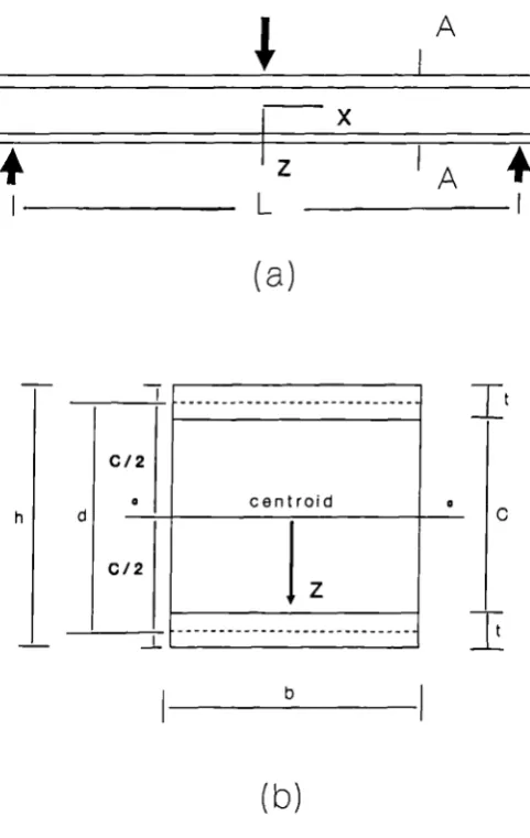
The overall flexural rigidity D of a sandwich beam (see fig. 2.3) is the sum of the flexural rigidity of the two separate parts, namely the faces and the core, measured about the centroidal axis of the entire cross-section thus
bt 3 btd2 bc3
D = Ef + E f +Ec (2.1)
6 2 12
where
E f is the Young's modulus of faces. b is the width of th beam.
t is the face thickness.
d is the distance between the centre lines of the opposite faces.
c is the core thickness.
4
AIx
4
jz
A4
I L I
(a)
It
C/2
a centroid
h d -- ____________
C/2
z
I
b(b)
[image:62.595.138.379.90.471.2]In sandwich beams with thin flat faces the flexural rigidity of the faces is very small in which case the second moment of area is negligible. The bending stiffness of the core amount to less than 1% of the second term and may consequently be neglected. The overall flexural rigidity is reduced to following :
D=
Ef.b.t.d2
(2.2) 2
The distribution of shear stress r throughout section
of a homogeneous beam has been modified to take account of the moduli of elasticity of different elements of the cross-section :
Q
E(SE) (2.3)
D.b
Where
Q is the shear force.
E(S E) is the sum of the products of first moment of area (s) and modulus of elasticity (E) of the different component of the cross-section.
The shear stress at level Z in the core of the sandwich in fig. 2.3 is therefore :
Q t.d E
7 = - Ef
D 2 2
c2
Q b.d
(2.6)
Q G.b..d
(2.7) The shear stress in the faces and complete shear stress distribution across the depth of the sandwich is illustrated in fig. 2.4a.
For a very weak core it is permissible to write E = 0 in the equation (2.4); the shear stress in the core is then given by
Q t.d
i' = - . E f (2.5)
D 2
In the case of sandwich beam with flat faces equation (2.5) is reduced to the simplest form :
This Shear stress in -the core is associated with a shear strain given by
where
G is the core shear modulus.
t
DI
t
b (a) (b) (c)
Figure 2.4 Shear stress distribution in sandwich beam. (a) Effect of weak core, neglecting the local bending
stiffness of the faces. (b) Effect of weak core.
(c) True shear stress distribution.
to the ordinary bending deflection, to give a total displacement of :
WL3 WL
AA 1+A2 = + ... (2.8)
48D 4AG
-where - -
-W is point load. -L is the span of the beam.
A, is centeral bending deflection
A 2 is central shear deflection A = bd2/C
2.1.3 ANALYSIS OF SANDWICH BEAN WITH THICK FACES STANM'S AND WITTE'S THEORY
The general principal of Allen's approach to the analysis of simply supported sandwich bea* with thin flat faces are initially presented. In this section analysis of a simply supported sandwich panel with thick faces of different thickness and modulus are re-presented using the Stainm and Witte approach. As this work is not available in English, Davies 30 has presented the basic equations and most important solutions which are re-produced here. The solution for a simply supported panel with point load any where on the span is presented and later the solution for a simply supported
2.1.3.1 GENERAL PRINCIPLES
The behaviour of a thick faced sandwich panel refers to the situation where the local bending rigidity of the
facings contributes significantly to the overall sandwich stiffness. The contribution of the thick face has two separate components.
Figure 2.6 shows the relevant stress resultant and deformation associated with a typical sandwich element under the effect of applied an load. The relationships between the stress resultants and deformations are
M1 = B1W
142 = -B 2 WI' (2.10)
M5 = B5(W111)
where
141,142 are the bending moments in the upper and lower faces, respectively.
B1,B2 are the flexural rigidities of the upper and lower faces, respectively.
M5 is the bending moment in sandwich part of the cross section.
Bs is the flexural rigidity of the sandwich part of cross section.
1
= A Geff Q1 = B1
1(1 = -B2 W
(2.11)
where
are the shear forces in the upper and lower faces, respectively.
Q is the shear force in the sandwich part cross section.
Geff is the effective shear modulus of core;= Gnom . D/Dc.
A = B.Dc
Since the stress resultants in the two faces are proportional to the same deformation, it is suitable to treat them together, thus,
MD = M 1 + M2
(2.12) H =MD+Ms
= Q 1 + Q2
q
- "lj°1Mi
D ID0 __+
M s°2 M2
(a) stress resultants (b) deformation element
BD i +
. . . (2.14)
B BD + B5
where -
-MD is the total moment in faces.
- M is total bending moment in the panel.
BD is the total flexural rigidity of the faces. B is the total flexural rigidity of the panel.
D is the total shear force in the faces. Q is the total shear force in the element
The total moment N and shear force Q may be found Using equations (2.10) and (2.11), thus,
Q = A•G y BD.W"
M = B5(Y+ 6) - B.W1
. • . .-. • (2.15)
Excluding Yand noting that Q1 = - q, a fourth order differential equation in W is obtained.
N
L L B a B ...(2.16)
- (._)2
'K,
Where :
BD a —
-Bs B5 B=
A.Geff L2
...(2.l7)
1+a a.fl
similarly, excluding W from (2.15)
(A) 2 1
L B
For statically determinate systems, solutions of (2.16) and (2.18) are :
. . . (2.18)
the general
Ax AX
W = C 1 cosh +C2 sixth
L L
(2.19)
Ax AX
Y =
cosh L + D2 sirth L + YWhere and are particular integrals which depend on the loading etc. As these- solution must satisfy
(2.15) it follows that
A
= (1+a) - C2 A D2 = (1+a) - C1
L
Stamm and Witte gave the solution of the above equations for simply supported panels subject to :
(a) uniformly distributed load. (b) point load.
(c) uniform temperature difference between faces.
The solution for a simply supported panel with a point load is re-presented in the following section and later it is used to derive the solution for simply supported sandwich panel with four point loading.
2.1.4.2 SIMPLY SUPPORTED BEAN WITH POINT LOAD P
Stamm and Witte 3 ° presented the following work as solution for the simply supported beam under point load. Figure 2.7 shows a simply supported beam with transverse load P at a position given by X = e. i.e. € = e/i
14
e
I . L
Figure 2.7
The bending moment and shearing force are determined by
P
N = - (L-e)x - P(X-e)°
L (2.21)
p
The particular integrals in equation (2.19) are then
W
P
- (L-e)X3 ^ L (x-e}
31-[
PL6BL
BA2
[
L
sinhA(X-e)/L
(L-e)X
+ -(Xe
-a
A/L
(X-e)°]
-A(x-e)
= PPL [
L-e-L(1-cosh -
(X-e)°
B L
..(2.22)
using index 1 valid for 0
c and index 2 for
€ ^
1
PL3 1
w1 = -
I
— (1-c) (2ec2)
+-B
L6
1 sinh A (1-c)
(1-c)- s1nhA
aA
3 sinhcA -J(2.23)
PL3 1 1
c2+2 2)_
w2=
[-;-€ (1-)(- - aA2
B
1
sinhAc
c(1-
U-a
3 sirthAsirth A (1- )]
PL3 sinh
A (1-E)
-
C + cosh AB
(2.24)
PL2
- p - c + coshA(1- U
3, r sirth A (1-c)
Msi = PL
I (1-6) -
sinhA ]1+a L BinhA
(2.25)
1 r sinhic
=PL Ic(1-F)- sinh (1-
F) ]
1+a L gjp
a
r
sinhA(1-e) 1= PL
1(1-c)
+ sinhA]14-a 1 aAsinhA
I
1(2.26)
a r sinhAc
MD2 = PL
Ic(1+)
+ sirthi (1-c)1-i-a L aAsjnhA
I j
1 r sinh A (1-c)
Qs1 P Ii- - coshA ]
14-a L sinh)
(2.27)
1 sirthA £
s2 = 1_c + cosh A (1- )
1+a
L
sinhAa sixth A (1-c)
- D1 = + cosh A
1+a a sinhA
(2.28)
a r sinhAc
D2 = [ 6 - cosh A (1-i)
2.1.3.3 SIMPLY SUPPORTED BEAM WITH FOUR POINT LOAD
The solution for single point loading presented in section 2.1.4.2 has been modified to suit a 4 point loading arrangement. For the 4-point load case, the calculation segments required to be assessed twice, each with opposite loads.
A Computer program was written to process the repetitive deflection and bending and shear stress calculations given in the above equations using a computer incorporating FORTRAN as the progranuming language.
By solving these equations twice, taking at first the left hand point load into consideration then the right hand point load and adding them. A solution for a four point loaded beam is achieved. The problem is
illustrated diagrammatically in fig. 2.8.
shear force diagram bending moment diagram
H-II
2.2 CALCULATING THE SHEAR MODULUS OF THE DEVELOPED HONEYCOMB CORE 2.2.1 INTRODUCTION
A Honeycomb is a two dimensional array of polygons which pack to fill a plane area like the hexagonal cells of the bees hive. Honeycombs are often used as cores in sandwich panels in applications where weight-saving is critical: in aircraft, in space vehicles, in portable structures and in sports equipment. The function of the honeycomb core here is to carry normal load and shear loads in planes containing the axes of the hexagonal prisms (the X3 direction as shown in fig. 1.2). In such a honeycomb construction, the shape and size of the cells and the thickness of the cell walls can be varied. A change in any of these may be expected to change the strength of the honeycomb.
The aim of this particular work was to present expression to relate the shear modulus of the honeycomb core under investigation to it's cell geometry. In order to demonstrate the accuracy of the analysis, the results of the calculations are compared with experimental work performed on the developed honeycomb core sandwich beams described in chapter 8.
The honeycomb-type structures used in this study were made by sodium silicate, or clay based sodium
2.2.2 CALCULATION OF SHEAR MODULUS
The distribution of stress in a honeycomb is not simple, according to Kelsey 65 ,Chang and Ebcioglue 66 and Penzein and Didriksson 67 , each cell suffers a non_uniform deformation due to the constraint imposed on it by it's neighbours and that the initial plane of the honeycomb may not remain plane. Exact calculation of the shear modulus is only possible by using numerical methods. Gibson and Ashby 35 derived upper and lower bounds for the honeycomb shear modulus by simplifying the method used by Kelsey et a1 65 .This was done by calculating the strain energy associated, first with a strain distribution which allows compatible deformation and second, with a stress distribution which satisfies equilibrium. The solution is exact if the two coincide and if not, the true solution lies between them.
Trin,viris direction
(a)
CI ZS
x2 LonQItudInal direction
4 -•
(b)
caused by a shear stress r 13 acting on the face normal to in the Xl direction of a unit-cell which repeats exactly to build up the entire honeycomb. The elastic strain energy is- stored in the shear displacement in the cell wall. The shear strain in the cell walls a,b and c (fig. 2.7b) are
-= 0
b =13cose . . . (2.29) •fc =13cose
The authors expressed the theorem as an inequality and gave the following form for shear in X 1 direction
1
2 - G13 13
2 •— i(G5 '2 Vj )
(2.30)
where
G5 = the shear modulus of the cell wall material.
= the shear strain in the three cell walls.
G 13 cos8 t
(4 (-)
G5 (h/1+sinO) 1
is... . . (2.31)
where
8 is the core cell angle. t is the cell wall thickness.
h,l are the core cell dimensions as shown in fig. 2.9b.
The calculation can be repeated for shear in the X2 direction. The shear strains in walls a, b, and c will be
= '23
'Y23sine . . . (2. 32) .rc = •r23 sin8
and
G 23 1 h/l+2sin2 e t
- (-) . . . (2.33) G5 2 (h/1+sinO)cose 1
The lower bound shear modulus was found by the authors using the principle of minimum complementary energy which states that among the stress distributions that satisfy equilibrium at each point and are in equilibrium with the external loads, the strain energy is a minimum
for the exact stress distribution. For shear in the direction the authors expressed the shear modulus as an
inequality
2 2
1
T,.,
T• (2.34)
Loading the honeycomb in X 1 direction will result in an external stress
r
13 which induce a set of shear stresses Ta
, T b and in the walls a,b and c respectively. By symmetry the shear stress in the wall b is equal to that in the wall c, and as the wall a is loaded in bending it carries no significant load (i.e. Ta 0). Equilibrium requires that2T 13 l(h+l.sine)cose = 2T b tl.cosO ...(2.35)
Combining equation (2.34)) with equilibrium equation (2.35) will give a lower bound for shear modulus:
cose t
(-)
...
(2.36)(h/l+sine) 1
Equations (2.31) and (2.36) show that the upper bound and lower bound shear modulus are identical indicating that the result is exact.
For a regular honeycomb h = 1 and 8 = 30. Therefore expression for shear modulus of a regular hexagons is reduces to the following form:
1
G13 Cs
G 13 - t
- 0.557 (-) G 5 1
If the honeycomb is loaded in X 2 direction, the external shear stress r 23 will induce a set of shear stresses Ta, T b and r in the walls a, b and c. Symmetry again
require the shear stresses in the walls b and c to be equal (i.e. T b =
Tc).
Equilibrium in X 3 direction means that
T a = Tb + = 2Tb
Equilibrium in X 3 direction with external stresses gives
2r231(h+l.sine)cose = 2Tb ti Sifl8+Tath ...(2.38)
1
so that Tb 23 cos8 - (2.39)
An expression for shear modulus in X 2 direction can be obtained by combining the inequality equation (eqn 2.34) with equations (2.38) and (2.39) as :
G23 h/1+sine t
(-) (2.40)
G5 (l+2h/l)cose 1
As equations (2.33) and (2.40) shows, the upper and lower bound shear modulus do not coincide for shear stress in the X 2 direction. But the bounds do coincide for a regular hexagons and both equations (2.33) and
(2.40) will be reduced to the following form
G 23 - t
- 0.577 (-) 1
The expression for the shear modulus of a regular honeycomb with shear stress in X 1 direction is identical with shear stress in X 2 direction (eqn (2.37) and (2.41)) indicating that regular hexagonal honeycombs are isotropic in the X 1 -X 2 plane.
CHAPTER 3
TEST TO DETERMINE MATERIAL
CHAPTER 3
TESTS TO DETERMINE MATERIAL PROPERTIES 3.1 INTRODUCTION
The physical properties of materials used in the construction of sandwich panels are important for two purposes :
For determination of certain parameters which must be known before design calculations. 2_ For quality control.
For the purpose of design analysis, only the former is concerned here. However, some of the test procedures may be identical for both purposes with different
interpretations.
The physical properties of the material required for the design of sandwich panels are:_
Core material :
shear modulus shear strength
tensile modulus of elasticity tensile strength
compression modulus of elasticity compression strength
tensile bond to face material creep factor
Face material :
yield strength wrinkling stress.
The above face material applies to homogeneous materials and when the face material is none homogeneous such as timber the required properties will be as follows :
Timber facing :
modulus of elasticity in bending modulus of rupture.
In this chapter description of the different standard test methods for rigid foam core material are presented, followed by previous work on shear properties, and finally the authors experimental work on physical properties of extruded and expanded polystyrene core will be discussed.
3.2 NOTATION A0 b C E5 F Ge cc h0 I L Fm, F10 T Ws Wb Xm, Xo
Initial cross section area in compression test.
Width of beam. Core thickness.
Young's modulus of face material.
Area of the specimen glued to the four steel plates in hinged shear test.
Loads at cell structure collapse and 10% deformation respectively in compression test.
Weight of sandwich beam. Core shear modulus.
Initial height in compression test.
Total moment of inertia of sandwich beam. Total beam span
Applied load in dynamic test.
Complete duration of back and front vibration in seconds
Deflection due to shear. Deflection due to bending.
Defection of cell structure collapse and 10% deformation respectively in compression test.
T Core shear stress.
6 Shear strain.
structure.
3.3 CORE PROPERTIES
In the design of sandwich panels the choice of suitable core materials is of particular importance. The low density core must be stiff enough in compression and shear in the plane perpendicular to the face to keep the faces fixed at. given distance apart and to ensure that the faces and core act as a composite section under loading.
The mechanical properties of rigid plastic foams are dependent on the apparent density, the cell structure and the manufacturing process. Figure 3.1 shows the tensile strength, compression strength and shear strength as a function of the apparent density of rigid polyurethane foam 68 . The cell structure also has a very significant influence on the properties. The cell structure can be described as a skeleton and walls, supporting the construction of the foam. Therefore, it is important that for each foamed core the physical properties should be determined before the structural analysis is carried out.
Strength (N/mm•2) 0.8
0.6
0.4
0.2
0 I I I I I
20 30 40 50 60 70
Density (kg/m.3)
Figure 3.1 Typical relationships between and density of