i
Graphite Immobilisation in Glass Composite Materials
Mohd Zul Hilmi Mayzan
A thesis submitted in partial fulfilment of the requirements for the degree of
Doctor of Philosophy
Immobilisation Science Laboratory
Department of Materials Science and Engineering
The University of Sheffield
ii
Abstract
v
Contents
Abstract ii
Acknowledgements iii
Published Work iv
1. Introduction 1
2. Literature Review and Theory 3
2.1. History, Current and Future Usage of Nuclear Technology 3
2.2. Commercial Nuclear Power Reactor 5
2.2.1. Main Components 7
2.3. Nuclear Wastes 10
2.3.1. High Level Waste 10
2.3.2. Intermediate Level Waste 11
2.3.3. Low Level Waste 12
2.4. Irradiated Graphite 13
2.4.1. Structure and Properties of Graphite 13
2.4.2. Production of Nuclear Graphite 16
2.4.3. Waste Origin and Volume 20
2.4.4. Radiation Effects on Graphite 21
2.4.5. Disposal Options and Challenge for the Waste Immobilisation 26 2.5. Processing Routes for the Immobilisation of Irradiated Graphite 28
2.5.1. Glass Materials 29
2.5.2. Microwave Processing 32
2.5.3. Cold Press Sintering Processing 33
2.5.4. Spark Plasma Sintering Processing 35
2.6. Summary 37
3. Materials and Experimental Methods 39
vi
3.2. Irradiated Graphite Waste Simulant 39
3.3. Microwave Processing 39
3.3.1. Experimental Setup 40
3.3.2. Sample Preparation 41
3.4. Conventional Processing 42
3.4.1. Batch Preparation 43
3.4.2. Glass Melting 43
3.4.3. Preparation of Powdered Glasses 45
3.4.4. Cold Press Sintering 46
3.5. Spark Plasma Sintering Processing 47
3.6. Particle Size Analysis 49
3.7. Thermogravimetric Analysis 51
3.8. Differential Thermal Analysis 51
3.9. Dilatometry 51
3.10. Chemical Analysis 52
3.11. Volume Shrinkage 53
3.12. Assessing Mass Loss 54
3.13. Density 54
3.14. Porosity 55
3.15. X-ray Diffraction 56
3.16. Fourier Transform Infrared Spectroscopy 57
3.17. Microscopy 59
3.18. Raman Spectroscopy 62
3.19. Mössbauer Spectroscopy 63
3.20. Indirect Tensile Testing – Brazilian Method 65
4. Results and Discussion I: Graphite Immobilisation in Iron Phosphate Glass Composite Materials Prepared using Microwave and
Conventional Processing 67
4.1. Introduction 67
vii
4.2.1. Particle Size and Density 67
4.2.2. Effect of Heating under Air and Argon 68
4.2.3. XRD 69
4.2.4. FTIR 70
4.2.5. Microstructure and EDS Analysis 71
4.3. Characterisation of Iron Phosphate Base Glasses 75
4.3.1. Chemical and Physical Properties 75
4.3.2. XRD 76
4.3.3. FTIR 77
4.4. Characterisation of Iron Phosphate Glass Composites 78
4.4.1. Physical Properties 78
4.4.2. XRD 81
4.4.3. FTIR 82
4.4.4. Microstructure and EDS Analysis 83
4.5. Mössbauer Spectroscopy Analysis 88
4.6. Discussion 91
4.7. Summary 94
5. Results and Discussion II: The Production of Various Graphite-Glass Composites by CPS Method for the Immobilisation of Irradiated
Graphite Waste 96
5.1. Introduction 96
5.2. Characterisation of Base Glasses 96
5.2.1. Chemical Composition and Physical Properties 97
5.2.2. XRD 99
5.2.3. FTIR Spectroscopy 100
5.2.4. Raman Spectroscopy 103
5.3. The Effects of Sintering Temperature on Graphite-glass Composites 107
5.3.1. Volume Shrinkage 108
5.3.2. Mass Loss 109
viii
5.3.4. XRD 113
5.3.5. Optical Microscopy and Optical Profilometry 118
5.3.6. SEM and EDS 120
5.3.7. Mössbauer Spectroscopy 128
5.4. The Effects of Waste Loading on Graphite-glass Composites 130
5.4.1. Volume Shrinkage 131
5.4.2. Mass Loss 132
5.4.3. Density and Porosity 134
5.4.4. Indirect Tensile Testing 136
5.5. Discussion 137
5.6. Summary 142
6. Results and Discussion III: The Immobilisation of Simulant Irradiated Graphite in Calcium Aluminosilicate Glass Composites Using Spark
Plasma Sintering 144
6.1. Introduction 144
6.2. Sintering Profile of SPS 144
6.3. Sintered CAS Glass Prepared using CPS and SPS Methods 146
6.3.1. Density and Porosity 146
6.3.2. XRD 147
6.3.3. Optical Microscopy 148
6.3.4. SEM and EDS 149
6.4. The Effect of Sintering Temperatures on CAS30G Composites 151
6.4.1. Density and Porosity 152
6.4.2. XRD 154
6.5. The Effect of Sintering Dwell Time on CAS30G Composites 155
6.5.1. Density and Porosity 155
6.5.2. XRD 157
6.6. Microstructural Analysis of CAS30G Composites 158 6.6.1. Optical Microscopy and Optical Profilometry 158
ix 6.7. The Effect of Waste Loading on CAS Glass Composites 163
6.7.1. Density and Porosity 164
6.7.2. Indirect Tensile Testing 166
6.8. Discussion 167
6.9. Summary 171
7. Conclusions and Suggestions for Further Work 172
7.1. Introduction 172
7.2. Contamination of Graphite simulants in Graphite-glass Wasteforms 172 7.3. Graphite Immobilisation using Microwave Processing 173 7.4. Graphite Immobilisation in Various Glass Compositions by CPS 174 7.5. Graphite Immobilisation in CAS Glass Composites using SPS 176
7.6. Future Work and Recommendations 176
References 178
Appendix 194
1
1.
Introduction
The maintaining, decommissioning and dismantling of certain types of nuclear power plants used to generate electricity are mainly responsible for the production of problematic irradiated graphite wastes. Currently, the conditioning and disposal plan for the irradiated graphite waste remains unclear in all waste producing countries (i.e. UK, Russia, US, France). The major concern related to the irradiated graphite is the huge volume of the waste, which accounted worldwide about 260 000 tonnes and the present of long-lived radionuclides i.e. 3H, 14C, 16Cl. Historically relative little attention has been given to identifying a disposal strategy for irradiated graphite waste. The irradiated graphite waste now urgently requires disposal management solutions and this triggered interest in studying immobilisation methods that may be suitable for the production of irradiated graphite wasteform based glass materials.
A survey of the literature reveals several potential immobilisation methods that may suitable for the production of graphite glass composite wasteforms. This leads to the novel aim of the thesis; to investigate the potential of glass materials as a host for the production of irradiated graphite wasteforms prepared using unconventional and conventional processing methods. The aim can be divided into three primary research objectives as follow:
i. To assess the potential of microwave processing method for the production of graphite wasteforms using iron phosphate glass.
ii. To explore and assess the potential of conventional sintering in the production of graphite wasteforms prepared using various glass systems as a host.
iii. To investigate the potential of spark plasma sintering method for the production of graphite wasteforms using calcium aluminosilicate glass.
2 structure, properties, waste origin and problems arising from the irradiated graphite waste are reviewed. Attention is also given to recognise the suitability and materials processing techniques of microwave, conventional sintering and spark plasma sintering for the production of graphite-glass wasteforms.
Chapter 3 presents a description of graphite simulant and details about immobilisation methods used and processing methods employed throughout the preparation of graphite-glass composite wasteforms. All the basic principles of the instruments and the materials characterisation techniques conducted on the produced samples are explained in detail. This includes a variety of analytical techniques used such as particle size analysis, thermogravimetric analysis, differential thermal analysis, dilatometry, chemical analysis, volume shrinkage, assessing mass loss, density, porosity, X-ray diffraction, fourier transform infrared spectroscopy, microscopy, Raman spectroscopy, Mössbauer spectroscopy and indirect tensile testing – Brazilian method.
Results and discussion are split into three chapters and structured accordingly to each of the research objectives. Chapter 4 gives the characterisation results of graphite simulant, iron phosphate glass and composite wasteforms prepared using microwave as well as a comparison of potential microwave samples with samples produced using conventional sintering. Findings from Chapter 4 lead to the development of Chapter 5, which discussed the use of various glass compositions as a host to encapsulate graphite simulant. The iron phosphate glass composition is used as a baseline in comparing with the results obtained using other glass compositions namely alumino-borosilicate, calcium aluminosilicate, modified alkali borosilicate and obsidian. Based on Chapter 4 and 5, Chapter 6 was developed and specifically focuses on the production of low porosity graphite-glass wasteforms using calcium aluminosilicate glass. The obtained data were compared with the sample produced using conventional sintering.
3
2.
Literature Review and Theory
2.1. History, Current and Future Usage of Nuclear Technology
In 1932, James Chadwick discovered the neutron (Chadwick 1932). The next year Enrico Fermi found a much greater variety of artificial radionuclides was formed when using neutrons instead of protons as a source for bombarding the atoms. The history of nuclear fission started at the end of 1938, when Otto Hahn and Fritz Strassmann attempted to create transuranic elements by bombarding uranium with neutrons. They expecting heavy elements, however, the product produced from the experiment were lighter elements including 141Ba and others which were about half the mass of uranium. This result was interpreted by Lise Meitner and Otto Frisch working under Neil Bohr (Meitner and Frisch 1939); they suggested that the neutron was captured by nucleus and causing severe vibration leading to the nucleus splitting into two roughly equal parts which termed fission (essentially the fission of 235Uhad occurred). In 1939, Otto Frisch successfully confirmed that the fission of 235U yielded numerous amount of energy, ~200 MeV (Frisch 1939) and realised the potential of a fission chain reaction. This was the first experiment confirming the theory of Albert Einstein, which explained the equivalence between mass and energy, E = mc2 (Einstein 1905).
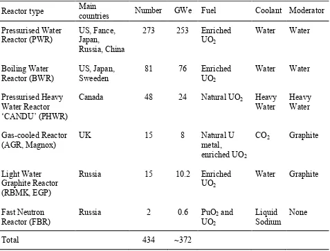
4 The new era of nuclear reactors used for generating electricity began in the 1950s and they have been improved ever since. The first nuclear reactor to generate electricity was built in a small scale by Argonne National laboratory, Idaho, USA in 1951. The reactor was called Experimental Breeder Reactor (EBR-1) and successfully powered four 100 W light bulbs. At present, more than 400 nuclear reactors are being used to generate electricity and the reference data of operated reactors connected to the grid at the end of 2013 is listed in Table 2-1. Note that the graphite is continuously used as moderator in current operated gas-cooled and light water graphite reactors.
Table 2-1: Nuclear power reactors in commercial operation, 31 Dec 2013 (IAEA 2014b).
Reactor type Main countries Number GWe Fuel Coolant Moderator Pressurised Water Reactor (PWR) Boiling Water Reactor (BWR) Pressurised Heavy Water Reactor ‘CANDU’ (PHWR) Gas-cooled Reactor (AGR, Magnox) Light Water Graphite Reactor (RBMK, EGP) Fast Neutron Reactor (FBR) US, Fance, Japan, Russia, China US, Japan, Sweeden Canada UK Russia Russia 273 81 48 15 15 2 253 76 24 8 10.2 0.6 Enriched UO2 Enriched UO2
Natural UO2
Natural U metal, enriched UO2
Enriched UO2
PuO2 and
UO2 Water Water Heavy Water CO2 Water Liquid Sodium Water Water Heavy Water Graphite Graphite None
Total 434 ~372
5 17.8, and 2.4 % for thermal (solids, liquids, gasses, biomass and waste), hydro and renewable (geothermal, wind, solar, tide) energy respectively (IAEA 2014a). The use of nuclear power reactors to generate electricity is gaining attention as it makes significant contribution to the mitigation of green-house gas emissions e.g. in 2009, it was claimed that the nuclear power reactors reduced by about 10 % of CO2 emission from the world energy consumption
(Adamantiades and Kessides 2009, Menyah and Wolde-Rufael 2010). Furthermore the use of a small amount of fuel, improved design of reactor and reliable energy source making the nuclear reactors favourable technology among the others in terms of generating electricity.
It is clear that the global plan is to reduce the CO2 emissions, minimise the green-house gases
and consequently decrease the amount of manmade global warming. This means that the use of coal thermal power plan will be further reduced and to meet the demand for electricity consumption that keeps increasing (global energy demand is estimated to increase by ~37 % by 2040), the use of nuclear, hydro and renewable energy is being increased (IEA 2014b). It is also evidence in the past (from 1973-2012) that the total global electricity demand is increased from 9.4 to 18.1 % (IEA 2014a). As a result, more nuclear reactors are being built and are planned to be built in the future. In 2013 alone, 77 nuclear reactors were under construction and 48 of those reactors were located in Asia (IAEA 2013). This is the highest number of reactors being constructed since 1989 and the figure is more likely to increase in the future, which may account for ~17 % of the global electricity production in 2050 (OECD et al 2015). Furthermore generation IV nuclear reactors (expected to arrive in ~2030) such as prismatic and pebble bed designed High Temperature Gas-cooled Reactor (HTGR) also utilise graphite as a reactor core and fuel matrix – tristructural-isotropic (TRISO) fuel and fuel pebble (OECD Nuclear Energy Agency 2014). Thus one can predict that more irradiated graphite will be produced in the future.
2.2. Commercial Nuclear Power Reactor
6 steam of which used to rotate the multiple blades in the turbine. The turbine is designed to minimise the energy lost and capable to condense the steam back into water so that the cycle could operate continuously. The kinetic energy created from the rotation of blades in the turbine is converted into electrical energy by a generator. Essentially, all the nuclear power reactors utilise similar concepts to generate electricity and schematics of the most popular commercial reactors to date is shown in Figure 2-1. Note that the turbine and generator parts of the reactors are not shown in the figure.
Figure 2-1: Schematic of currently used nuclear reactors, (a) PWR, (b) BWR, (c) PHWR/Candu and (d) AGR (taken from WNA 2015).
(a) (b)
7 2.2.1. Main Components
The nuclear power reactors currently used for generating electricity can be categorised into 2 types: fast and thermal (slow) reactors. Unlike the explosion of nuclear weapons, nuclear power reactors are meant to control the nuclear fission activity and sustain the nuclear chain reaction as well as maintaining the production of electricity in a long term condition; the expectation of lifespan is ~30-40 years. As evidenced in Table 2-1, the use of fast reactors (FBR) is less favourable compared to the thermal reactors (PWR, BWR, PHWR, AGR, Magnox, RBMK, EGP). The reason behind this is solely because fast reactors are difficult to build and very expensive to operate, although fast reactors are capable of generating ~60 times energy than thermal reactors. In spite of both reactors are technically different, most of the reactors components are largely similar and can be simplified as follows (Duderstadt and Hamilton 1976, Wilson 1996, IAEA 2007, Stacey 2007, Lewis 2008):
Fuel (fissile element) – The main difference between both fast and thermal reactors are the types of fuels. A fast reactor usually employs enriched 239Pu or enriched 235U (require about 20-30% of
fissile nuclei) core surrounded with 238U (fissionable/fertile element) blanket. This type of reactor generates more fuel than it consumes; this occurs because 238U has high probability to capture a fast neutron from the fission of 239Pu or 235U, neutrons induced by fission are then captured by 238U and consequently breed 239Pu as well as releasing two β-decays (Cochran et al 2010). The new generated 239Pu radionuclides can later be utilised as new fuel in future reactors. In contrast, thermal reactor mainly uses natural uranium (contained ~0.7 235U) or enriched 235U
(up to 5 % of 235U) fuel. Generally the fuel is fabricated into pellets, being vertically
arranged/stacked in a cladding tube (i.e. zircaloy, stainless steel, Mg alloy) called fuel rod and numerous fuels rod form the fuel assembly that specifically designed to be lifted into and out of the reactor core. To start the nuclear fission reaction, a neutron is captured by a fissile nucleus and the reactions occurring from 235U or 239Pu are given in Equation 2-1 and 2-2 respectively. Note that Equation 2-1 and 2-2 are the fissions caused by the thermal neutron without considering the energy from neutrinos.
MeV 9 . 192 (average) neutrons
2.4 fragments fission
neutron U
235
+ +
→
8 MeV
5 . 198 (average) neutrons
2.9 fragments fission
neutron Pu
239
+ +
→
+ [2-2]
Moderator – In a fast nuclear reactor, the use of moderator is not necessary because the reactor utilises fast neutrons to cause fission in their fuel. Due to the low probability of fission versus neutron capture, the highly enriched fissile fuel is used to sustain the chain reaction. However, in the thermal reactors, the fast neutrons (resulting from fission) must be slowed by the moderator; as fast neutrons (kinetic energy ≥ 1 MeV) are most likely to be captured by 238U, which is non-fissile. Only the thermal neutrons (kinetic energy < 1 eV) have a high cross-section (probability) to efficiently maintain and sustain the fission reaction of 235U. Theoretically, the neutrons are slowed by collisions with nuclei of about similar mass and these materials are not neutron absorbers. The common moderators used to date are ordinary water and purified graphite as well as the most excellent one but expensive heavy water. For gas-cooled nuclear power reactors i.e. AGR and Magnox, purified graphite is the most suitable material and widely used as a moderator. In fact the voluminous irradiated graphite waste largely originates from moderator part of nuclear power plant.
Control Rod – The purpose of control rod is to maintain the rate of fission chain reaction, so that the nuclear power reactor achieves criticality and operates at a steady power level. To control the rate of fission reaction, neutron-absorbing materials whose nuclei absorb neutrons without undergoing any addition reaction, such as B, Cd or Hf are used for the production of control rods. The control rods are being inserted or withdrawn from the reactor core to control the number of the neutrons; absorbing more neutrons means that less neutrons are available for nuclear fission, thus inserting the control rod deeper into the reactor core will reduce the power output of the nuclear reactor and vice versa. The control rod is also used to halt the nuclear power reactor by absorbing all the neutrons to stop the fission reactions.
9 cooling problems, thus a more efficient coolant such as liquid Na or Pb is used. In thermal reactors, ordinary water, heavy water (water usually pressurised to maintain at liquid phase) or CO2 gas are commonly used as a coolant. All the thermal reactors except BWR type separate the
cooling system from the water that will be boiled to produce high pressure steam.
Pressure Vessel or Protective vessel – Fast reactors do not utilised pressurised coolant, thus the protective vessel is used as containment for its coolant and reactor core. In the thermal reactors, a steel pressure vessel (PWR, BWR, AGR, Magnox) or pressure tubes (PHWR) is used to hold the circulated pressurised coolant as well as acting as containment for the moderator, control rods (except PHWR) and reactor core (see Figure 2-1). The pressure vessel/tube or protective vessel also worked as the first layer of shielding; preventing most of the radiation and radionuclides from leaching out to the biological environment. In some cases, a reflector is installed inside the vessel or surrounding the core to reflect the scattered neutrons back to the reactor core (Duderstadt and Hamilton 1976); this increases the efficiency of the fission of the fuel and at the same time protects the vessel from neutron induced damage which decreases the lifespan of the vessel. Characteristically, the reflector possesses similar properties to the moderator and sometimes similar materials serve a dual purpose in the nuclear power reactor. The most common material used as a reflector is graphite.
Steam Generator – This component is specifically designed as a heat exchanger, which converts water into steam. The steam generator is constructed separately in fast and thermal reactors. Only BWR (thermal reactor) boils the water in a pressurised vessel and directly uses steam generated in-situ by this process.
10 materials. Typically, a metre thick reinforced concrete or steel/lead structure is used as containment and shielding in current commercial reactors.
Turbine and Generator – The turbine and generator are the key components to generate electricity from the nuclear energy and these components are being installed in all types of commercial nuclear reactors. In practice, the high pressure steam turns the turbine and the generator converts the produced mechanical energy to electrical energy by using an electromagnetic field. The produced electrical energy is then manipulated by the transformers, connected to the grid and supplied to the consumers.
2.3. Nuclear Wastes
Nuclear power reactors are a mature technology and have been proven safe while generating reasonably clean electrical energy. The drawback of using nuclear power reactor is the fact that the nuclear reactor creates significant amount of radioactive waste from the fission process. The decay process of the waste emitting α, β and γ radiation can take up to millions of years. This is problematic as within this time period the nuclear wastes must be isolated from biosphere; the migration of the radioactive materials to the biosphere causes adverse effects and is highly hazardous to all biological systems/organisms. Therefore the nuclear waste must be treated with an appropriate fashion, stored in properly engineered storage facility and must not impose undue burden for future generations (IAEA 2011). The classification of the nuclear waste depends on the waste management policy of each waste producing country, typically taking account of the radiation levels, decay activity and disposal issues. In this study, the classification of the waste, characterisation and the waste disposal management will be based on the current UK regulations and policies. The radioactive wastes in the UK are divided into three categories and the details are as follows:
2.3.1. High Level Waste
11 or disposal facilities” (Her Majesty’s Stationery Office 1995). Within the UK, HLW mainly existed in liquid form and is a by-product from the reprocessing of spent nuclear fuel; the process is carried out at Sellafield and will continue until 2018 (NDA and DECC 2013). Due to the heat generated and very high radiation levels, the HLW liquid requires continuous engineered cooling and substantial shielding. In order to increase the efficiency of the nuclear fuel cycle, the spent nuclear fuel reprocessing is aimed at recovering/extracting the (re-)usable uranium and plutonium. The extracted uranium and plutonium are later being recycled for the production of new fuel called mixed oxide (MOX) fuel. For immobilisation, the HLW liquid is calcined to become solid, mixed with alkali borosilicate glass frit and is converted into homogeneous glass by a vitrification process, poured into a stainless steel canister after which a lid is welded onto it (~150 litre capacity) and stored in an engineered air-cooled facility at Sellafield for at least 50 years to allow the reduction of radioactivity by natural decay processes; the current plan for final disposal of the HLW canisters is long term disposal in a geological disposal facility (Ojovan and Lee 2005, CoRWM 2006, Defra et al 2008, NDA 2009, DECC 2014).
2.3.2. Intermediate Level Waste
12 2.3.3. Low Level Waste
Low Level Waste (LLW) is defined as “radioactive waste having a radioactive content not exceeding 4 GBq per tonne of alpha or 12 GBq per tonne of beta/gamma activity”; a sub-category of LLW is Very Low Level Waste (VLLW), which is split into two groups according to the specific disposal method as follows (Defra et al 2007):
• Low volume VLLW (dustbin loads) – Defined as “radioactive waste which can be safely
disposed of in an unspecified destination with municipal, commercial or industry waste (dustbin disposal), each 0.1 m3 of waste containing less than 400 kBq of total activity or single item containing less than 40 kBq of total activity”. With respect to VLLW that contains 14C and 3H, the activity limits from both radionuclides is 4000 and 400 kBq in each 0.1 m3 and for any single item respectively. No controls on disposal are needed when removing these wastes from premises to a disposal site.
• High volume VLLW (bulk disposals) – Defined as “radioactive waste with maximum
concentration of 4 MBq per tonne of total activity which can be disposed of to specified landfill sites”. The concentration limit for waste containing 3H is 40 MBq per tonne. Controls on disposal specified by the environmental regulators are required when removing these wastes from premises to a disposal site.
13 2.4. Irradiated Graphite
Irradiated graphite is a problematic waste resulting from the long term exposure of nuclear grade graphite or purified graphite to neutrons and mainly originates from gas-cooled nuclear power reactors. Currently, all the irradiated graphite waste producing countries have raised significant concerns about the management and disposal routes for the irradiated graphite waste. It is also worth mentioning that at present, there is no ideal solution for the final disposal of irradiated graphite (IAEA 2006, 2010). In addition, the complexity of irradiated graphite waste usually makes the handling (dismantling during decommissioning), transportation and waste packages challenging. Although the literature on the immobilisation of irradiated graphite waste is limited at the time being, in this section, it is intended to discuss the available literature about nuclear graphite, which includes the structure and properties of graphite, production of nuclear graphite, waste origin and volume, radiation effects on graphite and finally challenges for its waste immobilisation and disposal.
2.4.1. Structure and Properties of Graphite
14 Figure 2-2: Hexagonal unit cell of graphite, space group: D4 P63 /mmc
h
6 − (Pierson 1993).
Figure 2-3: Rhombohedral unit cell of graphite, space group: D5 R3m
d
3 − (Reynolds 1968). co
= 0.6708 nm
ao = 0.245 nm
B A
A
co
= 1.006 nm
A
C
B
A
[image:21.612.164.442.398.653.2]15 The hexagonal (alpha) structure of the graphite is thermodynamically stable and it is the commonest structure. In contrast, the rhombohedral (beta) graphite structure is thermodynamically unstable and the form is best known as an extended stacking fault of hexagonal graphite. The rhombohedral graphite is never found in the pure form and always exists in combination with hexagonal graphite. Normally natural and synthetic graphites contain a proportion of rhombohedrally structured material of which the amount found is typically less than 40 % (Pierson 1993, IAEA 2000). It is worthy of note that the content of rhombohedral graphite can be increased by grinding (shear deformation) and can also revert progressively to hexagonal graphite by heat treatment above 1300°C (Pierson 1993, IUPAC 1997).
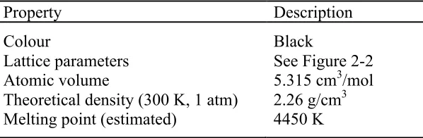
[image:22.612.158.457.527.625.2]As mentioned previously, graphite is used in the nuclear industry due to its capability to reduce the kinetic energy of fission neutrons by collisions (moderator in Section 2.2.1) and it has a low neutron cross-section i.e. the value is around 3.5-3.8 mb for pure nuclear graphite (Nightingale 1963). In addition, the properties of graphite such as being strong enough for structural components (produced by extrusion or vibration moulding or isostatic pressing), having good machinability, being stable and certified as one of the most inert materials make it highly attractive as well as suitable for many nuclear applications. The detailed properties of graphite can be seen in Tables 2-2 and 2-3; note that all the properties are based on the ideal graphite structure in powder form.
Table 2-2: Physical properties of graphite (Kelly 1981, Pierson 1993, Burchell 1999).
Property Description
Colour
Lattice parameters Atomic volume
Theoretical density (300 K, 1 atm) Melting point (estimated)
Black
See Figure 2-2 5.315 cm3/mol 2.26 g/cm3
16 Table 2-3: Thermal, electrical, mechanical and chemical properties of graphite (Kelly 1981,
Pierson 1993, Burchell 1999).
Property Description
Thermal
Specific heat (at 25°C)
Average thermal conductivity (at 25°C)
Electrical Resistivity
Mechanical Bulk Modulus Young’s modulus Chemical
Low chemical resistance on these elements
0.690-0.719 kJ/kg·K
ab directions = 398 W/m·K, c direction = 2.2 W/m·K
ab directions = 2.5-5.0 × 10⁻⁶ ohm.m, c direction = 3000 × 10-6 ohm.m
286 GPa
ab directions = 1020 GPa, c direction = 36.3 GPa
Liquefied – air, F2, He, H2, methane, N2, O2.
Oxidising – Begins in air at 350-400°C Oxidising – F2, N2O4, O2 above 150°C
Oxidising – Steam above 300°C
2.4.2. Production of Nuclear Graphite
17 Figure 2-4: Flow diagram showing the manufacturing process of nuclear graphite (Nightingale
1963, Pierson 1993, Burchell 1999, Windes et al 2007).
In the production of nuclear graphite, calcined petroleum coke is mixed with coal-tar pitch and sometimes additives are added i.e. furnace blacks, fine coke particles (< 10 µm) or extrusion oil which are added accordingly to the forming technique used, for example extrusion, vibration
Calcined at 1300ºC
Crushed, ground and blended
Mixed Cooled
Extruded or moulded or isostatically pressed
Baked at ~1000ºC
Impregnated with pitch (densification)
Graphitised at ~3000ºC Binder
pitch Raw Petroleum coke or pitch coke
Calcined coke
Blended particles
Green article
Baked article
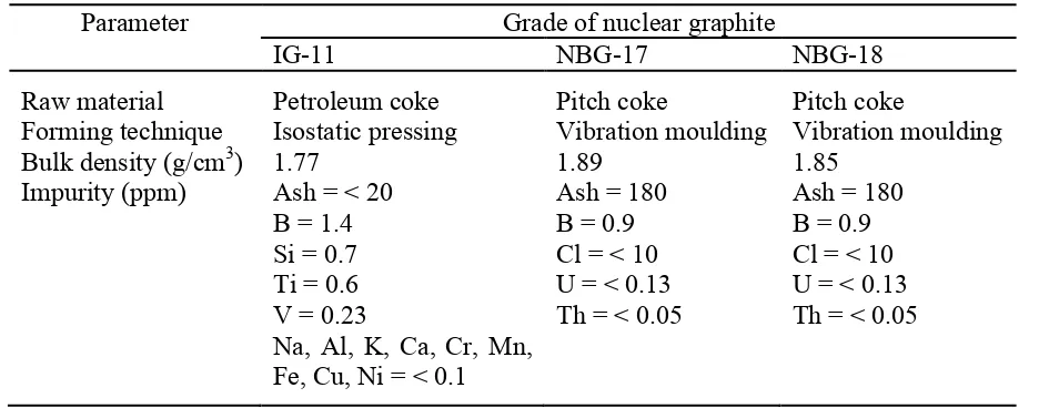
18 moulding or cold isostatic pressing. The amounts of petroleum coke and coal-tar pitch are usually about 70 wt % and 30 wt % respectively. The produced green articles are baked at ~1000°C (carbonisation) and impregnated with petroleum pitch several times (2-6) to increase strength and density of the bulk materials (Burchell 1999). The pre-treated bulk material is then graphitised at ~3000°C to form hexagonal graphite that closely matches the ideal hexagonal graphite structure. During graphitisation, chemical purification is carried out using cleaning agents (i.e. chlorine, fluorine, sodium fluoride, magnesium fluoride) and essentially heat treated in a halogen atmosphere. It is well known that halogen gases are capable of penetrating the pore structure of graphite, reacts with the impurities (neutron absorbing elements i.e. aluminium, boron, calcium, iron, silicon, vanadium, titanium) and vaporises as volatile halide salts. In the past (~1960), both chlorine and Freon gases were used to purify the graphite and in order to remove the residual chlorine from the graphite pore structures, the system was flushed with nitrogen or inert gas (Nightingale 1963). There is no clear information on any other gases used to flush the system, however the use of nitrogen is questionable as nitrogen will increase the production of 14C (see Section 2.4.4). It should be stressed that the residual impurities from the graphite and purification process also lead to the creation of problematic radionuclides. Due to the different raw materials, manufacturing and purification processes used, the properties of nuclear graphite are in general not similar as shown in Table 2-4; see also Table 2-5 for the chemical impurities detected in AGR and Magnox nuclear graphite.
Table 2-4: Characteristics of nuclear graphite (Lim et al 2008, Béghein et al 2012).
Parameter Grade of nuclear graphite
IG-11 NBG-17 NBG-18
Raw material Forming technique Bulk density (g/cm3) Impurity (ppm)
Petroleum coke Isostatic pressing 1.77
Ash = < 20 B = 1.4 Si = 0.7 Ti = 0.6 V = 0.23
Na, Al, K, Ca, Cr, Mn, Fe, Cu, Ni = < 0.1
Pitch coke
Vibration moulding 1.89
Ash = 180 B = 0.9 Cl = < 10 U = < 0.13 Th = < 0.05
Pitch coke
Vibration moulding 1.85
19 Table 2-5: Impurities detected in Magnox and AGR nuclear graphite (White et al 1984).
Element Magnox (ppm) AGR (ppm)
B N Na Mg Al Si S Cl Ca Ti V Cr Mn Fe Co Ni Zn Sr Mo Sn Ba W Pb
Li, Be, Ag, Cd, In, Sm, Eu, Gd, Dy, Bi
0.1 10 1.0 0.1 1.0 35 50 2.0 35 3 12 0.35 0.04 10 0.02 1.0 0.13 0.4 0.1 0.05 1.5 0.12 0.12 < 0.1 0.5 10 4.0 0.4 4.0 35 60 4.0 25 0.7 0.4 0.4 0.25 28 0.70 6.0 1.0 0.4 2.5 1.0 0.5 0.15 0.8 < 0.1
20 (naturally occurs in USA asphalt mine) as a filler material and formed by moulding technique. The coke prepared from Gilsonite produced spherical, onion-like grains, which had no preferential alignment to the forming process (Figure 2-5b). Thus the crystallites within the particles tended to align circumferentially leading to the production of bulk material with near isotropic behaviour.
Figure 2-5: Optical micrographs of nuclear grade graphite, (a) PGA graphite used in Magnox nuclear reactors, (b) GIL graphite used in AGR nuclear reactors (Hall et al 2006).
2.4.3. Waste Origin and Volume
As mentioned above nuclear graphite has been widely used in the past for the construction of various components in certain types of nuclear power reactors, for e.g. gas-cooled reactors and light water graphite reactors. The decommissioning and dismantling of these types of nuclear reactors consequently leads to irradiated graphite waste. This waste mostly originates from the moderator and reflector components as well as other minor applications such as fuel-channel sleeve, thermal column, fuel matrix and control rod materials (Nightingale 1963, IAEA 2006, 2010). At present, the huge volume of irradiated graphite waste has drawn significant attention and concern in all nuclear member countries. Approximately 260 000 tonnes of irradiated graphite waste requires an appropriate disposal decision and the volume identified in each waste producing country can be viewed in Figure 2-6. As can be seen in the pie chart, it is obvious that
21 the UK is the major contributor of irradiated graphite waste, followed by Russia, US, France and other minor contributors. This reflects the design of nuclear power reactors which utilise significant amounts of nuclear graphite. The main types of nuclear power reactors that are responsible for such volumes of irradiated graphite waste are as follows: UK – advanced gas-cooled reactor (AGR), magnesium alloy graphite moderated gas-gas-cooled uranium oxide reactor (Magnox), Russia – “reaktor bolshoy moshchnosti kanalniy” reactor (RBMK), US – high-temperature gas-cooled reactor (HTGR), light water graphite reactor (LWGR), France – “uranium naturel graphite gaz” reactor (UNGG).
Lithuana (1800) German (2000) Belgium (2500) Japan (3000) Italy (3000) South Korea (3500) Spain (3700) Ukraine (5700)
France (23000)
United Kingdom (96000) Russia
(60000)
[image:28.612.176.448.269.463.2]United States (55000)
Figure 2-6: Estimated volume of irradiated graphite (IAEA 2006, 2010, Fachinger 2012), numbers are in tonnes.
2.4.4. Radiation Effects on Graphite
22 used for different applications resulting in different irradiation behaviours (Burchell et al 1992, Goodwin et al 2014). To simplify, the effects of radiation on nuclear graphite are explained in rather general terms by considering the effect of fast and slow neutrons which may occur in all grades of nuclear graphite.
[image:29.612.195.420.464.654.2]Effects of fast neutrons – The use of nuclear graphite is purposely to reduce the kinetic energy of and/or reflect fast neutrons by elastic collisions. This elastic collision phenomenon results in structural alterations reducing the physical and mechanical properties of the original nuclear graphite (Kelly and Burchell 1994, Banhart 1999, Burchell and Snead 2007, Telling and Heggie 2007). For example, when a fast neutron (energetic particle) collides with an equilibrium graphite atom, the graphite atom will displace and create a cascade of displacements; a single neutron collides with multiple carbon atoms. The displaced carbon atoms recoil through the graphite lattice, displacing other carbon atoms and creating vacant lattice sites. Additionally, if the collisions happen in close proximity, clusters of point defects may occur (Telling and Heggie 2007). The displaced carbon atoms easily diffuse between the graphite layers and a proportion of these displaced carbon atoms will recombine immediately with the lattice vacancies (extremely dependent on the neutron flux and radiation temperature). This consequently creates a new graphite plane in so called dislocation loops or interstitial agglomerates (see Figure 2-7).
Figure 2-7: A dislocation loop between the graphitic nanoparticle basal planes (taken from Banhart 1999).
23 The interstitial clusters are less mobile than the vacancies and on further irradiation can be destroyed by fast neutron and/or carbon knock on atoms (irradiation annealing). The adjacent lattice vacancies in the same graphite layer may collapse towards the graphite layer and potentially form sinks for other vacancies, hence no longer able to recombine with and annihilate interstitials (Burchell 2012). It should be noted that this classical dislocation theory considers a simple situation that works on perfect parallel basal planes whereas in practice the graphite structure is far more complicated. As a result, more research needs to be carried out to understand the radiation damage in nuclear graphite i.e. taking account the displaced carbon atoms bridging to adjacent graphite planes and buckling as well as shearing effect of the graphite layers (Heggie et al 2011). Nevertheless, it has been shown that the displacement process altered the structure of original nuclear graphite leading to lower strength, making the graphite brittle with increased porosity and changed dimensions (swelling) and thus complicating the dismantling and handling during decommissioning process.
Another complicated phenomena occurring as a result of the displacement of carbon atoms by neutrons is the potential release of Wigner energy. Poor understanding of the effect of Wigner energy led to the Windscale pile 1 accident on 10th October 1957. Essentially, Wigner energy is the excess energy stored due to the presence of interstitial carbon atoms in non-ideal positions. This energy could be released when an interstitial carbon atom and a lattice vacancy recombine, or interplanar bonds are broken. The increase of stored Wigner energy only occurs with low temperature graphite radiation, < 250°C (IAEA 2000, 2006). This energy can be released violently as heat when the irradiated graphite is heated/annealed at 50°C above its initial irradiation temperature. Studies have demonstrated that the temperature rise during the release of Wigner energy could be as high as 1400°C (Rappeneau et al 1966). The effect of Wigner energy in nuclear reactors that are operated above 300°C is negligible as the stored energy is released slowly during operation (Burchell 2012). Due to the potential release of a huge amount of energy leading to a fire hazard, care must be taken when dealing with irradiated graphite that originated from low temperature (< 250°C) nuclear reactors.
24 present in both nuclear graphite and nuclear reactors. The main radioactive isotopes that usually are of concern in irradiated graphite are 3H, 14C and 36Cl (Brown et al 1999, IAEA 2004,
[image:31.612.79.535.239.452.2]Podruzhina 2004, Pichon et al 2008). The characteristic and activation reactions of these radioisotopes by impurities, which induce neutron capture cross-section are shown in Table 2-6.
Table 2-6: Characteristic and activation reactions of 3H, 14C and 36Cl. Thermal neutron cross section data (Mughabghab et al 1981, Haynes 2014).
Radionuclide
(half-life) Activation reaction Origin (natural abundance %)
Thermal neutron cross section (barn)
3H (12.3 years) 235U(n,f)3H 6Li(n,α)3H 3He(n,p)3H 10B(n,2α)3H
Fission reaction of fuel (0.7204) Li impurity in graphite (7.59) He coolant (0.000134) Control rod (19.9)
586 940 5330 3840
14C (5670 years) 14N(n,p)14C 13C(n,γ)14C 17O(n,α)14C
Air in graphite (99.636) Graphite, coolant, fuel (1.07)
Air in graphite, coolant, fuel (0.038) 1.93 0.0014 0.257
36Cl (308000 years) 35Cl(n,γ)36Cl Cl impurity in graphite – purification
process (75.76)
43.7
Other minor contamination from graphite impurities, nuclear reactor components (impurities in coolant, metallic elements) and fission products may also be present in irradiated graphite, e.g.
60Co, 55Fe, 63Ni (IAEA 2010). However this is very dependent on the origin of the nuclear
178
References
Abdelouas A, Noirault S and Grambow B 2006 Immobilization of inert TRISO coated fuel in glass for geological disposal J. Nucl. Mater. 358 1–9
Abid M, Et-tabirou M and Taibi M 2003 Structure and DC conductivity of lead sodium ultraphosphate glasses Mater. Sci. Eng. B 97 20–4
Adamantiades A and Kessides I 2009 Nuclear power for sustainable development: current status and future prospects Energy Policy 37 5149–66
Almeida F J M, Martinelli J R and Partiti C S M 2007 Characterization of iron phosphate glasses prepared by microwave heating J. Non. Cryst. Solids 353 4783–91
Amjad Z and Zuhl R 2006 Kinetic and morphological investigation on the precipitation of calcium carbonate in the presence of inhibitors Corrosion NACExpo 2006, 61st annual conference & exposition p 6385
Andreev G E 1991 A review of the Brazilian test for rock tensile strength determination. Part I: calculation formula Min. Sci. Technol. 13 445–56
Banhart F 1999 Irradiation effects in carbon nanostructures Reports Prog. Phys. 62 1181–221 Barclay J and Carroll M 1996 Pre-eruptive volatile content and degassing history of an evolving
peralkaline volcano J. Volcanol. Geotherm. Res. 74 75–87
Bayliss S, Ewart F T, Howse R M, Dmith-Briggs J L, Thomason H P and Wilmott H A 1987 The solubility and sorption of lead-210 and carbon-14 in a near-field environment Scientific Basis for Nuclear Waste Management XI, MRS Proceedings vol 112 pp 33–42
Beckman Coulter Inc. 2011 Coulter LS series, product manual TECDOC PN 4237214EA 4–3 Béghein P, Berlioux G, Mesnildot B Du, Hiltmann F and Melin M 2012 NBG-17 - An improved
graphite grade for HTRs and VHTRs Nucl. Eng. Des. 251 146–9
Bingham P A, Hand R J and Forder S D 2006 Doping of iron phosphate glasses with Al2O3, SiO2
or B2O3 for improved thermal stability Mater. Res. Bull. 41 1622–30
Bingham P A, Hand R J, Forder S D and Lavaysierre A 2005 Vitrified metal finishing wastes: II. Thermal and structural characterisation J. Hazard. Mater. 122 129–38
179 Bingham P A, Hyatt N C and Hand R J 2012 Vitrification of UK intermediate level radioactive wastes arising from site decommissioning: property modelling and selection of candidate host glass compositions Glas. Technol. Eur. J. Glas. Sci. Technol. A 53 83–100
Bingham P a. and Jackson C M 2008 Roman blue-green bottle glass: chemical-optical analysis and high temperature viscosity modelling J. Archaeol. Sci. 35 302–9
Birkel C S, Douglas J E, Lettiere B R, Seward G, Zhang Y, Pollock T M, Seshadri R and Stucky G D 2013 Influence of Ni nanoparticle addition and spark plasma sintering on the TiNiSn– Ni system: Structure, microstructure, and thermoelectric properties Solid State Sci. 26 16– 22
Bootjomchai C, Laopaiboon J, Nontachat S, Tipparach U and Laopaiboon R 2012 Structural investigation of borosilicate recycled-barium – bismuth glasses under the influence of gamma-irradiation through ultrasonic and FTIR studies Nucl. Eng. Des. 248 28–34
Brown F J, Palmer J D and Wood P 1999 Derivation of a radionuclide inventory for irradiated graphite-chlorine-36 Inventory determination Proc. IAEA Tech. Comm. Meet. 143–52 Burchell T D 1999 Carbon materiales for advanced technologies (Pergamon: Elsevier Science
Ltd., Oxford)
Burchell T D 2012 Comprehensive nuclear materials: radiation effects in graphite vol 4, ed R J M Konings (Elsevier Science Ltd., Oxford)
Burchell T D, Eatherly W P, Robbins J M and Strizak J P 1992 The effect of neutron irradiation on the structure and properties of carbon-carbon composite materials J. Nucl. Mater. 191-194 295–9
Burchell T D and Snead L L 2007 The effect of neutron irradiation damage on the properties of grade NBG-10 graphite J. Nucl. Mater. 371 18–27
Cassingham N J, Bingham P A, Hand R J and Forder S D 2008 Property modification of a high level nuclear waste borosilicate glass through the addition of Fe2O3 Glas. Technol. 49 21–6
Chadwick J 1932 The existence of a neutron Proc. R. Soc. A Math. Phys. Eng. Sci. 136 692–708 Chakraborty S and Arora A K 2012 Temperature evolution of Raman spectrum of iron phosphate
glass Vib. Spectrosc. 61 99–104
Chen Q, Tang C Y, Chan K C and Liu L 2013a Viscous flow during spark plasma sintering of Ti-based metallic glassy powders J. Alloys Compd. 557 98–101
180 Choi E-Y, Han T H, Hong J, Kim J E, Lee S H, Kim H W and Kim S O 2010 Noncovalent functionalization of graphene with end-functional polymers J. Mater. Chem. 20 1907–12 Online: See Supplementary Info
Cochran T B, Feiveson H A, Patterson W, Pshakin G, Ramana M V, Schneider M, Suzuki T and Hippel F V 2010 Fast Breeder Reactor Programs: History and Status vol 8 (International Panel on Fissile Materials)
Córdoba J M, Chicardi E, Poyato R, Gotor F J, Medri V, Guicciardi S and Melandri C 2013 Spark plasma sintering of TixTa1−xC0.5N0.5-based cermets: Effects of processing conditions
on chemistry, microstructure and mechanical properties Chem. Eng. J. 230 558–66
CoRWM 2006 Managing our radioactive waste safely: CoRWM’s recommendations to government CoRWM Doc 700
Darwish H and Gomaa M M 2006 Effect of compositional changes on the structure and properties of alkali-alumino borosilicate glasses J. Mater. Sci. Mater. Electron. 17 35–42 Day D E, Wu Z, Ray C S and Hrma P 1998 Chemically durable iron phosphate glass wasteforms
J. Non. Cryst. Solids 241 1–12
DECC 2013 Consultation review of the siting process for a geological disposal facility URN 13D/250
DECC 2014 Implementing geological disposal: a framework for the long-term management of higher activity radioactive waste URN 14D/235
Defra, BERR and the devolved administrations for Wales and Northen Ireland 2008 Managing radioactive waste safely: a framework for implementing geological disposal Cm 7386 Defra, DTI and Administrations D 2007 Policy for the long term management of solid low level
radioactive waste in the United Kingdom PB 12522
Dickson D P E and Berry F J 1986 Mossbauer spectroscopy (Cambridge University Press) Djohari H and Derby J J 2009 Transport mechanisms and densification during sintering: II.
Grain boundaries Chem. Eng. Sci. 64 3810–6
Djohari H, Martínez-Herrera J I and Derby J J 2009 Transport mechanisms and densification during sintering: I. Viscous flow versus vacancy diffusion Chem. Eng. Sci. 64 3799–809 Donald I W 2010 Waste immobilization in glass and ceramic based hosts: radioactive, toxic and
hazardous wastes (John Wiley & Sons Ltd, West Sussex)
181 Dubourg M 1998 Technologies fro gas cooled reactor decommissioning, fuel storage and waste
disposal: the carbon 14 Cycle IAEA TECDOC 1043 233–7
Duderstadt J J and Hamilton L J 1976 Nuclear reactor analysis (John Wiley and Sons, Inc., New York)
Dunbar N W and Kyle P R 1992 Volatile contents of obsidian clasts in tephra from the Taupo Volcanic Zone, New Zealand: Implications to eruptive processes J. Volcanol. Geotherm. Res. 49 127–45
Dunzik-Gougar M Lou and Smith T E 2014 Removal of carbon-14 from irradiated graphite J. Nucl. Mater. 451 328–35
Dyar M D, Agresti D G, Schaefer M W, Grant C A and Sklute E C 2006 Mössbauer spectroscopy of earth and planetary materials Annu. Rev. Earth Planet. Sci. 34 83–125 Einstein A 1905 Does the inertia of a body depend upon its energy-content? (Ist die Trägheit
eines Körpers von seinem Energieinhalt abhängig?) Ann. Phys. 1–3
Elbouaanani L K, Malaman B and Gérardin R 1999 Structure refinement and magnetic properties of C–Fe(PO3)3 studied by neutron diffraction and Mössbauer techniques J. Solid
State Chem. 148 455–63
El-Egili K 2003 Infrared studies of Na2O – B2O3 – SiO2 and Al2O3 – Na2O – B2O3 – SiO2 glasses
Phys. B 325 340–8
Ericson J E, Makishima A, Mackenzie J D and Berger R 1975 Chemical and physical properties of obsidian: a naturally occuring glass J. Non. Cryst. Solids 17 129–42
Ericsson T, Nord A G, Ahmed M M O, Gismelseed A and Khangi F 1990 Fe2P2O7 and Fe2P4O12
studied between 5–800 K Hyperfine Interact. 57 2179–86
Fachinger J 2012 Comprehensive nuclear materials: Graphite vol 5, ed R J M Konings (Elsevier Science Ltd., Oxford)
Fachinger J, Grosse K H, Hrovat M and Seemann R 2012 Utilization of HTR reflector graphite as embedding matrix for radioactive waste Nucl. Eng. Des. 251 235–8
Fachinger J, von Lensa W and Podruhzina T 2008 Decontamination of nuclear graphite Nucl. Eng. Des. 238 3086–91
Forder S D, Bingham P A, McGann O J, Stennett M C and Hyatt N C 2012 Mössbauer studies of materials used to immobilise industrial wastes Hyperfine Interact. 217 83–90
182 Frenkel J 1945 Viscous flow of crystalline bodies under the action of surface tension J. Phys.
USSR 9 385–91
Frisch O R 1939 Physical evidence for the division of heavy nuclei under neutron bombardment Nature 143 276–276
Furukawa T, Fox K E and White W B 1981 Raman spectroscopic investigation of the structure of silicate glasses. III. Raman intensities and structural units in sodium silicate glasses J. Chem. Phys. 75 3226
Gaafar M S and Marzouk S Y 2007 Mechanical and structural studies on sodium borosilicate glasses doped with Er2O3 using ultrasonic velocity and FTIR spectroscopy Phys. B 388
294–302
Galeener F L 1982 Planar rings in glasses Solid State Commun. 44 1037–40
Garcia-lodeiro I, Fernández-jimenez A, Pena P and Palomo A 2014 Alkaline activation of synthetic aluminosilicate glass Ceram. Int. 40 5547–58
Girke N A, Bushuev A V, Kozhin A F, Petrova E V, Aleeva T B and Zubarev V N 2012 14C in
spent graphite from uranium-graphite reactors at the Siberian chemical combine At. Energy 112 63–6
Goodhew P J, Humphreys F J and Beanland R 2001 Electron microscopy and analysis (Taylor & Francis, London)
Goodwin C, Barkatt A and Al-Sheikhly M 2014 On the mechanism of the interactions of neutrons and gamma radiation with nuclear graphite-implications to HTGRs Radiat. Phys. Chem. 97 38–47
Greenwood N N and Earnshaw A 1997 Chemistry of the elements (Butterworth-Heinemann, Oxford)
Guillon O, Gonzalez-Julian J, Dargatz B, Kessel T, Schierning G, Räthel J and Herrmann M 2014 Field-assisted sintering technology/spark plasma sintering: mechanisms, materials, and technology developments Adv. Eng. Mater. 16 830–49
Guiroy J J 1995 Graphite waste incineration in a fluidized bed Spec. Meet. Graph. moderator lifecycle Behav. 193–203
Guyon J, Hazotte A, Monchoux J P and Bouzy E 2013 Effect of powder state on spark plasma sintering of TiAl alloys Intermetallics 34 94–100
Hafid M, Jermoumi T, Toreis N and Ghailassi T 2002 Structure of (45−x)Na2O–xBaO–5ZnO–
183 Hall G, Marsden B J and Fok S L 2006 The microstructural modelling of nuclear grade graphite
J. Nucl. Mater. 353 12–8
Haynes W M 2014 CRC handbook of chemistry and physics, 95th edition, 2014-2015 (CRC Press/Taylor and Francis, Boca Raton, FL)
Heath P G, Corkhill C L, Stennett M C, Hand R J, Meyer W C H M and Hyatt N C 2013 Encapsulation of TRISO particle fuel in durable soda-lime-silicate glasses J. Nucl. Mater. 436 139–49
Heggie M I, Suarez-Martinez I, Davidson C and Haffenden G 2011 Buckle, ruck and tuck: a proposed new model for the response of graphite to neutron irradiation J. Nucl. Mater. 413 150–5
Her Majesty’s Stationery Office 1995 Review of radioactive waste management policy: final conclusions Cm 2919
Hietanfn R, Jaakkola T and Miettinen J K 1984 Sorption of cesium, strontiuli, iodine and carbon in concrete and sand Scientific Basis for Nuclear Waste Management VIII, MRS Proceedings vol 44 pp 891–8
Hisa M, Tsutsumi A and Akiyama T 2004 Reduction of iron oxides by nano-sized graphite particles observed in pre-oxidized iron carbide at temperatures around 873 K Mater. Trans. 45 1907–10
Hrovat M, Grosse K-H and Seemann R 2013 Matrix material comprising graphite and an inorganic binder suited for final disposal of radioactive waste, a process for producing the same and its processing and use US Patent, US 8502009 B2
Huang C and Behrman E C 1991 Structure and properties of calcium aluminosilicate glasses J. Non. Cryst. Solids 128 310–21
Huang S, Swarnakar A K, Vanmeensel K and Vleugels J 2013 Diamond dispersed Si3N4 composites obtained by pulsed electric current sintering J. Eur. Ceram. Soc. 33 1237–47 Huang W, Day D E, Ray C S, Kim C-W and Mogus-Milankovic A 2004 Vitrification of high
chrome oxide nuclear waste in iron phosphate glasses J. Nucl. Mater. 327 46–57
Huang W-H, Tsai S-C, Yang C-W and Kai J-J 2014 The relationship between microstructure and oxidation effects of selected IG- and NBG-grade nuclear graphites J. Nucl. Mater. 454 149– 58
Hussainova I, Voltšihhin N, Cura E and Hannula S-P 2014 Densification and characterization of spark plasma sintered ZrC–ZrO2 composites Mater. Sci. Eng. A 597 75–81
184 IAEA 2006 Characterization, treatment and conditioning of radioactive graphite from
decommissioning of nuclear reactors TECDOC 1521
IAEA 2011 Disposal of radioactive waste: specific safety requirements No. SSR-5
IAEA 2014a Energy, electricity and nuclear power estimates for the period up to 2050 Ref. Data Ser. No. 1, 2014 Ed.
IAEA 2000 Irradiation damage in graphite due to fast neutrons in fission and fusion systems TECDOC 1154
IAEA 2004 Management of waste containing tritium and carbon-14 Tech. Reports Ser. No. 421 IAEA 2007 Nuclear power plant design charateristics: structure of nuclear power plant design
characteristics in the IAEA power reactor information system (PRIS) TECDOC 1544 IAEA 2014b Nuclear power reactor in the world Ref. Data Ser. No. 2, 2014 Ed.
IAEA 2010 Progress in radioactive graphite waste management TECDOC 1647 IEA 2014a Key world energy statistics Inernational Energy Agency
IEA 2014b World energy outlook Inernational Energy Agency
IUPAC 1997 Compendium of chemical terminology (the “gold book”) ed A D McNaught, A Wilkinson and A Jenkins (Blackwell Scientific Publications, Oxford)
Jermoumi T, Hafid M, Niegisch N, Mennig M, Sabir A and Toreis N 2002 Properties of (0.5−x)Zn–xFe2O3–0.5P2O5 glasses Mater. Res. Bull. 37 49–57
Joseph K, Premila M, Amarendra G, Govindan Kutty K V, Sundar C S and Vasudeva Rao P R 2012 Structure of cesium loaded iron phosphate glasses: an infrared and Raman spectroscopy study J. Nucl. Mater. 420 49–53
Kalampounias A G 2011 IR and Raman spectroscopic studies of sol–gel derived alkaline-earth Bull. Mater. Sci. 34 299–303
Kamitsos E 1996 Reply to “Comment on Infrared-reflectance spectra of heat-treated, sol-gel-derived silica” Phys. Rev. B 53 14659–62
Kamitsos E I, Kapoutsis J A, Jain H and Hsieh C H 1994 Vibrational study of the role of trivalent ions in sodium trisilicate glass J. Non. Cryst. Solids 171 31–45
185 Karabulut M, Metwalli E, Day D E and Brow R K 2003 Mössbauer and IR investigations of iron
ultraphosphate glasses J. Non. Cryst. Solids 328 199–206
Karlina O K, Klimov V L, Ojovan M I, Pavlova G Y, Dmitriev S A and Yurchenko A Y 2005 Immobilization of carbon-14 from reactor graphite waste by use of self-sustaining reaction in the C–Al–TiO2 system J. Nucl. Mater. 345 84–5
Kelly B T 1981 Physics of graphite (Applied Science Publishers, London)
Kelly B T and Burchell T D 1994 Structure-related property changes in polycrystalline graphite under neutron irradiation Carbon N. Y. 32 499–505
Kharissova O V., Kharisov B I and Valdés J J R 2010 Review: the use of microwave irradiation in the processing of glasses and their composites Ind. Eng. Chem. Res. 49 1457–66
Kim C-W and Day D E 2003 Immobilization of Hanford LAW in iron phosphate glasses J. Non. Cryst. Solids 331 20–31
Kim T, Lee J and Lee K-H 2014 Microwave heating of carbon-based solid materials Carbon Lett. 15 15–24
Kjeldsen J, Smedskjaer M M, Mauro J C, Youngman R E, Huang L and Yue Y 2013 Mixed alkaline earth effect in sodium aluminosilicate glasses J. Non. Cryst. Solids 369 61–8
Lai Y, Liang X, Yang S, Liu P, Zeng Y and Hu C 2014 Raman and FTIR spectra of CeO2 and
Gd2O3 in iron phosphate glasses J. Alloys Compd. 617 597–601
Lai Y, Liang X, Yin G, Yang S, Wang J, Zhu H and Yu H 2011a Infrared spectra of iron phosphate glasses with gadolinium oxide J. Mol. Struct. 1004 188–92
Lai Y M, Liang X F, Yang S Y, Wang J X, Cao L H and Dai B 2011b Raman and FTIR spectra of iron phosphate glasses containing cerium J. Mol. Struct. 992 84–8
Larkin P J 2011 “IR and Raman spectroscopy - principles and spectral interpretation” (Elsevier, USA)
Lee W E, Ojovan M I and Jantzen C M 2013 Radioactive waste management and contaminated site clean-Up (Woodhead Publishing Limited, Cambridge)
Lewis E E 2008 Fundamentals of nuclear reactor physics (Academic Press/Elsevier, Burlington, MA)
186 Lipińska M E, Novais J P, Rebelo S L H, Bachiller-Baeza B, Rodríguez-Ramos I, Guerrero-Ruiz A and Freire C 2014 Microwave-assisted silylation of graphite oxide and iron(III) porphyrin intercalation Polyhedron 81 475–84
Lowenstern J B, Bleick H, Vazquez J a., Castro J M and Larson P B 2012 Degassing of Cl, F, Li, and Be during extrusion and crystallization of the rhyolite dome at Volcán Chaitén, Chile during 2008 and 2009 Bull. Volcanol. 74 2303–19
Ma L, Brow R K and Choudhury A 2014 Structural study of Na2O–FeO–Fe2O3–P2O5 glasses by
Raman and Mössbauer spectroscopy J. Non. Cryst. Solids 402 64–73
MacDonald S A, Schardt C R, Masiello D J and Simmons J H 2000 Dispersion analysis of FTIR reflection measurements in silicate glasses J. Non. Cryst. Solids 275 72–82
Mackenzie J K and Shuttleworth R 1949 A phenomenological theory of sintering Proc. Phys. Soc. Sect. B 62 833–52
Magnox and NDA 2013 Intermediate level waste (ILW) storage and fuel element debris (FED) treatment optimisation study Online: http://www.nda.gov.uk/publication/intermediate-level-waste-ilw-storage-and-fuel-element-debris-fed-treatment-optimisation-study/
Mahdy E A and Ibrahim S 2012 Influence of Y2O3 on the structure and properties of calcium
magnesium aluminosilicate glasses J. Mol. Struct. 1027 81–6
Marasinghe G K, Karabulut M, Ray C S, Day D E, Shuh D K, Allen P O, Saboungi M L, Grimsditch M and Haeffner D 2000 Properties and structure of vitrified iron phosphate nuclear wasteforms J. Non. Cryst. Solids 263 146–54
Márquez E, Piña G, Rodriguez M, Fachinger J, Grosse K, Luis J, Nieto L, Gracian M Q and Seemann R 2011 GRAFEC: a new spanish program to investigate waste management options for radioactive graphite WM2012 Conference, February 26 – March 1, 2011, Phoenix, Arizona, USA
Marzouk S Y, Seoudi R, Said D A and Mabrouk M S 2013 Linear and non-linear optics and FTIR characteristics of borosilicate glasses doped with gadolinium ions Opt. Mater. (Amst). 35 2077–84
Mazo M A, Palencia C, Nistal A, Rubio F, Rubio J and Oteo J L 2012 Dense bulk silicon oxycarbide glasses obtained by spark plasma sintering J. Eur. Ceram. Soc. 32 3369–78 Mazurin O V. 2007 Problems of compatibility of the values of glass transition temperatures
published in the world literature Glas. Phys. Chem. 33 22–36
187 McGann O J, Bingham P A, Hand R J, Gandy A S, Kavčič M, Žitnik M, Bučar K, Edge R and Hyatt N C 2012 The effects of γ-radiation on model vitreous wasteforms intended for the disposal of intermediate and high level radioactive wastes in the United Kingdom J. Nucl. Mater. 429 353–67
McGann O J and Ojovan M I 2011 The synthesis of graphite–glass composites intended for the immobilisation of waste irradiated graphite J. Nucl. Mater. 413 47–52
Mcgill S L, Walkiewicz W E and Clark A E 1995 Microwave heating of chemicals and minerals Rep. Investig. 9518
McKeown D A, Buechele A C, Viragh C and Pegg I L 2010 Raman and X-ray absorption spectroscopic studies of hydrothermally altered alkali-borosilicate nuclear waste glass J. Nucl. Mater. 399 13–25
McMillan P 1984 Structural studies of silicate glasses and melts-applications and limitations of Raman spectroscopy Am. Mineral. 69 622–44
McMillan P and Piriou B 1982 The structures and vibrational spectra of crystals and glasses in the silica-alumina system J. Non. Cryst. Solids 53 279–98
Mcmillan P, Piriou B and Navrotsky A 1982 A Raman spectroscopic study of glasses along the joins silica-calcium aluminate, silica-sodium aluminate, and silica-potassium aluminate Geochim. Cosmochim. Acta
Meitner L and Frisch O R 1939 Breaking up is easy - nuclear fission discovered Nature 143 239–40
Menéndez J a., Arenillas A, Fidalgo B, Fernández Y, Zubizarreta L, Calvo E G and Bermúdez J M 2010 Microwave heating processes involving carbon materials Fuel Process. Technol. 91 1–8
Menyah K and Wolde-Rufael Y 2010 CO2 emissions, nuclear energy, renewable energy and
economic growth in the US Energy Policy 38 2911–5
Mercier M, Di Muro A, Giordano D, Métrich N, Lesne P, Pichavant M, Scaillet B, Clocchiatti R and Montagnac G 2009 Influence of glass polymerisation and oxidation on micro-Raman water analysis in alumino-silicate glasses Geochim. Cosmochim. Acta 73 197–217
Meredith R J 1998 Engineers’ handbook of industrial microwave heating (The Institution of Electrical Engineers, London)
188 Moguš-Milanković A, Šantić A, Reis S T, Furić K and Day D E 2004 Mixed ion–polaron
transport in Na2O–PbO–Fe2O3–P2O5 glasses J. Non. Cryst. Solids 342 97–109
Mondal K, Lorethova H, Hippo E, Wiltowski T and Lalvani S B 2004 Reduction of iron oxide in carbon monoxide atmosphere-reaction controlled kinetics Fuel Process. Technol. 86 33–47 Morgan L E, Renne P R, Taylor R E and WoldeGabriel G 2009 Archaeological age constraints
from extrusion ages of obsidian: examples from the middle Awash, Ethiopia Quat. Geochronol. 4 193–203
Mughabghab S F, Divadeenam M, Holden N E, Kinsey R R and McLane V 1981 Neutron cross section series ed S F Mughabghab, R R Kinsey and C L Dunford (Academic Press Inc. (London) Ltd.)
Mysen B O 1990 Interaction between water and melt in the system CaAl2O4-SiO2-H2O Chem.
Geol. 88 223–43
Mysen B O, Virgo D and Seifert F A 1982 The stucture of silicate melts: implications for chemical and physical properties of natural magma Rev. Geophys. Sp. Phys. 20 353–83 Nakahara M and Sanada Y 1995 FT-IR ATR spectroscopy of the edge surface of pyrolytic
graphite and its surface/PVC interface J. Mater. Sci. 30 4363–8
NDA 2011 UK Management of solid low level radioactive waste from the nuclear industry: low level waste strategic review NLWS/LLWR/16
NDA 2009 UK radioactive higher activity waste storage review UK radioactive higher activity waste storage review Online: http://www.nda.gov.uk/publication/uk-radioactive-higher-activity-waste-storage-review-march-2009/
NDA 2010 UK strategy for the management of solid low level radioactive waste from the nuclear industry Online: http://www.nda.gov.uk/publication/uk-strategy-for-the-management-of-solid-low-level-radioactive-waste-from-the-nuclear-industry-august-2010/ NDA and DECC 2013 Radioactive wastes in the UK: a summary of the 2013 inventory Online:
https://www.nda.gov.uk/wp-content/uploads/sites/2/2014/02/14D039-NDASTSTY140006-UKRWI-2013-High-Level-Summary.pdf
Neuville D, Cormier L and Massiot D 2006 Al coordination and speciation in calcium aluminosilicate glasses: Effects of composition determined by 27Al MQ-MAS NMR and Raman spectroscopy Chem. Geol. 229 173–85