http://dx.doi.org/10.4236/jsea.2014.72012
Software Composition Using Behavioral Models of Design
Patterns
Sargon Hasso
1, Carl Robert Carlson
21
Technical Product Development, Wolters Kluwer Law and Business, Chicago, USA; 2Information Technology and Management, Illinois Institute of Technology, Wheaton, USA.
Email: [email protected]
Received January 1st, 2014; revised January 30th, 2014; accepted February 7th, 2014
Copyright © 2014 Sargon Hasso, Carl Robert Carlson. This is an open access article distributed under the Creative Commons Attri-bution License, which permits unrestricted use, distriAttri-bution, and reproduction in any medium, provided the original work is properly cited. In accordance of the Creative Commons Attribution License all Copyrights © 2014 are reserved for SCIRP and the owner of the intellectual property Sargon Hasso, Carl Robert Carlson. All Copyright © 2014 are guarded by law and by SCIRP as a guardian.
ABSTRACT
Given a set of requirements structured as design problems, we can apply design patterns to solve each problem individually. Much of the published literature on design patterns addresses this problem—pattern association; however, there is no systematic and practical way that shows how to integrate those individual solutions together. We propose a compositional model based on design patterns by abstracting their behavioral model using role modeling constructs. This approach describes how to transform a design pattern into a role model that can be used to assemble a software application. The role model captures the behavioral relationship between participant components in the design pattern. Our approach offers a complete practical design and implementation strate-gies, adapted from DCI (Data, Context, and Interaction) architecture. We demonstrate our technique by pre-senting a simple case study complete with design and implementation code. We also present a simple to follow process that provides guidelines of what to do and how to do it.
KEYWORDS
Software Composition; Design Patterns; Integration; Role Model; Architecture; DCI Architecture; System Responsibilities; Traits
1. Introduction
In our prior research [1], we laid out the foundational theory for constructing system architecture by composing components using design patterns [2] as solutions to in-tegration problems. The use of patterns as inin-tegration mechanism is different from using them, as originally conceived, as solutions to design problems. Integration based on design patterns, as we will show later, is be-havioral in nature, i.e. based on collaboration, and is se-mantically richer than the traditional structural-based ap-proach using generalization, aggregation, and association. The literature abounds with techniques to help designers practice and apply design patterns in building applica-tions; however, very little attention is paid to how to as-semble applications in a systematic way from pattern- based components.
In examining how the Lexi editor case study was
as-sembled in Gamma etal. [2] book, or how the hierarchi-cal file system (HFS) case study was assembled in Vlis-sides [3] book, it is not very obvious how the final appli-cation is assembled from components without explaining the assembly, or composition, process explicitly. From our teaching experience to students who are assigned design projects to build applications using design pat-terns, similar to Lexi and HFS, we found out that they struggle with integrating components together. This prob-lem motivated us to research this probprob-lem and come up with an approach to integrate components using design patterns themselves as an abstraction mechanism and transforming those abstractions into realization during implementation. To emphasize, we are introducing de-sign patterns as abstract modeling elements to solve con-crete software composition problems.
niques for software composition. In Section 3, we lay out the conceptual background needed to use our approach. In Section 4, we describe just enough concepts from DCI architecture we need for our implementation strategy. To provide support in following our proposed approach, we present in Section 5 a simple to follow process that pro-vides guidelines of what to do and how to do it. A simple case study is introduced in Section 6 demonstrating our approach during design and implementation. A brief discussion is given in Section 7, then our conclusion and future work are discussed in Section 8. To make the con- cepts concrete, we also provide a complete source code listing of the case study in Appendix.
2. Related Work
Decomposing an application into design problems and finding solutions based on design patterns creates an in-tegration problem designers must deal with. This is also true even though design solutions are not patterns-based. Bass etal. [4] talk about one of the desired system qual-ity attributes a software architecture should have, namely integrability which they define as: “the ease with which separately developed components, including those de-veloped by third parties, can be made to work together to fulfill the software’s requirements”. Currently, there are no systematic approaches to integrate patterns-based components. Case studies found in Gamma etal. [2], and Vlissides [3] use ad hoc approaches to do integration. Moreover, the integration tends to be untraceable, unme-thodical, order-dependent, and non-repeatable. It does rely heavily on the experience of designers to come up with integration strategies.
An approach by Yacoub etal. [5] uses design patterns for composition and those patterns are referred to as con-structionaldesignpatterns. Basically these are design pat-terns plus an interface specification. Gluing patpat-terns to-gether is accomplished by two types of interfaces: classes and operations. In other words, two patterns can be inte-grated using either a sharedobject or an operation. The selection of either interfaces is arbitrary. The chosen ob-ject or operation comes from existing model elements in design patterns. The biggest disadvantage of this approach is the fact that you must, somehow, identify parts, either objects or operations, of the two patterns to be used as interfaces. If one pattern-based component requires an operation that a participating object from another pat-tern-based component does not have, this approach may not work.
Riehle [6] describes an approach for composing design patterns-based components using the roles concept. This approach still relies on roles’ relationship similar to class’ relationship. This is an unnecessary constraint during analysis phase. Furthermore, his composition technique
constrains pattern integration to produce composite de- signs that are patterns themselves which limits the wide applicability of this approach.
Our approach offers a complete design and implemen- tation strategies with a set of techniques that most soft- ware engineers are familiar with. Contrast this approach with the formal approaches we surveyed in the literature that are difficult to comprehend and implement unless proper software tools are available. For example, the me- thod in [7] starts with the explicit design pattern model structure as a basis for composing patterns by specifying their structural and behavioral properties using two types of logics: first-order logic [8] and temporal logic of ac- tions [9], respectively. The resulting specifications are incomprehensible to most practitioners unfamiliar with formal methods of specifying designs.
3. Theory: Conceptual Foundation
Design patterns are commonly used as techniques that offer solutions to commonly recurring problems when building software components or applications [2]. How- ever, we have come up with a compositionalmodel based on design patterns by abstracting their behavioralmodel
using rolemodelingconstructs. What we mean by com- positional model is similar to what we do when we as- semble a software component from, say, two objects through typical software composition techniques like gen- eralization, aggregation, and association. Shared object is another technique used for this purpose [2]. However, the compositional model exhibited by these techniques is structural. Naturally, this structure results when system functionality is decomposed into modules arranged into any number of possible arrangements. Our compositional model, on the other hand, is behavioral in nature because it is based on the collaboration model derived from de- sign patterns that has specific semantics based on the design pattern we use. In order to describe this collabora- tion model, as we will illustrate shortly, we have to spec- ify the design patterns as role models. Each design pat- tern we choose will have a different role model. How do we obtain these role models? For each design pattern, we examine its participants’ collaboration behavior, and factor out their responsibilities. A responsibility is col- lection of behaviors, or functions, or tasks, or services. We then specify the resulting role model much like a
integration process. It is very important to realize that in addition to using design patterns to solve a design prob- lem, we are also proposing using design patterns to solve an integration problem. The fact that a design pattern has a collaboration context with participants with prescribed behavior is what we are abstracting.
In role modeling, each distinct system activity or a behavior, a use case for example, is considered and mod- eled individually. We generally examine the roles of two or more interacting entities during behavior analysis. The same entities may assume different roles in yet other in- teraction scenarios describing a different aspect of sys- tem behavior. In general, one system functionality may span several objects belonging to different classes (this is the same as saying that several objects, in their different roles, are collaborating to execute a function). Another system functionality may span the same or additional objects. However, this time the same objects may take on a different role. To describe a complete behavior of one specific object, the different roles are composed or syn- thesized. This resultant synthesized behavior is assem- bled and implemented as a class. It is highly likely that this role modeling is happening implicitly in the software designer’s mind but the thought process can be made explicit and there are several approaches in the literature dealing with this problem.
Role diagrams that depict the role model is appropriate at this level of analysis because they involve the collabo- ration of two or more objects. This also provides the con- text to model the structure of object interaction [12]. This idea does not seem to be different from the way design patterns are defined: “... design pattern identifies the par- ticipating classes and instances, their roles and collabora- tions, and their distribution of responsibilities ...” [2].
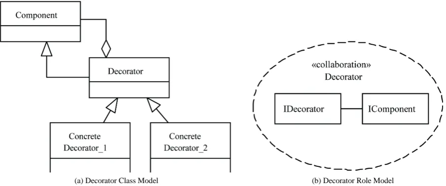
Role modeling in this discussion, therefore, is used in two different ways: first, as a way to expose different
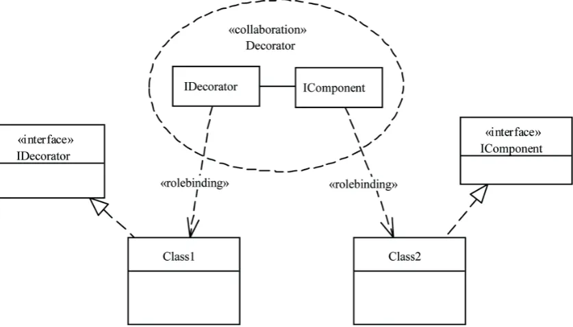
[image:3.595.73.526.530.719.2]interfaces by the same object, depending how it interacts with other objects, and second, as a way to describe col- laboration between two or more objects during an enact- ment of, say, one system functionality or one use case scenario. The former is what traits [13] were used for, something we are not interested in here; while the latter is what we will be utilizing to model system behavior that is factorable. We will utilize the concept of a role as a partial description of an object’s specifications during collaboration with other objects. Henceforth, when dis- cussing design pattern components (participants), we will refer to them as illustrated in Figure 1(b). Essentially, this means the design pattern, in this case the Decorator [2] (p. 175), see Figure 1(a), has two components represented by two roles: Decorator and Component. It’s these two roles that really get mapped or injected into objects when doing design integration using design pat- terns. As the diagram in Figure 1(b) shows, we use the UML’s [10] collaboration as a dashed ellipse icon which represents the design pattern we are using as an integra- tor. In the collaborations model, we capture how a col- lection of communicating objects collectively accompli- shes a specific task. We achieve composition by the vir- tue of how participants in the chosen design pattern com- municate. The parts in each collaboration composite stru- cture represent the roles that we factored out from each design pattern as an abstraction that ultimately need to be bound to objects from the integrated components as il- lustrated conceptually in Figure 2. The interface realiza- tions in the diagram are necessary for statically typed languages.
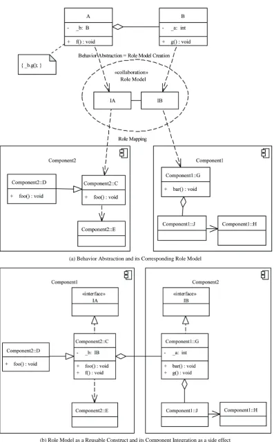
Figure 3 illustrates, in a more concrete way, how cer- tain behavior is factored out and packaged as a rolemo- del, see Figure 3(a). Then, as depicted in Figure 3(b), if we were given two components and we wish to integrate them in a manner similar to the behavior encapsulated by
(a) Decorator Class Model (b) Decorator Role Model
Figure 2. The role mapping process to arbitrary class instances.
the role model, we can pick out two objects, in this case C and G, and map roles IA and IB onto them, respec-tively. Since, the role model constitutes one specific col-laboration to accomplish a certain task that involves two objects, the new objects that assume those roles will col-laborate in similar manner. Therefore, by the virtue of this collaboration, we were able to combine (integrate) Component1 and Component2. This will be become more evident as we go through a detailed example in Section 6. As a stylistic convention, we prefix a role name with a letter “I” to denote an “interface” in code.
4. Practice: DCI Architecture
We briefly discuss the DCI architecture and show how we adapted it to implement our compositional model. The DCI architecture was introduced by Reenskaug [11] and further elaborated on extensively by Coplien et al. [14].
In DCI, we start with the use case model as a driving force to implement an application. The architecture of an application comprises the Data part, this describes the makeup of the system, and the Interactionpart, this de-scribes system’s functionality. What connects the two dynamically is a third element called Context. Each of these three parts has physical manifestation as compo-nents during implementation. For example, there are jects to represent the applications’ domain objects; ob-jects to represent system behavior or interactions be-tween domain objects; and objects to represent use cases. The architecture is clean in that it makes a clear distinc-tion between design activities corresponding to each of
the artifacts, namely the Data, Context, and Interaction. It also makes traceability between what the user wants and where it is implemented in the code clear through the use case context construct in the architecture.
The domain objects behavioral specification is highly cohesive by making each object knows everything about its state and how to maintain it. Coplien etal. [14] refer to these domain objects as dumb objects that know noth-ing about other objects in the system. The interaction between domain objects, on the other hand, is a system functionality captured as system behavior and assigned to yet another type of objects conveniently named as inter-action objects. The DCI treats these objects as first class citizens. While the identification of domain object re-sponsibilities, i.e. object behavior, is a technique known from early days of object oriented analysis and design, check for example Wirfs-Brock etal. [15] and Coad etal. [16] who refer to this task as “Do it Myself” strategy, the interaction between objects having its own object desig-nation is a novel concept the DCI re-introduced and made it a visible modeling element in system architec-ture.
(a) Behavior Abstraction and its Corresponding Role Model
[image:5.595.101.499.76.716.2](b) Role Model as a Reusable Construct and its Component Integration as a side effect
System functionality, i.e. functionality that does not be- long to any one specific object type at design time, is injected onto roles at runtime and when any object plays that role, i.e. it has acquired a new behavior. This is ac-complished using a programming construct called Traits
first introduced by Schärli etal. [13] and is defined as “a group of methods, i.e. behavior, that serves as a building block for classes and is a primitive unit of code reuse.”
5. A Software Composition Process Using
Design Patterns
After covering theory and practical implementation strat- egy, we present the following process by which we use design patterns in their role specification as new means to integrate components. The key concepts and core ideas we borrowed from DCI architecture and adapted them for our process are: role specifications, behavior injection through “traits mechanism”, i.e. extending the function- ality of any object, and introducing a collaboration con- text similar to use case context.
1) Design each component with all the required functionality. We realize that interdependencies on services from other components are required; therefore, we assume that it may be necessary to introduce an architectural layer that provides the necessary abstraction level.
2) Determine the requirements needed for two com- ponents to interact. This step specifies the col-laboration between the components.
3) Select one design pattern that may satisfy this requirement.
4) Identify design patterns’ participant roles. 5) Code up the roles as methodless interfaces;
how-ever, some roles may contain other roles as prop-erties.
6) Identify the responsibility of each role and code it up as a Trait.
7) Select an object from each component that we need to map each role onto.
8) Map the design pattern participants’ roles to these objects. The implementation is language de-pendent, but for statically typed languages Inter-face-like implementation is common.
9) Create a context class for the collaboration to take place identified in Step 2.
6. Case Study: A Library System
We will illustrate our approach, and follow our process along the way, using a case study that we intentionally made it simple to focus on key concepts presented in this paper. We state few requirements, design a solution, and provide a complete implementation in Appendix. We numbered the code listing for easy reference. This system supports these requirements:
1) A local library has library services, resource col-lections, and administration offices.
2) A local library system uses services of a remote lending branch.
3) Library services are either simple services (books reservation, DVDs reservation, CDs reservation, and search services) or composite services. 4) Resource reservations are made by any user. 5) Users can search for resources.
6) Loanable resources, e.g. books, DVDs, and CDs, are either available or checked out.
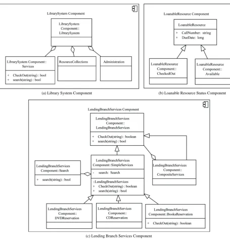
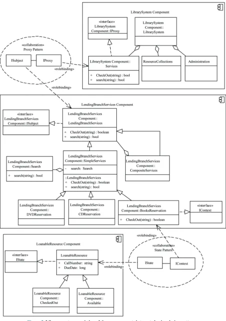
The application is decomposed into three distinct com- ponents depicted by component diagrams in Figures 4(a)-(c) corresponding to our three structural require- ments 1, 6, and 3 listed above, respectively. The intent is to integrate these three components using our proposed approach based on design patterns. The integration re- quirement comes from requirement 4 and 5 (Step 1).
Figure 5 illustrates how we intend to integrate the three components using the Proxy [2] (p. 207) and State [2] (p. 305) design patterns. We use the Proxy design pattern as an integrator because the Library Services re-lies on remote services from a lending branch. Needless to say, this is a contrived example to demonstrate the tech- nique. By similar reasoning, we opted to use the State pattern as an integrator between the Lending Branch Books Reservation Services and Loanable Resources, i.e. books, components (Steps 2 and 3). In Figure 5, we show two collaboration models corresponding to Proxy and State patterns that we will use as integrators in our case study. We will show how to code up these structures us-ing C# language. We only describe integratus-ing two com- ponents using the Proxy pattern; however, the process is exactly similar to integrating the other components using the State pattern (Step 4). In the code, lines 11-17, these roles are implemented as methodless interfaces (Step 5):
public interface ISubject {} public interface IProxy {}
In the code, lines 22 and 44, two objects, Services from the Library component and LendingBranchServices from the Lending Branch Services component, will im-plement IProxy and ISubject interfaces, i.e. roles, respec-tively (Steps 7 and 8):
public class Services: IProxy {}
public class LendingBranchServices: ISubject {}
(a) Library System Component (b) Loanable Resource Status Component
[image:7.595.62.518.80.553.2](c) Lending Branch Services Component
Figure 4. Model structure of the three individual components of the library system sample application.
we will be injecting into IProxy type object by the Trait [13] concept. In C# language, it is done through exten-sion method [17]. Extenexten-sion methods enable you to “add” methods to existing types without creating a new derived type, recompiling, or otherwise modifying the original type. Extension methods are a special kind of static method, but they are called as if they were instance methods on the extended type. This is what we did in the RequestTrait class (Step 6) line 103 in the code.
public static class RequestTrait {} public static bool Request (this IProxy
proxy, ISubject subject,
Request Type request) {} ...}
In fact this class contains the behavior associated with IProxy role that gets injected into any object taking this role, e.g. objects of class Services. In C# a Request() method extends, i.e. adds more methods, any arbitrary object with new behavior as long as it is of type IProxy in our case. This is done through the first argument of Request(this IProxy proxy,...) method.
how the DCI architecture creates a “context” class for each use case. The RequestResourceContext class is the place for this to happen (Step 9) line 153 in the code.
public class RequestResourceContext {}
As you can see, the “integration” which is based on the “collaboration” model is a construct that is quite trace-able in the code. The integration happens when we in-stantiate an object of type “RequestResourceContext”, line 195, after setting up its required parts (through its constructor) and calling its “Doit” method in the Main method of the LibrarySystemCaseStudy class, line 196. Now, you see why we call this type of integration be-havioral since it is based on a method call at runtime. Using the State pattern adds a slight complication be-cause the IContext requires IState property, lines 13-16. However, this property is of the type getter and setter whose code is easily generated by most modern interac-tive development environments. In the code, we demon-strate how a loanable resource, i.e. a book, started in Available state, line 194, checked out, line 196, and be-came available again, line 197. In the code, lines 198-199, we also demonstrate how the Search() method that was injected through IProxy role, is invoked through the in-tegration mechanism between Services and Lending-BranchServices objects.
Figure 6 is a high-level view of the components as-sembly showing the design patterns as the integration interfaces representing the wiring of the three compo-nents.
We left out some of the detailed explanation of the ra-tional behind using Traits and Methodless roles and some of the limitations of the statically typed languages, like C#, that force us to do certain things one way as opposed to dynamically typed languages where there is more flexibility of injecting a role at runtime rather than at compile time. Chapter 9 of Coplien etal. [14] has all this explained. The complete workable code, albeit skeletal, is listed in Appendix.
7. Discussion
On encountering our approach for the first time, one may get the impression it is no different from Gamma’s or Vlissides’ approaches. There is, however, a subtle dif ference in that our approach provides explicit steps to
integrate software components. The technique can be ap- plied repeatedly to any integration problem. First and-foremost the approach presented in this research is of practical importance. The theory serves only to validate the concrete implementation and provides generalization to a variety of implementation strategies. The key con-cepts to take away are these. First, design patterns’ key principal properties are used as abstraction modeling constructs through collaboration. These, then become traceable artifacts through “context” classes in the code. Second, the proposed approach allows for partial and evolutionary design. Recall, that the collaboration model captures all the integration requirements by the virtue of the role model it encapsulates. Third, role to object map-ping is really a binding mechanism that could be utilized effectively by this duality principle: either domain ob-jects discovery or object roles allocation can be deferred. In other words, you can begin design with domain ob-jects if you have settled on all of them, or you can begin design with roles required behavior and then map or bind them to objects at a later time. The latter gives you the most flexibility. Last, we provide a process anyone can learn and follow methodically.
Could we have used a different pattern to integrate? Absolutely, and which one we choose depends on re-quirements. Let’s say that the Search() method of Ser-vices class and the Search() method of the Lending-BranchServices class had incompatible interfaces. In that case, we could use the Adapter pattern [2] (p. 139) whose participants have the roles of IAdpater and IAdaptee. The behavior of the Adapter role, i.e. adapting a generic Re-quest to a Specific ReRe-quest, would have been the trait class.
Is any design pattern suitable as an integrator? It de-pends on how well you structure your composition prob-lem in such a way that matches the design probprob-lem a specific design pattern intends to solve. In addition to reuse, design patterns promote flexible designs; by the same argument one can use design patterns to create flexible architectural compositions. This is one of the characteristics of maintainability which is a desired de-sign quality attribute.
[image:9.595.60.542.659.718.2]The design and the implementation approach we pre-sented creates a new design paradigm that appears com-plex at first but once learned, it becomes another power-ful tool added to architect’s and designer’s skill set. The
compositional model requires creating abstractions out of behavioral collaboration models of design patterns. Al- though this type of integration has richer semantics, it is not as straight forward as using the traditional techniques like aggregation or generalization. It forces you to think and design in the abstract something not many feel com-fortable with. Furthermore, since the implementation strategy follows, more or less, the DCI architecture foot-steps, it also suffers from some of the added overhead introduced by that architecture, as discussed in Coplien et al. [14] (pp. 294-297).
8. Conclusion and Future Work
We have introduced a conceptual framework and an im-plementation model for software composition using de-sign patterns. We have also created a process that should guide practitioners and first time learners, learning how to use design patterns, in assembling individual compo-nents. That is our contribution. The compositional model can also be used for non-pattern-based components. The approach is scalable without adding complexity and should work with any design pattern once its collaboration model is identified. The rational used to select a design pattern to solve design problems should also work for selecting a design pattern to solve integration problems.
For future research, there is an opportunity to automate some of the implementation tasks with proper code gen-erators, e.g. metaprogramming techniques available in some development frameworks like .NET [18]. Code in-jection through Reflection could easily be accomplished at compile time. Also, since the approach allows defer- ing the integration until a later stage in the development cycle, it gives an opportunity for architects or designers to identify a variationpoint, i.e. integration strategy, with
variants [19].
Finally, to evaluate this proposed compositional model against other ad-hoc approaches, we intend to conduct a design experiment that is formal, rigorous, and controlled based on techniques from experiments in software engi-neering [20]. This effort is part of future work.
Acknowledgements
The open access support for this work was supported by the Illinois Institute of Technology.
REFERENCES
[1] S. Hasso, “A Uniform Approach to Software Patterns Classification and Software Composition,” Ph.D. Thesis, IIlinois Institute of Technology, 2007.
[2] E. Gamma, R. Helm, R. Johnson and J. Vlissides, “De-sign Patterns,” Addison Wesley, Reading, 1995.
[3] J. Vlissides, “Pattern Hatching: Design Patterns Applied
of Software Patterns,” Addison Wesley, Reading, 1998.
[4] L. Bass, P. Clements and R. Kazman, “Software Archi-tecture in Practice of SEI Series in Software Engineeer-ing,” 2nd Edition, Addison-Wesley Professional, Boston, 2003.
[5] S. M. Yacoub and H. H. Ammar, “Pattern-Oriented Ana- lysis and Design (POAD): A Structural Composition Ap- proach to Glue Design Patterns,” 34thInternationalCon-
ference on Technology of Object-Oriented Languages andSystems, Santa Barbara, 30 July-04 August 2000, pp. 273-282.
[6] D. Riehle, “Describing and Composing Patterns Using Role Diagrams,” Proceedings ofthe 1996 Ubilab Con-ference, Zurich, 1996.
[7] T. Taibi, “Formalizing Design Patterns Composition,”
TheIEE-ProceedingSoftware, Vol. 153, No. 3, 2006, pp. 127-136. http://dx.doi.org/10.1049/ip-sen:20050072
[8] H. B. Enderton, “A Mathematical Introduction to Logic,” Academic Press, 2nd Edition, 2000.
[9] L. Lamport, “The Temporal Logic of Actions,” ACM Transactions on Programming Languages and Systems
(TOPLAS), Vol. 16, No. 3, 1994, pp. 872-923. http://dx.doi.org/10.1145/177492.177726
[10] OMG, “OMG Unified Modeling Language (OMG UML), Superstructure,” 2.4.1 Edition, Object Management Group, 2011.
[11] T. Reenskaug and J. O. Coplien, “The DCI Architecture: A New Vision of Object-Oriented Programming,” 2009. http://www.artima.com/articles/dci_visionP.html
[12] T. Reenskaug, “Working with Objects: The OOram Soft- ware Engineering Method,” Manning Publications, 1996.
[13] N. Schärli, S. Ducasse, O. Nierstrasz and A. P. Black, “Traits: Composable Units of Behaviour,” Proceedingsof European ConferenceonObject-Oriented Programming
(ECOOP’03), Vol. 2743, pp. 248-274.
[14] J. Coplien and G. Bjørnvig, “Lean Architecture: For Ag-ile Software Development,” 1st Edition, WAg-iley, West Sussex, 2010.
[15] R. Wirfs-Brock and A. McKean, “ObjectDesign:Roles,
Responsibilities, and Collaborations,” Addison-Wesley, Boston, 2003.
[16] P. Coad, D. North and M. Mayfield, “Object Models: Strategies, Patterns, and Applications,” Yourdon Press, Upper Saddle River, 1997.
[17] Microsoft Corp, “C# Programming Guide: Extension Methods,” 2012.
http://msdn.microsoft.com/en-us/library/vstudio/bb38397 7.aspx
[18] K. Hazzard and J. Bock, “Metaprogramming in .NET,” Manning Publications Co., Shelter Island, 2013.
[19] K. Phol, G. Böckle and F. van der Linden, “Software Pro- duct Line Engineering: Foundations, Principles, and Te- chniques,” Springer, Heidelberg, 2010.
Pub-lishers, Boston, 2000.
http://dx.doi.org/10.1007/978-1-4615-4625-2
[21] S. Hasso, “Design Patterns as Connectors Source Code on
GitHub,” 2014.
Appendix
This is a complete skeletal code listing in C# language. Please refer to Section 6 for discussion and Figure 5 for the class model of the three components we are composing to make up the final application. The complete Visual Studio solution can be downloaded from GitHub [21].
1 2 3 4 5 6 7 8 9 10 11 12 13 14 15 16 17 18 19 20 21 22 23 24 25 26 27 28 29 30 31 32 33 34 35 36 37 38 39 40 41 42 using System; using System.Collections.Generic; using System.Linq; using System.Text; namespace Roles {
// role declaration: a place holder with methods (behavior)
// declared to populate any object, i.e. any object // willing to take this role
public interface ISubject { } public interface IProxy { } public interface IContext {
IState State { get; set; } }
public interface IState { } }
namespace LibrarySystem {
using Roles;
public class Services : IProxy {
public Services() { } }
public class Administration { } public class ResourceCollections { } public class Resort
{
// properties
public Services Services { get; set; }
public Administration Administration { get; set;}
public ResourceCollections ResourceCol-lections { get; set; }
}
public enum RequestType { BooksReservation, DVDReservation, CDReservation, EntertainmentPkgReservation, Search } } namespace LendingBranchServices { using Roles; 43 44 45 46 47 48 49 50 51 52 53 54 55 56 57 58 59 60 61 62 63 64 65 66 67 68 69 70 71 72 73 74 75 76 77 78 79 80 81 82 83 84 85 86 74 88 using LibrarySystem;
public class LendingBranchServices : ISubject {
public LendingBranchServices() { }
public virtual bool CheckOut() { return true; }
public virtual bool search(string callNum) { return true; }
}
public class SimpleServices : LendingBranch-Services
{
Search _search;
public SimpleServices() { _search = new Search(); }
public override bool search(string callNum) { Console.WriteLine("SimpleServices search operation"); return true; } }
public class BooksReservation : SimpleServices, IContext
{
public override bool CheckOut() {
Con-sole.WriteLine("LoanableResource reservation op-eration");
return true; }
public IState State { get; set; } }
public class Search {
public Search() { }
public bool search(string callNumber) { Console.WriteLine("Search opera-tion"); return (true); } } } namespace LoanableResource { using Roles;
public class LoanableResource : IState {
public string CallNumber { get; set; } public long DueDate { get; set; } }
89 90 91 92 93 94 95 96 97 98 99 100 101 102 103 104 105 106 107 108 109 110 111 112 113 114 115 116 117 118 119 120 121 122 123 124 125 126 127 128 129 130 {
public CheckedOut() { Con-sole.WriteLine("CheckedOut"); }
}
public class Available : LoanableResource {
public Available() { Con-sole.WriteLine("Available"); } } } namespace CaseStudy { using Roles; using LibrarySystem; using LendingBranchServices; using LoanableResource;
//methods/behavior is injected into whoever assumes IProxy role
public static class RequestTrait {
public static bool Request(this IProxy proxy, ISubject subject, RequestType request) {
bool rc = false;
IContext ctxt = subject as IContext; IState book = ctxt.State;
HandleBookReservationContext brContext = new HandleBookReservationCon-text(ctxt, book);
switch (request) {
case Request-Type.BooksReservation:
rc = brContext.Doit(); break;
case RequestType.Search: LendingBranchServices ra = subject as LendingBranchServices;
string callNum = (book as LoanableResource).CallNumber;
rc = ra.search(callNum); break;
default:
Console.WriteLine("{0}: unrecognized request", request);
rc = false; break; }
return (rc); }
}
// Behavior Handle() is injected into State ob-jects
public static class HandleTrait
131 132 133 134 135 136 137 138 139 140 141 142 143 144 145 146 147 148 149 150 151 152 153 154 155 156 157 158 159 160 161 162 163 164 165 166 167 168 169 170 171 172 173 {
public static bool Handle(this IState state, IContext ctxt)
{
bool rc = false;
Type tt = ctxt.State.GetType(); string typeName = tt.ToString(); LoanableResource book = ctxt.State as LoanableResource;
switch (typeName) {
case "LoanableRe-source.Available":
ctxt.State = new Checke-dOut() { CallNumber = book.CallNumber, DueDate = book.DueDate };
rc = true; break;
case "LoanableRe-source.CheckedOut":
ctxt.State = new Available() { CallNumber = book.CallNumber, DueDate = book.DueDate }; break; default: break; } return (rc); } }
// LoanableResource reservation ‘use case’ public class RequestResourceContext {
// properties
public IProxy Proxy { get; private set; } public ISubject Subject { get; private set; } public RequestType ReqType { get; private set; }
public RequestResourceContext(ISubject subject, IProxy proxy,
RequestType resource) {
Proxy = proxy; Subject = subject; ReqType = resource; }
public bool Doit() {
bool rc = Proxy.Request(Subject, ReqType);
return (rc); }
}
174 175 176 177
178 179 180 181 182 183 184 185 186 187 188 189 190 191 192
193 194
195
196 197 198
199 200
201 202 203 204
{
public IState State { get; private set; } public IContext Context { get; private set; } public HandleBookReservationCon-text(IContext ctxt, IState state)
{
State = state; Context = ctxt; }
public bool Doit() {
bool rc = State.Handle(Context); return (rc);
} }
class LibrarySystemCaseStudy {
static void Main(string[] args) {
// demonstrate Subject pattern integra-tion
Services services = new Services(); SimpleServices ra = new BooksRe-servation() { State = new Available() { CallNumber = "123", DueDate = 12202013 } };
RequestResourceContext integration = new RequestResourceCon-text(ra,services,RequestType.BooksReservation); bool rc = integration.Doit(); rc = integration.Doit();
integration = new RequestResource-Context(ra, services, RequestType.Search);
rc = integration.Doit();
Console.WriteLine("press any key to exit...");
Console.ReadKey(); }