Weighted Cluster based Distributed Spanning Tree
Routing Protocol for Mobile Ad-hoc Networks
Poonam Pahuja
Research Scholar, Mewar University, Chittorgarh,Rajasthan, India
Tarun Shrimali,
Ph.D Research Supervisor Mewar University, Chittorgarh,Rajasthan, India
ABSTRACT
MANETs do not have any fixed infrastructure and consist of wireless mobile nodes that perform various data communication tasks. Mobile ad hoc networks (MANETs) are collection of distributed nodes which communicate using multi-hop wireless links with frequent node mobility. The frequent mobility of nodes leads network partition and futile communication. So, there need an interconnection technique that should guarantee network connectivity, efficient routing and maintain network performance in MANET. Clustering has become an important approach to manage MANETs.
This paper proposed Weighted Cluster Based Distributed Spanning Tree (WCBDST) routing technique to form better MANETs interconnections. WCBDST is an interconnection technique in which nodes of MANETs are made to form a forest of spanning tree with root node as cluster head in a distributed fashion which improved routing, network connectivity and maintains network performances.
Keywords
MANET, WCBDST, DST, Cluster Head, Mobile Node, NS2
1.
INTRODUCTION
A Mobile Ad-Hoc Network (MANET) is an autonomous system of mobile nodes connected by wireless links. The nodes are free to move randomly and organize themselves arbitrarily. Every node in a MANET works as a source and a sink, and also relays packets for other hosts and is thus a router as well. This type of network can be used in sensor networks, fire, safety, rescue, disaster recovery operations, conference and campus settings, car networks, personal area networking, etc [1]. MANETs have similar characteristics to other wireless communication networks, which are mainly attributed to the wireless channel‟s properties. A wireless channel is error-prone, which means that link bandwidth and packet delay are unpredictable due to multi-path fading, interference, and shadowing. Besides this common characteristic, MANETs have their own features: they are autonomous and infrastructure less; they utilize multi- hop routing; they support a dynamic topology; the nodes are energy constrained; the bandwidth is limited; and they are self creating, self-organizing and self-administering [2]. Distributed spanning tree structure is organized into a hierarchy of groups. The nodes are put together in groups and groups are gathered in groups of higher level, recursively. This organization, built on top of routing tables allows the instantaneous creation of spanning trees rooted by any nodes and keeps the load balanced between the nodes [6][7][8].
2.
WEIGHTED CLUSTER BASED
DISTRIBUTED SPANNING TREE
(WCBDST)
A number of clustering algorithms have been proposed and based on some criteria to choose cluster head such as speed and direction, mobility, energy, position and number of neighbors of a given node. These works present advantages but some drawbacks as a high computational overhead. WCBDST systematize MANETs into a hierarchy of groups of nodes with weighted clustering. The nodes are put together in group‟s recursively. This systemization is built on top of routing tables allows effective routing in MANET.
2.1
Assumption
In the network each node is indexed (id) i.e., 1, 2, 3…, n where n is the number of nodes in the network. The basic assumptions followed in the algorithm design as,
i) Each node has limited power (battery) transmission. ii) Each node has a sense of direction of incoming signals
from the neighborhood
iii) Each node has a unique id, which can be the MAC layer address.
iv) Each node broadcasts; each node was capable of hearing, receiving and replying with acknowledgment.
v) Each node is a router. That is, each node is both a relay and a receiving station.
vi) The network topology is static during the execution of the clustering algorithm.
vi) Each mobile node joins exactly one cluster-head.
vii) The optimal number of nodes in the cluster α is assumed to be 8.
2.2.
Formation of Cluster
Initially each node is assigned a unique ID value. It broadcasts its ID value to its neighbors and builds its neighborhood table. Each node calculates its own weight based on the following factors:
i) Number of neighbors (nN): The number of nodes that can communicate directly with the given node i.e. that are in its transmission range.
ii) Node energy (nE): The power currently left in each node. The energy is consumed by sending and receiving of messages. iii) Mobility (nM): Running average of speed of each node. If mobility is less, the node is more suitable to become cluster head CH.
20 Initially, each node broadcasts a beacon message to notify its
presence to the neighbors. A beacon message contains the state of the node. Each node builds its neighbor list based on the beacon messages received. The cluster-heads election is based on the weight values of the nodes and the node having the lowest weight is chosen as CH. Each node computes its weight value based on the following algorithm:
2.3 Cluster Weight Algorithm
Step 1: The coefficients used in weight calculation are assumed the following values w1=0.7, w2=0.05, w3=0.05, w4=0.2; The sum of these co-efficient is 1.This is actually used to normalize the factors such as number of neighbors, distance with its neighbors, mobility of the node, and power consumed used in the calculation of weight of a node. The factors number of neighbors (nN) and distance with its neighbors (nD) are given more importance and assumed higher co-efficient values 0.7 and 0.2 respectively
Step 2: Compute the difference between the optimal cluster‟s size „α‟ and the real number of neighbors „R (V)‟as number of neighbors.
𝑛𝑁 = 1 − (| α − R (V)| / α) (1) Step 3: For every node the sum of the distances, nD, with all its neighbors is calculated.
𝑛𝐷 = Σdist(v, v’) where v’ €N(v) (2) Step 4: Calculate the average speed for every node until the current time T. This gives the measure of the mobility nM based on the X co-ordinate and Y co-ordinate i.e. position of the node v at all previous time instance t.
Step 5: Determine how much battery power has been consumed as nE. This is assumed to be more for a cluster head when compared to an ordinary node because cluster head has taken care of all the members of the cluster by continuously sending the signal.
Step 6: The weight nW for each node is calculated based on 𝑛𝑊 = (𝑤1 × nN ) + (𝑤2 × nE ) + (𝑤3 × n𝑀 ) + (𝑤4 ×
nD ) (3)
Step 7: The node with the smallest nW is elected as a cluster head. All the neighbors of the chosen cluster head are no more allowed to participate in the election procedure.
Step 8: All the above steps are repeated for remaining nodes which is not yet elected as a cluster head or assigned to a cluster.
The WCBDST Algorithm uses five procedures. Firstly WCBDST_initialize() is a procedure which initializes WCBDST by creating Cluster Head (CH) and the procedure creates an array on each CH to hold its MN details. Each CH is provided with unique Priority Number (PN) to provide write priority among the CHs. WCBDST_initialize() also set CH id field of node as their own id and then it calls the procedure WCBDST_probe().
Algorithm WCBDST_initialize()
Step1: Broadcast a beacon signal to all its neighbor nodes in the transmission range;
Process the beacon signals received from the neighbor nodes in the network and form the connection matrix, CM;
Step2: Calculate weight of node n, as nW as above cluster weight computational algorithm;
Step3: Broadcast weight value nW to all its neighbor nodes; Process the signals received from the neighbor nodes in the network and identify the weights of the neighbors;
Step4: Find the node with minimum weight in the neighborhood;
If (nW is the least weight)
Declare itself as the cluster head;
Else
Send request to join the cluster formed by the neighbor with least weight;
Step5: N(i) is Cluster Head where i=1….n array a[n] to hold its member node details
N(i).setHead(N(i))
assign unique Priority for N(i) call WCBDST_probe()
Algorithm WCBDST_probe()
{
for j = 1 tom do {
/* where m is no. of peers within the range of N(i) */ create probe message pmsg
set pmsg.id = N(i) send(pmsg, m) }
}
Algorithm WCBDST_receive(msg)
{
if(msg = =pmsg) {
cast msg to pmsg if(N(i) = = Cluster Head )
delete(pmsg) else
if(N(i) is under any Cluster Head)
delete(pmsg) else {
id = pmsg.getId
N(i) is under N(id) N(i).setHead(N(id)) WCBDST-reply(N(id)) WCBDST_forward(pmsg) }
}
else if(msg==reply)
cast msg to rmsg if(N(i) != Cluster Head )
send(rmsg,N(id)) else
dest = rmsg.getDest if(dest==N(i))
{
d = rmsg.getId a.add(id) }
else
send(rmsg,N(id)) }
Algorithm WCBDST_reply(N(id))
{ create reply message rmsg set rmsg.id = N(i)
}
Algorithm WCBDST_forward(pmsg)
{ forj = 1 to m-1 {
/* where m is no. of peers within the range of N(i) except peer from where it received probe */
copy pmsg message send(pmsg, m) }}
The algorithm WCBDST_probe(), which is called by every CH creates probe message and set „id‟ field of message as its own id and flood the message to all nodes it is connected. On receiving a message every node execute the procedure WCBDST_receive(msg) where „msg‟ is the received message. During WCBDST formation it should be possible to get any one of the two types of messages, the probe message or reply message:
If there is a probe message, any one of the following would be occurred:
Case-1: If the message is received by a CH, then it is just discarded.
Case-2a: If the message is received by a MN which is not under any CH, then MN stores the Head variable as the id which it read from pmsg. Then call the procedures WCBDST_reply(N(id)) and WCBDST_forward(pmsg). Case-2b: If the message is received by a mobile node N which is under any CH then it just discard the message.
If there is a reply message, any one of the following would be occurred:
Case-1: If the message is received by a MN, then it just forwards it to the node bearing the id „id‟.
Case-2: If the message is received by a CH, then it reads „dest‟ from „rmsg‟, if „dest‟ equals N(id) it shows required CH is reached. It read „id‟ from „rmsg‟ and add it to its array, otherwise it is forwarded to N(id).
Algorithm WCBDST_reply(N(id)) is called by MN to reply to its CH. The MN creates a reply message. The „id‟ and „dest‟ fields of the reply message is set to be, the „id‟ of the MN and the „id‟ of the CH respectively. After the reply message sent to CH, the MN calls the algorithm WCBDST_forward(pmsg) to flood the probe message to all the nodes except the node from where it was received.
After the completion of these five algorithms the MANET will be in required DST structure
Definition 1: Let Gm be the MANETs graph based on the formation of CH and MNs. Then Gm can be represented as,
𝐺𝑚 = 𝐷𝑆𝑇1 𝐷𝑆𝑇2 𝐷𝑆𝑇3 … 𝐷𝑆𝑇𝑛
=
𝐶𝐻1, 𝑀𝑁1, 𝑀𝑁2 … . 𝑀𝑁𝑗 𝐶𝐻2, 𝑀𝑁1, 𝑀𝑁2 … . 𝑀𝑁𝑗 𝐶𝐻3, 𝑀𝑁1, 𝑀𝑁2 … . 𝑀𝑁𝑗
…
𝐶𝐻𝑛, 𝑀𝑁1, 𝑀𝑁2 … . 𝑀𝑁𝑗
(4)
where,
- „Gm‟ is graph of MANET with „m‟ nodes.
- „CH‟ is the Cluster Head (CH). „i‟ is the number of CH formed in the MANET.
- „MN‟ is the Member Node (MN). ‘j’ is the number of MN formed under every CH in the MANET.
- „DST‟ is the Distributed Spanning Tree formed in MANET. „k‟
is the number of DSTs formed in MANET and ‘i’ equals ‘k’.
Thus the graph of MANETs (e.g. Gm) of „m‟ nodes is organized into „k‟ DSTs. Each DST consists of a CH and „j‟ number of MNs corresponding to the CH. Thus each node required m/k entries in their routing table.
2.4 Cluster Maintenance
Two types of operations for cluster maintenance: the battery power threshold property and the node movement to the outside of its cluster boundary.
2.4.1
Node Movements
The node movements can be in the form of node joining or node leaving a cluster. These operations will have only local effects on the clustered topology if the moving node is a MN node. If the leaving node is CH node, the cluster reorganization has to be performed for the nodes in the cluster by evoking the clustering algorithm.
Algorithm for node movements
Step1: Broadcast a beacon signal to all its neighbor nodes in the transmission range;
Process the signals received from the neighbor nodes in the network and form the connection matrix, CM;
Step2: Calculate the Degree R(U) using CM, number of neighbors (nN), sum of the distances, nD, with all its neighbors, Average speed of the node, nM, Amount of battery power that has been consumed, nE, and Weight of node N as nW;
Step3: If (A Cluster head already exist in the neighborhood) Send request to join the cluster; Else
Form a new cluster and declare itself as the cluster-head;
2.4.2
Battery Power Threshold
The battery power of the nodes participating in the clustering changes continuously. The cluster heads Power decreases more rapidly when compared to the cluster members. When the cluster heads Battery Power falls below a threshold then the node is no longer able to perform its activates and a New Head from the members available need to be chosen.
Algorithm Cluster-head power
Step1: Verify the threshold on the cluster head‟s battery power;
If (Battery power < Threshold)
Cluster head sends a LIFE_DOWN message to all its Neighbors;
All the member nodes participate in the Re-election procedure using Weighted Cluster Algorithm and the node with least weight is selected as the new cluster head;
Else
Re-election is not needed;
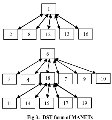
3. DST FORMULATION
22 When nodes receive the probe message, it comes under the CH
[image:4.595.321.516.74.282.2]from which it was received and floods it out. Fig. 3 shows nodes 8 and 12 get probe message from node 1. It saves their CH id as 1 and then acknowledge to its CH (node 1) and also floods the probe message to all the node it connected except to the sender (node 1).The same happens in nodes 4,5,9,7,17 and 15. The probe message from node 8 is received b y nodes 2 and 13 and acknowledged to node 1 and flooded. Likewise nodes 3 and 10 come under CH 6 and node 14 and 11 come under CH 18 as shown in Fig.3. The notable thing is that the node 15 forwards the probe message to 11 and 9, but node 9 is already under CH 6. So, it just deletes the probe instead of processing the message.
[image:4.595.55.290.217.437.2]Fig 1: A MANETs and its node with wireless range
Fig 2: MANETs and Node connectivity
Fig 3: DST form of MANETs
4. SIMULATION AND PERFORMANCE
ANALYSIS
The mobile network model assumed in this paper consists of random number of mobile nodes with each node having fixed energy and random mobility. The number of nodes can be determined initially. The transmission range of each node can also be specified and each node can pass messages to all the nodes in its transmission range. The mobility has been provided by assigning a random value to each node. If the value of random number is greater than some specified value then the node is mobile otherwise it is stationary. A mobile node moves to some random direction for random interval and then changes its direction to a new random location. New nodes can also randomly be added to the network. Further each node starts with some energy and its energy decreases each time it passes a message. A node fails if its whole energy has been consumed. A failed node is represented as a black node.
The performance of the proposed WCBDST routing technique is compared with AODV [5] using NS2 simulation tool.
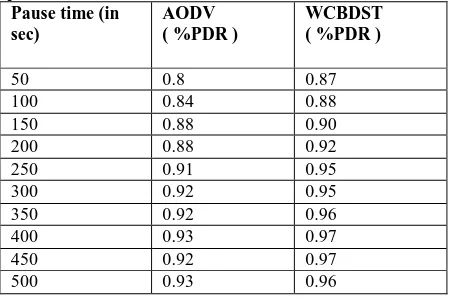
4.1
Packet Delivery Ratio
The Packet Delivery ratio is based on the number of packets delivered and number of packets sent. Higher the Packet Delivery Ratio (PDR) better is the performance of the Cluster. The CBDST technique approaches a ratio of one or 100% delivery as the network becomes more static. Only under dynamic conditions the packets collide or the packets are lost. As the pause time increases the Static nature is enhanced.
4.2
Scalability
The Scalability analysis is measured in Table 2 by varying the number of source nodes in the network to create congestion. The source nodes variations range from 10 to 100 mobile node pairs. The speed of the source nodes is varying at 10m/s. The connectivity maintenance gives the number of source nodes connected. The connectivity of nodes gives path for data packets to be forwarded without loss and comparison results are shown in the table 2.
1
2
3
12 13 161
2
3
12 13 161
2 8 12 13 16
6
3
4
5 7 99
10 1
2
3
12 13 161
2
3
12 13 1618
11 14 15 17 19
15 1
2
3 4
6 5
7 8
9 10
11
14 13
12
16
17
18 19
15 1
2
3 4
6 5
7 8
9
10
11
14 13
12
16
17
Table 1 Packet Delivery Ratio for Mobility with 10m/s speed
Pause time (in sec)
AODV ( %PDR )
WCBDST ( %PDR )
50 0.8 0.87
100 0.84 0.88
150 0.88 0.90
200 0.88 0.92
250 0.91 0.95
300 0.92 0.95
350 0.92 0.96
400 0.93 0.97
450 0.92 0.97
500 0.93 0.96
[image:5.595.54.281.92.242.2]Simulation is done using NS2 with varying node count ranging from 10 to 100 is used to study the percentage of connectivity in wireless environment. Maximum possible connectivity is 100% where each node is connected with every other node.
Table 2 Connectivity for Scalability with 10 m/s speeds
Number of Transmitting nodes
AODV
Connectivity (%)
WCBDST Connectivity (%)
10 0.7 0.72
20 0.74 0.75
30 0.78 0.8
40 0.84 0.88
50 0.89 0.91
60 0.88 0.95
70 0.9 0.96
80 0.88 0.97
90 0.87 0.97
100 0.85 0.96
5.
CONCLUSIONS
Simulation result shows weighted cluster based distributed spanning tree routing technique perform well over AODV routing protocol. This routing management guaranteed network connectivity, efficient routing and maintain network performance in MANET using distributed spanning tree models. The WCBDST also reduced routing table entries and message passes.
6.
ACKNOWLEDGMENTS
We thank anonymous referees for their valuable comments which helped in improving the content and presentation of the paper. We thank vice chancellor and director research of Mewar University, Chittorgarh, Rajasthan for always encouraging for the best.
7.
REFERENCES
[1] S. Corson, J. Macker, “Mobile Ad hoc Networking (MANET), Internet Draft, Oct. 1998.
[2] S. Lee, J. Hsu, R. Hayashida, M. Gerla, and R. Bagrodia, “Selecting a Routing Strategy for Your Ad hoc Network,” Special issue on Advances in Computer Communications and Networks: Algorithms and Applications, vol. 26, no. 7, pp. 723-733, May 2003.
[3] C. Perkins and P. Bhagwat, “Highly Dynamic Destination Sequenced Distance Vector Routing (DSDV) for Mobile Computers,” in ACM SIGCOMM, pp. 112-120 Oct. 1994.
[4] David B. Johnson, David A. Maltz, and Josh Broch, “DSR: The Dynamic Source Routing Protocol for Multi-Hop Wireless Ad Hoc Networks,” in Ad Hoc Networking, edited by Charles E. Perkins, Chapter 5, pp. 139-172, Addison-Wesley, 2001.
[5] C. Perkins, E. Belding-Royer, and S. Das, “Ad Hoc On Demand Distance Vector (AODV)”, 2003
[6] P.H.J. (2005), “A Survey of Clustering Schemes for Mobile Ad Hoc Networks”, IEEE Communications Surveys and Tutorials, Vol. 7, No. 1, pp. 32-48. Routing,” IETF RFC3561, July 2003.
[7] Yu .J.P. & Chong P.H.J. (2005) , “A Survey of Clustering Schemes for Mobile Ad Hoc Networks”, IEEE Communications Surveys and Tutorials, Vol. 7, No. 1, pp. 32-48.
[8] Deniz Cokuslu Kayhan Erciyes and Orhan Dagdeviren, “A Dominating Set Based Clustering Algorithm for Mobile Ad hoc Networks”, Springer Computational Science – ICCS (2006).
[9] P. Victer Paul, T. Vengattaraman, P. Dhavachelvan & R. Baskaran, “Improved Data Cache Scheme Using Distributed Spanning Tree in Mobile Ad-hoc Network”, International Journal of Computer Science & CommunicationVol. 1, No. 2, July-December (2010).