International Journal of Computer Applications (0975 – 8887) Volume 90 – No 11, March 2014
TraceCases: A Simulator for RUP Use-Case Analysis
Pallavi Pandit
Medi-Caps Institute of Technology and Management
A.B. Road, Pigdamber Rau, Indore
Meena Sharma
Institute of Engineering and Technology Khandwa Road
Indore, MP
ABSTRACT
Learning styles of different learners vary. So, different approaches to explaining theoretical concepts should be followed. TraceCases is a simplified tool for understanding RUP Use-Case Analysis. A use-case model is given as input, validated and analysis classes are derived and shown. Metrics for use-case model and analysis classes are computed. Traceability between use-case model and analysis classes is illustrated.
General Terms
I.6.4 [Simulation and Modeling]: Model Validation and Analysis - Experimentation
Keywords
Pedagogy, use cases, analysis classes, VOPC class diagram, traceability, metrics.
1.
INTRODUCTION
Different learning patterns of students were observed while taking a survey of a Software Design course[1]. Each student exhibited a different capability to learn based on the personality types of students.
In their paper, Thomas, Ratcliffe, Woodbury, and Jarman (2002) closely observed the learning styles of 107 introductory computer science students and concluded that there were slightly more active than reflective learners, a vast majority of visual learners over verbal, and almost equal in number of sensing or intuitive and sequential or global learners.[1]
Many empirical studies have explored the relationship between the Myers-Briggs Type Indicator (and its numerous associated factor types-Extraversion, Sensing, Thinking, Judging, Introversion, Intuition, Feeling and Perceiving) and software engineering.[1]
The traditional methods of teaching do not take the above factors into account and focus mainly on the textual aspect of learning. The aforementioned studies draw our attention to the fact that the blackboard style of teaching does not suffice to exploit the learning patterns of each and every kind of student. Some students find it difficult to engage themselves totally with the chalk-and-talk learning paradigm. The recommended different types of learning methodologies which can enhance the grasping power of students may include case studies, hands-on activities and other simulating approaches.
TraceCases employs a simplified approach for demonstrating RUP concepts to students. Its purpose is giving them an
introductory hands-on on the analysis and design discipline, mainly focusing on the use case analysis activity.
2.
LITERATURE SURVEY
The authors in [2] have introduced a new strategy for teaching RUP and UML in Software Engineering Courses to decrease the learning time and increase the skills of the students. They have incorporated the software engineering process workflow with RUP and UML. New innovations using multimedia resources and support tools were used to explain RUP and UML to the students. The authors have prepared flash tutorials to demonstrate the “how-to’s”, to cover specific knowledge and to reduce practice gaps (How to create an RUP project, how to pass from the Business model to the Requirements Model, etc.). Their learning model makes some changes in RUP workflows and models to suit the better needs of students. As a result of their new strategy, learning period in the first four phases of RUP has been dramatically reduced.
Jan Bergandy in [3] takes on a new approach to teaching RUP wherein the course contents have the RUP process framework integrated with the Software Engineering course curriculum. The students are required to develop a medium sized project for a real customer. RUP was chosen as the process framework both for the project and served as a structure for organizing the contents of the software engineering course.
3.
RUP USE CASE ANALYSIS
Rational Unified Process is the result of adopting the best practices of all the different methodologies. It has unified different aspects of object-oriented development, hence the name “Unified Process”.
3.1
The purpose of the RUP Use case
Analysis activity is [4]:
3.1.1 To identify the classes that perform the various flows of events in a use case.
3.1.2 To distribute use case behaviour to these classes, by creating use case realizations.
3.1.3 To identify and assign the responsibilities, attributes and associations to these classes.
To note the need of architectural mechanisms to provide the functionality specified by the use case, and the software system as a whole.
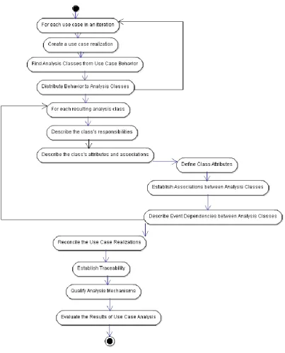
3.2
Steps of RUP Use-Case Analysis
Activity
Fig 1: Steps of Use Case Analysis
3.3
Use Cases to Code
To get from use cases to code, the following steps are followed:
A Scenario (or use case) is selected on which to begin Use Case Analysis. Then, Use Case Analysis is performed (as
4.
PROPOSED METHODOLOGY
4.1
Simplified approach to RUP Use-Case
Analysis Activity
International Journal of Computer Applications (0975 – 8887) Volume 90 – No 11, March 2014
4.1.3 Use of POS Tagger for extracting nouns and verbs from scenarios
4.1.4 Manually selecting analysis classes based on the nouns, verbs and parsed information from UC model using following guidelines[6]
4.1.4.1 One Boundary Class for each actor-use case pair
4.1.4.2 One Control Class corresponding to each use case
4.1.4.3 Noun filtering technique for Entity classes
4.1.5 Selecting attributes, methods and responsibilities and assigning them to analysis classes
4.1.6 Illustration of Analysis Classes by VOPC Class Diagram
4.1.7 Derivation of UC Metrics, Class Metrics
4.1.8 Establish traceability links
4.1.8.1 Establish traceability links among use case model elements[7]
Use case to use case section
Use case to actor
4.1.8.2 Show traceability between UC Model and Analysis Classes Model (Analysis Class realizes use case)
4.2
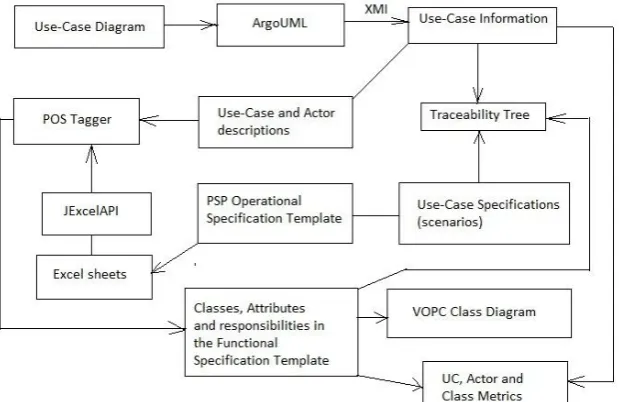
Overview of the Tool
Use-case driven development approach is widely used where use-cases form the basis of analysis, design and testing. The use-case model is subsequently mapped to analysis model, design model and test models. This paper aims to structure the case model and identify analysis classes from the use-cases and scenarios. The analysis classes can further be mapped to analysis mechanisms. TraceCases performs semi-automated use-case analysis. TraceCases also helps to establish traceability links between the use case model and the analysis model. Various metrics can be developed to quantify the use case and analysis models. Metrics for use-cases and analysis classes have been calculated using TraceCases.
An ATM Case Study is used to illustrate the working of the tool and to validate this approach.
4.3
RUP in context of PSP
This work explores RUP in the context of the Personal Software Process (PSP). Templates help us to define a software design completely. Templates in the Personal Software Process (as defined by Humphrey), have many dimensions such as Operational Specification Template, Functional Specification Template, State Specification Template and Logic Specification Template. TraceCases makes use of two templates, viz., Operational Specification Template to store the scenarios and Functional Specification Template to store classes, attributes and methods.
The proposed tool is designed using RUP combined with PSP. It has been studied that PSP Design Templates can directly be mapped to UML models and be used with the Team Software Process[8]. Hence, TraceCases can be extended to be used with the Team Software Process, and hence, be used in the industry.
5.
SIMILAR RESEARCH WORK
In their work “Automating the Transition from Use Case Model to Class Model”[9], the authors employ use cases to express the functional requirements. The use case specifications are processed using use case language schemas. These schemas reduce the ambiguity, vagueness and complexity of natural English language. A use case processing method is used to analyze the use case diagrams and use case specifications. The analysis artefacts generated include robustness and collaboration diagrams and the class diagram is generated as a design artefact. UCDA CASE tool is developed by the author for generating the diagrams automatically in Rational Rose.
The proposed work also analyzes/processes use case specifications using noun-filtering technique to extract the nouns and verbs. However, it does not use use case language schemas to process the use case specifications. TraceCases also uses XMI to extract the names of actors, use cases and association relationships from the use diagram. The tool draws the VOPC class diagram as an artefact.
In the thesis entitled “Auto-generation of Use case controllers”[10], Pushkar Marathe inputs the requirements model from use case diagram in the form of an XMI file. Then, entity, boundary and controller classes are extracted by parsing this use case diagram. His tool, called Protogen, automatically generates prototypes and hence, code for the controller classes using a hexagonal architecture.
The proposed work is a simulator for RUP. It performs use case analysis and is similar to Protogen in that it extracts entity, boundary and controller classes from a use case diagram input as XMI file. However, no code is generated for these classes. Instead, traceability diagram and metrics are derived from the use case analysis technique.
Fig 2: Architecture of TraceCases
[image:4.595.311.549.328.767.2]6.
RUP CASE STUDY: ATM
Figure 3: ATM Use case Diagram, taken from [13], redrawn in ArgoUML
[image:4.595.49.284.569.765.2]6.1
Scenario for Withdraw Cash Use Case
(Modified from [14], stored in Operational
Specification Template)
Table 1: Use case specification of withdraw cash use case
User Object
ive Withdraw cash use case
Scenar io Object ive
This use case describes how the bank customer uses the ATM to withdraw money to his/her bank account
te user
ATM bf3
The ATM displays the various list of alternatives that are available on this unit.
normal flow
bf3.1
In this case, the customer always selects "Withdraw cash"
normal flow
ATM bf4 Prompts for an account
normal flow Bank
Custo
mer bf5 Selects an account
normal flow
ATM bf6 Prompts for an amount
normal flow Bank
Custo
mer bf7 Enters an amount
normal flow
Syste m bf8
Card ID, PIN, amount and account is sent to Bank as a transaction. The Bank Consortium replies with a go/no go reply telling if the transaction is ok
normal flow Syste
m bf9 Then money is dispensed
normal flow Syste
m bf10 The Bank Card is returned
normal flow Syste
m bf11 The receipt is printed
normal flow
End bf12 The use case ends successfully
International Journal of Computer Applications (0975 – 8887) Volume 90 – No 11, March 2014
please try again".
af2.2 The use case resumes at step 4
normal flow
Altern ative Flows af3
the Bank Customer enters an amount that exceeds the withdrawal limit Amount exceeds withdraw al limit af3.1
the ATM shall display a warning message, and ask the Bank Customer to reenter the amount
af3.2 The use case resumes at step 7
Altern ative Flows af4
the Bank response indicates the daily withdrawal limit has been exceeded (this is determined by the Bank and depends upon the specific account)
Amount exceeds daily withdraw al limit af4.1
The ATM shall display a warning message, and ask the Bank Customer to reenter the amount
af4.2 The use case resumes at step 7
Altern ative Flows af5
the Bank Customer enters an amount that exceeds the amount of cash available in the ATM
Insufficie nt cash
af5.1
The ATM will display a warning message, and ask the Bank Customer to reenter the amount
af5.2 The use case resumes at step 7
Altern ative Flows af6
there is no response from the Bank within 3 seconds
No Response From Bank
af6.1
The ATM will re-try, up to three times
af6.2
If there is still no response from the Bank, the ATM shall display the message "Network unavailable – try again later". af6.3 The ATM shall return the card
af6.4
The ATM shall indicate that it is "Closed"
af6.5
The use case ends with a failure condition
Altern ative Flows af7
the money is not removed from the machine within 15 seconds
Money Not Removed
af7.1
the ATM shall issue a warning sound and display the message "Please remove cash"
af7.2
If there is still no response from the Bank Customer within 15 seconds the ATM will re-tract the money and note the failure in the log
af7.3
the use case ends with a failure condition
Altern ative Flows
If at point prior to step 8 in the basic flow the Bank Customer selects Quit Quit The ATM shall print a receipt indicating the transaction was cancelled
The ATM shall return the card The use case ends
6.2
Traceability Identifiers [15] of the use
case specification:
bf2->af1, bf8->af2, bf7->af3, bf8->af4, bf7->af5, bf8->af6, bf9->af7
6.3
Analysis classes identified from the
scenario
6.3.1
Entity Classes
CustomerATM
Card
6.3.2
Boundary Classes (one class for each use
case-actor pair)
Withdraw cash – Bank Customer pair generates WithdrawCashForm
Withdraw cash – Bank pair generates MonitorWithdrawCashForm
6.3.3
Control Classes (at least one controller
class per use case)
Withdraw Cash use case generates WithdrawCashController
6.4
Filtered Candidate Attributes
Amount Limit Transaction Account ID PIN Cash
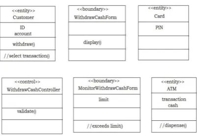
6.6
Assigning attributes and operations to
classes – VOPC Class Diagram
Figure 3: VOPC Class Diagram for Withdraw Cash use case
6.7
Snapshot of use-case metrics derived –
Metrics taken from [16]
6.8
Snapshot of class metrics derived –
Metrics taken from [16]
6.9
Snapshot of Traceability Tree
7.
CONCLUSION
This work is focused more on demonstration of use case analysis rather than documentation of an actual project. Implementing TraceCases has also helped understand about traceability and the issues in its implementation, viz.,
Having just the right degree of granularity is important in a project.
Managing and updating traceability links is a tedious process if done manually.
Experience and training is required for writing and modelling use cases that can be successfully used in analysis and design. Care should be taken to avoid functionally decomposing use cases, over analyzing use case and analysis models, adding the right amount of details in use cases and not mixing analysis and design decisions.[17]
Metrics were also derived based on the use-case model elements and analysis classes. These helped gain an insight into the project considered.
8.
LIMITATIONS OF EXISTING
SYSTEM
This technique relies on scenarios to find nouns and hence, entity classes and attributes. Scenarios are not always available. It is difficult to exhaustively specify scenarios, especially in the beginning of a project. Detailed and accurate scenarios may not be available for all use cases.
For assigning responsibilities to classes based on the scenarios, the internal behaviour of the system needs to be described in use case specifications (scenarios). This internal behaviour is normally not specified in detail while writing scenarios.
International Journal of Computer Applications (0975 – 8887) Volume 90 – No 11, March 2014
Architectural mechanisms can be incorporated into TraceCases[20].
Weights can automatically be assigned to use cases based on scenarios by counting the number of transactions.
Responsibilities can be automatically assigned to classes based on the data they contain and the GRASP principles by Larman.
Traceability Identifiers can be used to test exception scenarios and alternative flows through a use case. They can be associated with test cases.
Two PSP Design Templates are being used, viz., Operational Specification Template and Functional Specification Template. Two remaining design templates, viz., Logic Specification Template and State Specification Template can be used in the future.
10.
REFERENCES
[1] Ahmed F., Campbell P., Jaffar A., Alkobaisi S. Learning & Personality Types: A Case Study of a Software Design Course published in Journal of Information Technology Education: Volume 9, 2010
[2] O. Coltell, P. Ortiz, A. Fabregat, E. Barrera, G. Xaler, M. Arregui. STRATEGY TO INTRODUCE UML AND RUP IN SOFTWARE ENGINEERING UNDERGRADUATE COURSES in the proceedings of INTED 2009.
[3] Jan Bergandy. “Teaching Software Engineering with Rational Unified Process® (RUP)” in proceedings of the ASEE New England Section 2006 Annual Conference.
[4] Gary Evans. Getting from use cases to code Part 1: Use case Analysis. (http://www-106.ibm.com/developerworks/rational/library/5383. html)
[5] PSP Scripts, Forms, Templates, and Standards. Carnegie Mellon University.
[6] Zhao J. Robust Object Oriented Systems Analysis. Dunstan Thomas Consulting.
[7] Spence I., Probasco L. Traceability Strategies for Managing Requirements with Use Case. Rational Software White Paper. TP166, 2000
[8] Webb D.R., Lipkin I., Shraer E.S., Designing in UML with the Team Software Process. CrossTalk: The Journal of Defense Software Engineering, March 2006.
[9] Liu D. Automating Transition from Use Cases to Class Model. A Thesis.
[10]Marathe P. Auto-generation of Use case Controllers. A Thesis. 1-1-2010.
[11]Tobias Krumbein, Thomas Kudrass. Rule-Based Generation of XML Schemas from UML Class Diagrams.
[12]Anthony J. H. Simons, Carlos Alberto Fernandez y Fernandez. Using Alloy to model-check visual design notations.
[13]http://epf.eclipse.org/wikis/abrd/core.tech.common. extend_supp/guidances/examples/uc_model_elabora tion_phase_70035F60.html
[14]http://epf.eclipse.org/wikis/openup/core.tech.comm on.extend_supp/guidances/examples/use_case_spec _CD5DD9B1.html
[15]Roggio R.F., Use Cases and Traceability: a Marriage for Improved Software Quality in Proceedings of the 16th annual NACCQ, Palmerston North, New Zealand, July, 2003.
[16]Kim H. Boldyreff. Developing Software Metrics Applicable to UML Models.
[17]Haumer P. Use Case-Based Software Development. IBM Rational Software.
[18]Westerheim H., Hanssen G.K. Extending the Rational Unified Process with a User Experience Discipline: a Case Study.
[19]Heumann J. User experience storyboards: Building better UIs with RUP, UML, and use cases published in Rational Edge, November 2003.