Performance Evaluation of Optimized Mobile IP Protocol
Vis-à-vis Bit Map Indexing Method
Amrit Ghosh
Assistant Professor, Electronics & Communication Engg.
Department Sir Padampat Singhania
University, Bhatewar Udaipur-313601, India
Prasun Chakrabarti
Associate Professor & HOD,Computer Science Engg. Department Sir Padampat Singhania
University, Bhatewar Udaipur-313601, India
Divya Bhatnagar
Assistant Professor, Computer Science Engg.Department Sir Padampat Singhania
University, Bhatewar Udaipur-313601, India
ABSTRACT
Mobile IP is such a protocol that provides the mobility support in the Internet. However, even with some proposed optimization techniques, there are still some drawbacks in regard to improve its performance. In this paper, a novel bit map indexing scheme has been represented to improve the performance. In this scheme, each mobile node can be shifting to a foreign network which is associated with the Register Buffer by using bit map indexing method. A sender sends packets to the receiver which is stored further in the Register Buffer so that it could reach to the destination. During handoff, a mobile node could decide whether to move its buffer and report the handoff to the home agent, or, simply report the handoff to the buffer. In this way, this scheme optimizes the burden on the home agent so that the total cost of message delivery and mobility management can be mitigated. To evaluate the performance of the proposed scheme, a performance model has been developed, considering two way models for mobile nodes along with a proposed iterative algorithm for deriving a minimal point where the minimum cost parameter has been achieved. The results show that the new scheme can enable Mobile IP route optimization with proper handoff extension, irrespective of number of packets received during each shift.
General Terms
Data Transfer and performance evaluation for Mobile IPv4 by novel Bit Map Indexing Method along with algorithm.
Keywords
The Register Buffer, performance evaluation, Mobile IP, optimized output and simulation.
1.
INTRODUCTION
The tremendous growth of wireless communication technology along with sophisticated devices introduces a growing demand for mobile computing. The challenge for Mobile IP is to provide effortless network access without any disruption with the wired network. It was already investigated that the Internet Protocol (IP) for mobile internetworking would lead to Mobile IP [1].
In this protocol, each mobile node is assigned with an IP address called home address in its home network. When it is
away from the home network, its address is assigned by a foreign agent in the foreign network via care of address. Home agent maintains a network binding between the home address and the care-of address in a binding cache. Mobile nodes have been destined with regular IP routing to its home network where they have been captured by the home agent [2]. The home agent then tunnels these packets to the foreign agent which, in turn, sends them to the final destination. However, Mobile IP suffers from triangle routing problem. Therefore, Mobile IP route optimization [3] proposed to find out the solution for this aspect. Any particular node that has been going to communicate with a mobile node maintains a binding cache. When the home agent intercepts a packet for the mobile node outside the home network, may send a binding update message to the sender. It has been informing about the mobile node’s current care-of address. The sender then updates its binding cache and tunnels any packets intended for the mobile node directly to its care-of address. Smooth handoff helps foreign agents to make use of binding updates to reduce packet loss during handoff procedure. The mobile node may enquire about the binding update which has a relation to the previous foreign agent. The previous foreign agent then updates its binding cache and thereafter, resends any packets intended for the mobile node to its new care-of address. There are still several performance problems that have to be addressed.
handoffs in a low speed WAN. The proposed novel register based buffer scheme by using bit map indexing method has been used to solve the performance problems stated above. Each mobile node (which is shifting itself to a foreign network),would be associated with the Register Buffer at the destination. The sender sends the packets to the receiver’s buffer, which in turn sends them to the destination. There remains a choice for reporting about the handoff, either to the home agent or simply to the Register Buffer.
In order to characterize the performance of the proposed scheme, a performance model has been developed along with a cost dependant parameter function. An iterative algorithm has also been proposed for deriving aminimal point where the cost function reaches its optimized value. Mobile IP route optimization with smooth handoff procedure is used as a remarkable development in our performance comparison. The performance results show that the proposed scheme could meet the desirable result. This paper is organized as follows: The second section has been describing the proposed register-based buffer scheme using bit map indexing method. The third section has been presenting the performance evaluation with results. For the fourth Section (which is based on the performance model), the performance of the proposed scheme has been compared with that of the existed scheme. The fifth section has been presenting a review of the related work. The final section has been providing the concluding remarks.
2.
THE REGISTER BUFFER BASED
SCHEME
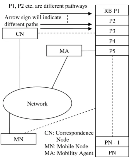
Throughout this paper, both home agent and foreign agent would be called as mobility agent [2, 3]. All the modifications have been done for mobility agent without any changes to the existing system for a mobile node. Every mobile node is associated with the Register Buffer, which would be a type of database located at a mobility agent.As shown in figure 1, if a sender wants to send a packet to a mobile node, it simply sends the packet to the receiver’s the Register Buffer in the first step. Later, the receiver receives the packet from its Register Buffer which could be stated as second step. (There is only one exception that a packet would not be sent to the Register Buffer but delivered directly to the receiver [4]. This has been happening when the mobile node situates in the home network and the sender need not maintain the mobility binding for the receiver).
Initially, the Register Buffer is situating in its own network as per arrangement. When the mobile node realizes that it has entered a new foreign network, it receives an Agent Advertisement [5] message from a new foreign agent. Then it would send to registration message to old foreign agent where its Register Buffer has been situating. The old foreign agent then decides whether to move the Register Buffer to the new foreign agent or not. There are two important factors considered for this case. The first factor is the distance between the old and new foreign agent, while the second factor is the load on communication traffic. Thus, the number of packets have to be received at the time of residing in its new foreign agent is a key factor. If the distance between the old and new foreign agents is long, and if at the same time, the mobile node has expected to receive many packets, then it would be costly to forward all these packets to the new address. In this case, it has been a better to move the Register Buffer closer to the mobile node so as to achieve a more optimal route as per solution point of view [6]. On the other hand, if the mobile node seldom receives packets, or, the distance between the foreign agents is too short, it is much more economical and worthy to leave the Register Buffer.
This has been done, in order to reduce the overhead for registration. The distance between the foreign agents may be obtained from the routing table of the old foreign agent if it uses routing protocols, e.g. OSPF [7].
[image:2.595.317.539.442.712.2]In this proposed work, a pair of variables a, and b is used to determine the Register Buffer’s migration, or, shifting. If either the distance between the foreign agents exceeds a, or, the load on the communication traffic exceeds b, the Register Buffer would migrate, or, shift to the new foreign agent. Otherwise, the Register Buffer would stay at the old foreign agent. Handoff is also being subdivided as handoff1, i.e., the handoff without the Register Buffer and handoff2, i.e., the handoff with the Register Buffer. Apart from the Register Buffer, another new database called as an address table has to be associated with each mobility agent. Each entry in the address table would be associated with six variables, and they could be stated as follows: mobile node’s home address, address of the Register Buffer, an identification mark, the variable pair, an indicator to the Register Buffer, and the mobile node’s care of address. The identification mark is used to indicate whether the Register Buffer’s address has been outdated or not. Table 1 is being used to give an example of address table where the first entry shows a remote Register Buffer in another mobility agent and the second entry shows the Register Buffer is associated with handoff1, which can also be termed as local. The proposed scheme also used to suggest operations of shifting, or, migration and packet forwarding. This proposed scheme, at first, would be working as per figure 1. Here, the data packets have been forwarded to the Register Buffer, which is connected with the receiver, i.e. mobile node and mobility agent by N number of paths. In the proposed scheme, all the paths may not be used for data packet transmission and thus as per figure 1, some of the slots in the Register Buffer could be empty (it should be noted that, each path is having its own slot in the Register Buffer).
Figure 1: Register Buffer based scheme RB P1
P2 P3 P4 P5
PN PN - 1 Arrow sign will indicate
different paths
P1, P2 etc. are different pathways
CN
MA
Network
MN
CN: Correspondence Node
Table 1. An example of the Address Table
Home Addr
RB’s Addr.
Identification
No. V.P. In COA
Addr C Remote True Null Null Null
Addr D Local True (a,
b) An In1
Addr E
Here, as per table 1, Addr is the abbreviated form of Address, RB is the Register Buffer, V.P. is the Variable Pair, In is the label of Indicator to the Register Buffer, In1 is an Indicator and COA is Care-of-Address.
The data packets would be forwarded in synchronous way of transmission through different pathways, which is shown by arrow marks. Some of the pathways, which have not been used, may not be free for synchronous data packet transmission as those paths would be loaded with excessive traffic. As per figure 1, RB has to be marked as the Register Buffer, which in turn, is associated with mobile node and mobility agent. Migration, or, shifting, as well as, packet forwarding would be two such important issues, which would be related with synchronous data packet transmission. Here, the latency for data traffic may be avoided, if the channel capacity for respective pathways would be increased more.
2.1 Migration Technique
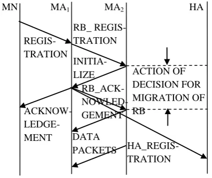
[image:3.595.61.273.554.731.2]When the new mobility agent, MA1 receives an advertisement, the mobile node, i.e. MN would decide that as now it has crossed the boundary of the old network; it would move to a new one to initialize the registration process. At first, it would use the gratuitous address resolution protocol [8] to update the address resolution protocol caches of the nodes in the foreign network, so that they may associate mobile node’s link layer address with mobile node’s home address. After that, it would send a registration message to MA1. The featured information contained in this registration message is going to be the address of the mobility agent MAm where the Register Buffer, RB, is currently situating. The message exchanging process is shown in figure 2.
Figure 2: Message exchanging in registration by Register Buffer
Here, it has been proposed that, for N number of pathways, (i.e. for PN), M number of pathways are not in use due to excessive traffic and hence (N – M) number of pathways (i.e. PN-M) would be used for data packet transmission in synchronous way. After receiving the registration message, MA1 would extract the address of MAm from the message, and sends a registration message to MAm, which may be termed as “RB_REGISTRATION”. After receiving the registration message, this is termed as a buffer message, known as “RB_REGISTRATION” message, MAm would decide whether to move the RB to the new location of mobility agent according to the variable pair in the address table. In the case when RB would not migrate, MAm simply updates the care-of address of MN to the mobility agent, MA. If it would not be the case, then the action taken would be taken as follows:
1. The identification number of the corresponding entry is being set in such a way so that the Register Buffer would no longer be used; and
2. An initialization message is being sent to the new mobility agent with a request to create a new Register Buffer RB for MN.
The identification number and initialization message are going to be very important factors with respect to the new allocation of the mobility agent. Both of these parameters would decide the smoothness of handoff as well as the fluency in data packet communication between correspondent node (i.e. CN) and Mobile Node (i.e. MN). The Register Buffer registration process would be responsible for the evolution of acknowledgement from the Register Buffer itself, as well as, the home agent registration process. This scheme has been proposed for ideal case when all the paths would be available for data packet communication and real – time cases when some of the paths would not be used in internet.
After receiving the “INITIALIZATION” message, MA1 creates a new allocation for the Register Buffer as RB’ and adds an entry to its address table. Then it records this newly created allocation for the Register Buffer. Based on the current circumstances, it would characterize a new variable pair for the mobile node. It also sends three messages, which are as follows.
1. An “ACKNOWLEDGEMENT” message to MN, has been providing the information regarding the new address of the Register Buffer i.e. RB;
2. An “RB_ACKNOWLEDGEMENT” message to MAm, has been conveying it about the creation of a new allocation of the Register Buffer i.e. RB’; and
3. An “HA_REGISTRATION” message to the home agent by registering the new address of the Register Buffer for bit map indexing method.
Upon receiving the “RB_ACKNOWLEDGEMENT” mes- sage, MAm performs the following actions:
1. By updating the address of the Register Buffer in the address table for the new allocation of Register Buffer i.e. RB’;
2. By setting the identification number to be true;
RB_ REGIS-TRATION
REGIS-TRATION
INITIA-LIZE
ACKNOW-LEDGE- MENT
RB_ACK- NOWLED-GEMENT
DATA
PACKETS HA_REGIS-TRATION
ACTION OF DECISION FOR MIGRATION OF RB
MA2
MA1
3. Communicate every data packet, which has to be buffered in RB to RB’ (i.e., the new allocation of RB);
4. Inform about the new address of the Register Buffer to the senders of the buffered packets in RB by sending messages; 5. When all the data packets have been communicated, the Register Buffer would be deconstructed and set null to the last three positions in the address table, i.e., the variable pair, the indicator to the Register Buffer and the care-of address; and 6. Upon receiving the “HA_REGISTRATION” message, in accordance, home agent would update the address of the Register Buffer.
2.2 Packet Forwarding
When one correspondent node, (i.e. CN) wants to send a data packet to a mobile node, (i.e. MN), it would first check its binding cache to see, whether or not, the address of the mobile node is cached in the local environment. If it is positive, then it would send the data packet, which is associated with regular IP, would be communicated to the mobile node’s home address. If the packet arrives at the home network, the home agent (i.e. HA) would intercept the packet. When an MA (i.e. mobility agent) would receive a packet, which is destined to the mobile node, (i.e. MN), it would perform some actions according to the algorithm, as stated below.
Algorithm: 1.First of all, the address resolution protocol (i.e. ARP) cache is checked for mobile node (i.e. MN).
2. If it exists, then the packet is communicated to the network. 3. If it does not exist, then the address table is checked for mobile node (i.e. MN).
4. For non-existence of ARP cache, the location of the Register Buffer should be checked.
5. If the Register Buffer is situated locally, the packet would be inserted into the Register Buffer.
But, if the Register Buffer is situated at remote distance, then a tunnel would be formed for all the data packets, which would be up to that particular site (which is equal to the remote distance) and there after it would send a message of updating, which could be termed as “PRESENT SITUATION” message to the sender by informing it about the current address of the Register Buffer.
For a data packet in the RB, that is forwarded to MN, (i.e. mobile node), the mobility agent (i.e. MAm) would at first check the valid identification number. If it is stated as a false one, the packet forwarding would be suspended and then it would be entirely depending on the migration, or, shift process to communicate the data packet to the new Register Buffer. If the identification number is going to be as a true one, it would tunnel the packet to the care-of address of mobile node.
2.3 Performance Modelling
In this section, a performance model has been developed which is used for characterization of the proposed scheme by presenting a system model for a mobile network, especially, for a mobile node, which is adopted in many existing studies such as [9] and [10]. Based on this, the cost functions for the proposed as well as the existed benchmark schemes have been
developed.The cost function includes both the cost for signal transmission and the cost for data packet delivery.
2.3.1 Performance model
This model has been assuming that the coverage area of the mobile network is partitioned into different subcategory which is termed as a unit.A unit is defined as the coverage area for a mobility agent that has the capability of exchanging data packets with mobile nodes directly through the air interface. A mobility agent serves only one unit and units need not overlap with each other. It is noted that, in this situation the Mobile Node could also obtain a new COA, (i.e. Care–of-address) by contacting the Dynamic Host Configuration Protocol (i.e. DHCP) or Point-to-Point Protocol (i.e. PPP) [11, 12]. Due to the fact that the packet would arrive at the Mobile Node, which has been addressed to its home address, it would be processed properly by the upper protocol layers, e.g., TCP. In data communication, the delay usually refers to the end-to-end delay, which would range from the sender to the receiver. The end-to-end delay has a significant effect on the perceived quality of data, and if it is not the same in both directions, then it is termed as an asymmetric links. It is the sum of the processing, queuing, transmission and propagation delays.The relation between the end-to-end delay and data quality is also optimum as per the proposed scheme. Mobile IP in 802.11b WLANs runs over the UDP protocol that does not offer reliable delivery of the data packets. During periods of congestion or interference, the packets may be lost. The data application has to deal with and has to tolerate packet losses up to a very small value. It could deal with 1.5% losses without loss concealment and up to 2 % using loss concealment techniques [13].
Throughput is supposed to be expressed in Kbps. For throughput calculation mean values have been taken for some particular time duration. From the graphical representation of throughput vs. time, the handoff time could be calculated also. In a mechanism, it has proposed to solve the Mobile IPv4 inter-domain handover issues, which is an enhanced extension to the route optimization technique in which it would deliver an enhanced performance at all handover rates. The inter-domain handover delay and the loss of IP packets during handover are optimized. This was done by storing the incoming IP packets at the previous Foreign Agent, until the moment a new Care-of Address assigned for the roaming Mobile Node is authenticated. After that moment, the IP packets have been communicated to the new Foreign Agent. In order to analyze and compare the performance of this mechanism, simulation experiments were done. These experiments were performed in the basic Mobile IP [MIPv4] [14]. The used performance measure is the TCP end-to-end delay. Furthermore, a better performance could also be achieved by this scheme under increased handover registration delays. Good quality of service means providing satisfactory experience to the end users. Data traffic is mostly affected by packet loss and is more resilient to delay. Jitter is the packet inter-arrival statistical variation introduced by the IP network links. The performance modeling could be evaluated by keeping all these parameter aspect for calculation.
The home network is host to a home agent that is mandatory support for Mobile IP. In the beginning UDP packets would suffer extended packet loss and high inter-packet delays due to link congestion in WLAN network. At time=30 sec, the first ftp would start with the transmission of registration request to Home Agent. At time=35 sec, the second ftp would commence with the key attributes of communication such as, packet loss, throughput & inter-packet delay that are measured in test scenario along with the Register Buffer using different pathway. In Mobile IP, a mobile node used to issue a new registration request only when it is performing a Mobile IP hand-off. This has been initiated as a response to a change in its link-layer status, such as during link layer hand-off. During Mobile IP hand-offs a mobile node is unable to send or receive packets and is therefore said to suffer network service disruption.
[image:5.595.49.271.476.548.2]However, in the investigated scenario the mobile node is neither moving, nor does it perform a link-layer hand-off. As such, during the initiation of the registration request no service disruption is suffered and for this no packet loss could be accredited to it. As it is seen, the primary reason for packet loss in the investigated scenario is network congestion [15]. Prior to the registration, the network would suffer significant congestion that caused UDP packets to be buffered in queues. It is noted that the behavior is caused by the Linux kernel and its queue management. It is shown that in the early stages of the communication, no packet loss is present. This is due to the fact that all network queues are initially empty and reached maximum capacity at some point in the communication. At time 30sec, extended packet loss is witnessed due to the transmission by the mobile node of a registration request. Initially, the UDP flow suffers increased delays due to buffering but manages to accelerate shortly after relieving of the home agent’s buffers. Table 2 is showing 5 sessions of ftp.
Table 2. For 5sessions of ftp
In the beginning of the experiment, the TCP flows would reach equilibrium by sharing the available resources and managing similar throughput performances in WLAN network scenario. The following results show the performance of Data packets over WLAN network capacity. The test scenario is given here as follows.
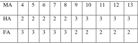
HA2 refers to BS1 and HA3 refers to BS2. BS stands for AP and BS1 Stands for AP1.Again, MA refers to 4, MA1 refers to 5, MA2 refers to 6, MA3 refers to 7, MA4 refers to 8, MA5 refers to 9, MA6 refers to 10, MA7 refers to 11, MA8 refers to 12 and MA9 refers to 13. Here, MA moves towards FA at 40 sec. and goes back to HA at 100 sec. Again, MA7 moves towards FA at 50 sec. and goes back to HA at 120 sec. Again MA3 moves towards FA at 70 sec. and goes back to FA at 140 sec. 0.0). Here, ftp – 1 starts at 30.0 seconds, ftp -2 starts at 35.0 seconds, ftp – 3 starts at 40.0 seconds, ftp – 4 starts at 45.0 seconds and ftp – 5 starts at 50.0 seconds .For 1st Session (i.e. ftp – 1), MA: tcp1 is Source and MA9: sink1 is Sink. For
2nd Session (i.e. ftp – 2), MA1: tcp2 is Source and MA8: sink2 is Sink. For 3rd session (i.e. ftp – 3), MA2: tcp3 is Source and MA7: sink3 is Sink. For 4th Session (i.e. ftp – 4), MA3: tcp4 is Source and MA6: sink4 is Sink. For 5th Session (i.e. ftp – 5), MA4: tcp5 is Source and MA5: sink5 is Sink. Here, HA represents home agent, AP represents access point, BS represents base station, MA represents mobility agent.
2.3.3 Usefulness of VLAN in simulation
environment
In order to simulate the roaming over a wireless environment within a closed laboratory situation, following experimental set up is made.
As per requirement, VLAN was configured in the beginning. The term VLAN is used to refer to a collection of devices that communicate as if they were on the same physical LAN. Any set of ports (including all ports on the switch) is considered as a VLAN. Here, the segments are defined by flexible user groups with command-line interfaces.
1. VLANs help to control traffic; 2. VLANs provide extra security; and
3. VLANs ease the change & movement of devices.
Switching between the VLANs, which are moving from the range of one VLAN into the other, is taking place automatically by taking an IP from the DHCP address pool and proper slot of the Register Buffer by choosing correct pathway for data packet stream. But, packet forwarding hampers when Mobile Node’s point of attachment changes from one VLAN domain to other. This is because of inherent characteristics of IP routing. As IP does not support mobility, change of access point means invalid IP address to the previous session. At this point implementation of Mobile IP protocol needs to support user roaming across wireless domains maintaining the previous session. The controller switch should have the ability to route between VLANs to give a correct picture of the inter – VLAN traffic in a mobile environment. It would need special arrangements and Mobile IP software without which roaming could not be Solaris Mobile IP implementation technique of SUN Laboratory is being used for this purpose. Mobile IP works with multiple data link technologies so a computer could move between a wireless LAN and a wired LAN while maintaining its IP address and all existing connections and the protocol would not require any changes to network applications or static host.
2.3.4 The SUN Solaris implementation of Mobile
IP
The Mobility Agent software has two components. 1. User level program, called mipagent; and 2. Dynamically loadable kernel module, called vtunl.
Mipagent would implement both Home Agent and Foreign Agent functionality as described in RFC 2002. It would respond to agent solicitations and registration messages. It would also perform periodic tasks such as sending agent advertisements and aging mobility bindings with visitor entries. IP–in–IP encapsulation and decapsulation could be MA 4 5 6 7 8 9 10 11 12 13
HA 2 2 2 2 2 3 3 3 3 3
implemented inside the kernel by the vtunl module. Mipagent uses special iotcl commands to control the behavior of vtunl. Like the Mobility Agent, Mobile Node software has two components also.
1. User level program, called mipmn; and
2. Vtunl Mipmn that implements the responsible MN. For sending agent solicitations, monitoring agent advertisements, initiating registration requests, processing replies and aging registrations. Vtunl could be used for decapsulation of IP-in-IP packets when the mobile node has registered a Co-located Care-of Address. This software should be run on portable computers with roaming facilities that would wish to maintain a fixed IP address irrespective of their current location.
2.3.5 Set up Procedure
1. In the beginning, Mobile IP Software would be loaded under root in Linux platform.
2. Mipmn.conf and mipfilter.conf files would be copied under /home/adu while mipagent.conf file is copied under /etc. 3. Proper configuration would be required for mipagent.conf and mipmn.conf.
4. Proper configuration would be required for all slots of the Register Buffer by choosing correct pathway.
(a) Under VLAN 1: Computer A as a Mobile Node (MN) with IP: 184.168.1.102, Subnet Mask: 255.255.255.0. Home Agent Address for MN: 184.168.1.100 (it is configured as Mipagent). Another Linux machine on VLAN 1: Computer B, configured for mipagent whose IP address is: 184.168.1.103 and Mobile Node address is set as 184.168.1.100.
(b) Agent under VLAN 2: One Linux machine under VLAN2 is configured for mipagent for which IP address: 184.168.2.100, Mobile Node Address: 184.168.2.101.
2.3.6 Experimentation
1. For the test procedure, at first computer A has run for mipmn (command. / mipmn) keeping the entire agent silent. MN sends registration request (solicitation) and in response would get destination unreachable, i.e. eth0 = U.
2. Home agent on VLAN 1 has run with. / mipagent command. It would start sending advertisement, could get ICMP packets from MN and MN on VLAN 1 instantly detects it as HA (i.e., Home Agent) and eth0 = H. At the same time slots of the Register Buffer is also formatted. For ICMP data packet communication, correct pathway is being also chosen with proper correction in flow mobility.
3. Mipagent on VLAN 2 now runs and starts sending advertisement, since no MN does not get any ICMP packets from any mobile node’s solicitation.
4. Now, the MN under VLAN 1 would move to VLAN 2, it could detect the agent advertisement by the mipagent on VLAN 2, but rejected the agent.
5. One more mipagent on VLAN 1 having IP 184.168.1.103 has run as mipagent with a mobile node address 184.168.1.100. It would start sending agent advertisement message as a FA (i.e. Foreign Agent).
6. By that time mobile node under VLAN 1 could move to its home network VLAN 1. It would start receiving FA advertisement and could send response, eth0 = F.
7. When this FA is off, MN immediately attached to it’s HA on VLAN 1 and eth0 = H.
2.3.7 Experimental observation for registration
process and ping operation under Mobile IP
scenario with the proper alignment of the Register
Buffer and correct pathway respectively
At first, Registration request (solicitation) has been sent by the MN to HA and in response gets eth0 = U (i.e. response gets destination unreachable). It has happened when all other agents are silent. When HA on VLAN 1 runs with ./mipagent command, it starts sending advertisement, would get ICMP packets from MN and MN on VLAN 1 instantly detects it as HA (i.e., Home Agent) and eth0 = H. One more Mipagent on VLAN 1 having IP 184.168.1.103 runs as mipagent with a Mobile Node address 184.168.1.100. It starts sending Agent Advertisement Message as a FA (i.e. Foreign Agent). By that time Mobile Node under VLAN 1 could move to its Home Network VLAN 1. It would start receiving FA advertisement and sends response, eth0 = F. Throughout the process, the correct alignment for the Register Buffer and respective pathways would be maintained properly.
All MNtrace results could be shown which implies Registration process.
---- Satur September 15 15:14:44 2012 (3141.151838) ---- MN sent registration request to 184.168.1.101, [MN 184.168.1.102, HA 184.168.1.101, COA 184.168.1.101], [Lifetime 50 sec, ID 0000000000: 0x70d75a52].
Registration sent by MN is:
0180 0032 c0a8 0166 c0a8 0165 c0a8 0165 0000 0000 70d7 5a52 2014 0000 0101 2e63 c720 1ee5 c1fb e06d 0342 a42e de80
eth0=F eth0=F eth0=F eth0=F eth0=F eth0=F eth0=F ---- 15:44:54 1178289894 756086 ---- sent registration request ---- Satur September 15Wed July 25 15:16:14 2012 (3171.050924) ----
MN sent registration request to 184.168.1.101, [MN 184.168.1.102, HA 184.168.1.101, COA 184.168.1.101], [Lifetime 50 sec, ID 0000000000: 0x4848e76f].
Registration sent by MN is:
08bc 2eda 85cc fa5f 436e fb67 6151
eth0=F eth0=F. Deleting registration request would be sent to FA, when it is suddenly off 184.168.1.101 (COA 184.168.1 .101, HA 184.168.1.101). Here, by Ping Operation under Mobile IP Scenario, we are able to get the statistics for number of data packets transmitted, number of data packets received, percentage of packet loss, total time.
Some ping operations are shown under Mobile IP Scenario. [root@localhost root]# ping 184.168.1.101
PING 184.168.1.101 (184.168.1.101) 56(84) bytes of data. 64 bytes from 184.168.1.101: icmp_seq=1 ttl=64 time=0.390 ms. From 184.168.1.104: icmp_seq=1 Redirect Host (New nexthop: 184.168.1.101). From 184.168.1.104: icmp_seq=2 Redirect Host (New nexthop: 184.168.1.101). 64 bytes from 184.168.1.101: icmp_seq=2 ttl=64 time=0.233 ms. From 184.168.1.104: icmp_seq=3 Redirect Host (New nexthop: 184.168.1.101). 64 bytes from 184.168.1.101: icmp_seq=3 ttl=64 time=0.225 ms. From 184.168.1.104: icmp_seq=4 Redirect Host (New nexthop: 184.168.1.101). 64 bytes from 184.168.1.101: icmp_seq=4 ttl=64 time=0.231 ms. From 184.168.1.104: icmp_seq=5 Redirect Host (New nexthop: 184.168.1.101). 64 bytes from 184.168.1.101: icmp_seq=5 ttl=64 time=0.230 ms. From 184.168.1.104: icmp_seq=6 Redirect Host (New nexthop: 184.168.1.101). 64 bytes from 184.168.1.101: icmp_seq=6 ttl=64 time=0.235 ms. 64 bytes from 184.168.1.101: icmp_seq=7 ttl=64 time=0.221 ms. From 184.168.1.104: icmp_seq=8 Redirect Host (New nexthop: 184.168.1.101) 64 bytes from 184.168.1.101: icmp_seq=8 ttl=64 time=0.227 ms. 64 bytes from 184.168.1.101: icmp_seq=9 ttl=64 time=0.213 ms. 64 bytes from 184.168.1.101: icmp_seq=10 ttl=64 time=0.205 ms. From 184.168.1.104: icmp_seq=11 Redirect Host (New nexthop: 184.168.1.101). 64 bytes from 184.168.1.101: icmp_seq=11 ttl=64 time=0.211 ms. 64 bytes from 184.168.1.101: icmp_seq=12 ttl=64 time=0.194 ms. 64 bytes from 184.168.1.101: icmp_seq=13 ttl=64 time=0.190 ms. 64 bytes from 184.168.1.101: icmp_seq=14 ttl=64 time=0.186 ms. 64 bytes from 184.168.1.101: icmp_seq=15 ttl=64 time=0.178 ms. 64 bytes from 184.168.1.101: icmp_seq=16 ttl=64 time=0.174 ms. From 184.168.1.104: icmp_seq=17 Redirect Host (New nexthop: 184.168.1.101). 64 bytes from 184.168.1.101: icmp_seq=17 ttl=64 time=0.181 ms. 64 bytes from 184.168.1.101: icmp_seq=18 ttl=64 time=0.164 ms. 64 bytes from 184.168.1.101: icmp_seq=19 ttl=64 time=0.161 ms. 64 bytes from 184.168.1.101: icmp_seq=20 ttl=64 time=0.253 ms. 64 bytes from 184.168.1.101: icmp_seq=21 ttl=64 time=0.271 ms. 64 bytes from 184.168.1.101: icmp_seq=22 ttl=64 time=0.249 ms. 64 bytes from 184.168.1.101: icmp_seq=23 ttl=64 time=0.259 ms. 64 bytes from 184.168.1.101: icmp_seq=24 ttl=64 time=0.255 ms. 64 bytes from 184.168.1.101: icmp_seq=25 ttl=64 time=0.211 ms. 64 bytes from 184.168.1.101: icmp_seq=26 ttl=64 time=0.245 ms. 64 bytes from 184.168.1.101: icmp_seq=27 ttl=64 time=0.240 ms. 64 bytes from 184.168.1.101: icmp_seq=28 ttl=64 time=0.235 ms. 64 bytes from 184.168.1.101: icmp_seq=29 ttl=64 time=0.231 ms. 64 bytes from 184.168.1.101: icmp_seq=30 ttl=64 time=0.226 ms. 64 bytes from 184.168.1.101: icmp_seq=31 ttl=64 time=0.221 ms. 64 bytes from 184.168.1.101: icmp_seq=32 ttl=64 time=0.215 ms. 64 bytes from 184.168.1.101: icmp_seq=33 ttl=64 time=0.214 ms. 64 bytes from 184.168.1.101: icmp_seq=34 ttl=64 time=0.207 ms. 64 bytes from
184.168.1.101: icmp_seq=35 ttl=64 time=0.197 ms. 64 bytes from 184.168.1.101: icmp_seq=36 ttl=64 time=0.184 ms. 64 bytes from 184.168.1.101: icmp_seq=37 ttl=64 time=0.191 ms. 64 bytes from 184.168.1.101: icmp_seq=38 ttl=64 time=0.188 ms. 64 bytes from 184.168.1.101: icmp_seq=39 ttl=64 time=0.178 ms. 64 bytes from 184.168.1.101: icmp_seq=40 ttl=64 time=0.175 ms. 64 bytes from 184.168.1.101: icmp_seq=41 ttl=64 time=0.169 ms. 64 bytes from 184.168.1.101: icmp_seq=42 ttl=64 time=0.166 ms. 64 bytes from 184.168.1.101: icmp_seq=43 ttl=64 time=0.285 ms. 64 bytes from 184.168.1.101: icmp_seq=44 ttl=64 time=0.238 ms. 64 bytes from 184.168.1.101: icmp_seq=45 ttl=64 time=0.273 ms. 64 bytes from 184.168.1.101: icmp_seq=46 ttl=64 time=0.268 ms. 64 bytes from 184.168.1.101: icmp_seq=47 ttl=64 time=0.264 ms. 64 bytes from 184.168.1.101: icmp_seq=48 ttl=64 time=0.257 ms. 64 bytes from 184.168.1.101: icmp_seq=49 ttl=64 time=0.254 ms. 64 bytes from 184.168.1.101: icmp_seq=50 ttl=64 time=0.248 ms. 64 bytes from 184.168.1.101: icmp_seq=51 ttl=64 time=0.237 ms. 64 bytes from 184.168.1.101: icmp_seq=52 ttl=64 time=0.237 ms. 64 bytes from 184.168.1.101: icmp_seq=53 ttl=64 time=0.232 ms. 64 bytes from 184.168.1.101: icmp_seq=54 ttl=64 time=0.228 ms. 64 bytes from 184.168.1.101: icmp_seq=55 ttl=64 time=0.219 ms. 64 bytes from 184.168.1.101: icmp_seq=56 ttl=64 time=0.218 ms. 64 bytes from 184.168.1.101: icmp_seq=57 ttl=64 time=0.177 ms.
2.3.8 Cost function of proposed scheme under
performance model
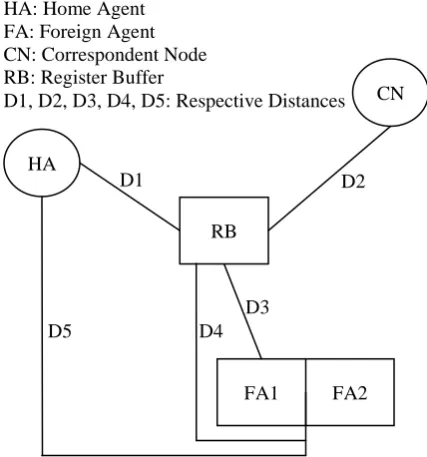
Figure 3: Network Scenario about MN’s migration in proposed scheme
As per the above figure (i.e. figure 3), distances could be shown between respective agents, e.g. HA and FA along with CN and RB. The above figure would show mobile node’s migration in our proposed scheme. As per the figure, two foreign agents are adjacent to each allocation of the Register Buffer and respective mobile nodes.
HA: Home Agent FA: Foreign Agent CN: Correspondent Node RB: Register Buffer
D1, D2, D3, D4, D5: Respective Distances
HA
CN
RB
FA2 FA1
D1 D2
[image:7.595.323.537.404.633.2]2.3.9 Derivation of cost for data packet
communication in the form of a signal
Letus assume that, the Register Buffer would migrate at the mobile node’s Nth migration, it is ascertained that N-1 handoff local site and one handoff at home location. Thus the cost for data packet communication which can be termed as Cost Data Packet Communication. Figure 3 is showing the network scenario about MN’s registration as per our proposed scheme.
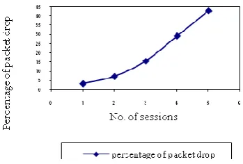
3. PERFORMANCE EVALUATION
[image:8.595.325.500.113.231.2]Here, the performance of the proposed scheme has been compared with that of the existing benchmark scheme in which route optimization would be shown with smooth process of handoff after a through investigation done by simulation. From the observations, it is clearly seen that, the average delay of UDP packets (in ms) for our proposed scheme, is much less compared to the existed benchmark scheme. The graphical representation of the previous benchmark scheme is shown in figure 4, whereas the graphical representation as per our existed scheme is shown in figure 5. As per figure 5, the graph is obtained by simulation.
Figure 4: Average delay of UDP packets vs. No. of sessions for 50m/s speed as per existed benchmark
scheme
Figure 5: Average delay of UDP packets vs. No. of sessions for 50 m/s speed as per proposed scheme
[image:8.595.65.238.491.587.2]Table 4. Comparison in observation Table for UDP packets drop vs. no. of sessions for speed of mobile host as 20m/s in the existing benchmark scheme
[image:9.595.49.231.123.431.2]and proposed scheme
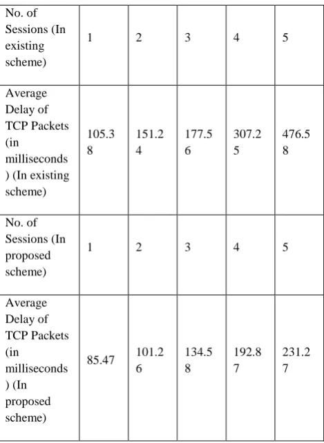
Table 5. Comparison in observation Table for average delay of TCP packets vs. no. of sessions for
mobile host as 50m/s for existing scheme
No. of Sessions (In existing scheme)
1 2 3 4 5
Percentage of UDP Packets drop (In existing scheme)
7.68 7.82 8.13 8.29 8.58
No. of Sessions (In proposed scheme)
1 2 3 4 5
Percentage of UDP Packets drop (In proposed scheme)
5.32 5.69 6.25 7.21 7.95
No. of Sessions (In existing scheme)
1 2 3 4 5
Average Delay of TCP Packets (in
milliseconds ) (In existing scheme)
105.3 8
151.2 4
177.5 6
307.2 5
476.5 8
No. of Sessions (In proposed scheme)
1 2 3 4 5
Average Delay of TCP Packets (in
milliseconds ) (In proposed scheme)
85.47 101.2 6
134.5 8
192.8 7
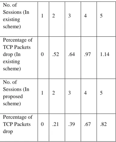
Table 6. Comparison in observation Table for TCP packets drop vs. no. of sessions for speed as 20m/s
for the mobile host in the existed benchmark scheme and the proposed scheme
Table7. Comparison in handoff time of TCP packets (in sec.) vs. Speed of Mobile host in existed benchmark scheme and proposed scheme
4. RELATED WORKS
As per [16], a hierarchy in mobility management scheme has been proposed in which foreign agents could be organized in accordance to a particular order according to the topology based on region(s). As per the proposed scheme, it would reduce handoff latency, percentage of packet drop(s) as well as load balancing on the inter – network. Location of the foreign agent can be changed as per adaptability which depends on the alignment and hierarchy of the Register Buffer, as per the proposed scheme. The reliability of [16] can be enhanced in [17] by adding buffer to all the foreign agents so that the packet loss during the migration of a mobile node could be reduced remarkably but not optimized, which would be possible by using simulation as per the proposed scheme.
5. CONCLUSION
In this paper a novel, bit map indexing method has been proposed by the Register Buffer technique for the purpose of improvement and optimization of the Mobile IP’s performance. The performance evaluation would provide a pleasant result which demonstrates the utility and usefulness of the Register Buffer. Further, the dynamic choice was made for the Register Buffer in order to get the best and optimized performance of Mobile IP with respect to its parameters.
6. REFERENCES
[1]. Andreoli, G., Blefari-Melazzi, N., Listanti, M., Palermo, M. Mobility management in IP networks providing real-time services, Proc., Annual International Conference on Universal Personal Communications; 1996, p. 774–777. [2] Perkins, C., IP Mobility Support. RFC 2002. Network
Working Group; October 1996.
[3] Perkins, C., Johnson, D., Route Optimization in Mobile IP. , November 1997; IETF Draft.
[4] Calhoun, Rubens, DIAMETER, November 1998; Internet draft, draft-calhoun-diameter-07.txt.
[5] Perkins, C., IP Mobility Support for IPv4. RFC 3220, January 2002.
[6] Jacobs, S., Mobile IP Key Based Authentication, March 1999; Internet draft, draft-jacobs-mobileip-pki-auth-02.txt.
[7] Moy., J., OSPF Version 2. RFC 1274. Network Working Group; October 1996.
[8] Postel, J., Multi - LAN Address Resolution. RFC 925, October 1984.
[9] Wang, Y., Chen, W., J. Ho. Performance Analysis of Mobile IP Extended with Routing Agents, Proc., 2nd European IASTED International Conference on Parallel and distributed Systems; July 1998.
[10] Akyildiz, I., F., Ho, J., S., M., Lin, Y., B. Movement – Based Location Update and Selective Paging for PCS Networks. IEEE / ACM Trans. Networking. August 1996; vol. (4): p. 629–638.
No. of Sessions (In existing scheme)
1 2 3 4 5
Percentage of TCP Packets drop (In existing scheme)
0 .52 .64 .97 1.14
No. of Sessions (In proposed scheme)
1 2 3 4 5
Percentage of TCP Packets drop
0 .21 .39 .67 .82 Speed (in
m/s) (In existing scheme)
10 20 30 40 50
Handoff time (in sec.) (In existing scheme)
68 70 72 74 69
Speed (in m/s) (In proposed scheme)
10 20 30 40 50
Handoff time (in sec.) (In proposed scheme)
[image:10.595.49.243.436.672.2][11] Hiller, T., (editor) 3G Wireless Data Provider Using Mobile IP and AAA, March 1999; Internet draft, draft-hiller-3gwireless-00.txt.
[12] Simpson, W., (editor), The Point-to-Point protocol (PPP). RFC1661, July1994.
[13] Teo, W., T., Li, Y., Mobile IP extension for Private Internet Support (MPN), 1999; Internet draft, draft-teoyli-mobileip-mvpn-02.txt.
[14] Geiger, R., L., Solomon, J., D., Crisler, K., J., Wireless Network Extension Using Mobile IP. IEEE Micro. 1997; Vol. (17), No. 6, p. 63-68.
[15] Zao, J., K., Condell, M., Use of IPSec in Mobile IP, November 1997; Internet draft, draft-ietf-mobileip-ipsec-use-00.txt.
[16] Caceres, R., Padmanabhan, V., N., Fast and Scalable Handoffs for Wireless Internetworks, Proc., Second Annual International Conference on Mobile computing and Networking; Rye. New York, United states: November 1996, p. 56-66.