28
Improved Performance of Wind-Driven Isolated
Induction Generators by Six-phase Operation
S. Sasikumar
Assistant Professor
Department of Electrical Engineering Annamalai University, Annamalainagar
Tamilnadu – 608002, India
S. Singaravelu
Associate Professor
Department of Electrical Engineering Annamalai University, Annamalainagar
Tamilnadu – 608002, India
ABSTRACT
This paper describes a new, generalized and efficient steady-state model for the performance analysis of isolated six-phase induction generators. The mathematical model is formed directly from the equivalent circuit of six-phase induction generator by nodal admittance method. The proposed model is very simple which completely avoids lengthy derivations of non linear equations. The model results in matrix form so that inclusion or elimination of any equivalent circuit elements can be easily achieved. Also, this model is flexible to find any combination of unknown quantities of the equivalent circuit. The matrix equation is solved by genetic algorithm to determine the steady-state performance of isolated six-phase induction generator (ISPIG). To validate the improvement of performance by six-phase operation, the experimental and theoretical results were compared with three-phase operation. In addition, the winding diagram of the six-phase / three-phase induction generator which is used as a prototype model for the experimental study is also presented.
Keywords
Six-phase induction generator, Steady-state analysis, Genetic algorithm and Nodal admittance method.
1.
INTRODUCTION
There has been a huge increase in energy demand during the last few decades, which has accelerated the depletion of the world fossil fuel supplies. Thus, the use of renewable energy sources becomes essential and therefore, the study of self-excited induction generator (SEIG) has regained importance as it is particularly suitable [1-3] for wind and small hydro power plants. Due to the power rating increase of drives and high reliability requirements, research on multi-phase machines has followed a path of spectacular increase recently, and new techniques for the control of the multi-phase machines have been successfully developed [4-6]. The generator schemes presented in [7-9] were based on dual stator and asymmetrical six-phase induction generator. In all the cases, the output is not true six-phase. In this paper, modeling and analysis of six-phase induction generator (SPIG) with symmetrical phase displacement of 60○ electrical between the six stator windings [10] is presented.
In this paper, a novel and simplified mathematical model of SPIG in matrix form is developed using nodal admittance method. In this model, the nodal admittance matrix can be formed directly from the equivalent circuit of SPIG by nodal admittance method based on inspection. The advantage of the proposed model is that any equivalent circuit elements can be easily included or eliminated.
For the laboratory set up, the necessary stator terminals of the induction generator (IG) were taken outside so that the same machine can be utilized as six-phase as well as three-phase generator. To validate the improvement of performance by six-phase over three-phase operation, the experimental and theoretical results were compared. The values obtained by the quantitative analysis coincided with the experimental results, which validates the proposed model and solution technique. The winding diagram of the six-phase/three-phase induction generator which is used as a prototype model for the experimental study is also presented.
2.
PROPOSED MODEL
The formulation of a suitable mathematical model is the first step in the analysis of a six-phase induction generator (SPIG). Therefore, a mathematical model of a SPIG using nodal admittance method is proposed.
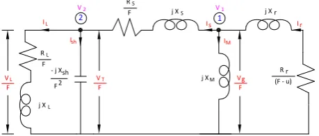
The per phase equivalent circuit of the SPIG with two nodes is shown in Fig. 1. Since the six stator windings are displaced symmetrically by 60○ electrical, it is possible to use the per phase equivalent circuit for six-phase induction generator. The equivalent circuit is valid for any per unit speed ʋ. The various elements of equivalent circuit are given below.
Zr = Rr / (F - υ) +j Xr; ZM = j XM;
ZS = Rs / F + j Xs; Zsh = - j Xsh / F 2
;
ZL = RL / F + j XL;
The branch admittances are:
Yr = 1/Zr; YM = 1/ZM; YS = 1/ZS; Ysh = 1/Zsh; YL = 1/ZL;
The matrix equation based on nodal admittance method for the equivalent circuit can be expressed as
[Y] [V] = [IS] (1)
j X R
(F - u) F
2
L
F
L
IL 2 1
F
VL j XM
j XS j X r
RS
F
- j Xsh R r
F Vg
I r Is
F VT
V2 V1
[image:1.595.316.546.423.521.2]Ish IM
Where [Y] is the nodal admittance matrix, [V] is the node voltage matrix, and [IS] is the source current matrix.
The [Y] matrix can be formulated directly from the equivalent circuit (Fig. 1) using nodal admittance method based on inspection [11] as
Yr + YM + YS - YS
- YS Ysh + YL + YS
where
Yii = ∑ Admittance of the branches connected to i th
node Yij = - ∑ Admittance of the branches connected between ith node and jth node
Since, the equivalent circuit does not contain any current sources, [IS] = [0] and hence Eq. (1) is reduced as
[Y] [V] = 0 (3)
For successful voltage build up, [V] ≠ 0 and therefore from Eq. (3), [Y] should be a singular matrix i.e., det [Y] = 0. Therefore to obtain required parameters which results det [Y] = 0, genetic algorithm based approach is implemented.
3.
GENETIC ALGORITHM BASED
PERFORMANCE EVALUATION OF
SPIG
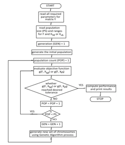
Application of genetic algorithm [12] to obtain det[Y] = 0, which provides solution for unknown quantities, is illustrated in Fig. 2. The objective function whose value is to be minimized is given by Eq. (4).
g (F, XM or Xsh) = abs{real(det[Y])} + abs{imag(det[Y])} (4)
In many optimization problems to obtain initial estimates suitably, certain trials may be required. However, in the present problem of the ISPIG, it is easy to give the range for the unknown variables F and XM or Xsh because in well-designed self-excited induction generators, it is known that the slip {(F − υ)/F} is small and operation of the machine is only in the saturated region of the magnetization
characteristics. So, the ranges for F can be given as 0.8 to 0.999 times the value of υ and for XMas 25% to 100% of critical magnetizing reactance XMO. Similarly for Xsh, the same range 25% to 100% of CMAX can be used, where CMAX is the maximum capacitance required under any conditions. Thus, starting from such initial estimates, the final value of F and XM or Xsh is obtained through GA.
The air gap voltage Vg / F can be determined from the magnetization characteristics corresponding to XM, as described in Section 4. Once the air gap voltage is calculated, the equivalent circuit (Fig.1) can be completely solved to determine the steady-state performance of ISPIG.
4.
EXPERIMENTAL SET UP AND
MACHINE PARAMETERS
To test the validity of the proposed method of analysis, and to investigate the performance characteristics of SPIG, a laboratory squirrel cage induction machine was utilized as a basis. The test machine consists of two three-phase stator winding sets namely winding set ABC (stator-1) and winding set XYZ (stator-2). The necessary stator terminals of both winding sets were taken outside such that it can be utilized as six-phase as well as three-phase induction generators by suitable end connections (Appendix). The schematic diagram of SPIG with capacitor bank, six-phase to three-phase transformer [13] and load is shown in Fig. 3.
The ratings of the test machine whose photograph is shown in Fig. 4 are as follows: 4-pole, star connected, 2.2kW, 230V, 5A, 50Hz. The per unit stator resistance (Rs), stator leakage reactance (Xs), rotor resistance (Rr) and rotor leakage reactance (Xr) of six-phase and three-phase induction generator are 0.09123, 0.047, 0.0137, 0.047 and 0.18246, 0.094, 0.0137, 0.047 respectively.
Magnetization characteristics of the machine play a vital role in the analysis of induction generator. The magnetization curve of the induction generator can be determined by conducting synchronous speed test [14, 15]. The measured per unit variations of Vg/F with XM for six-phase induction (2)
[Y] =
START read all required
parameters for matrix Y read population size (PS) and ranges
for F and X or XM sh
generation (GEN) = 1 generate the initial population
population count (POP) = 1 evaluate objective function g(F, X ) or g(F, X )M sh
whether g(F, X ) or g(F, X )M sh reached desired
tolerance POP = POP + 1
is POP < PS GEN = GEN + 1 generate new set of chromosomes
using Genetic Algorithm process
compute performance and print results
STOP YES NO
YES
[image:2.595.329.529.358.460.2]NO
Fig. 2: Flow chart for minimization of the objective function using genetic algorithm (GA).
Prime Mover
A Y C
X
B Z
A Y C X
Z B
B Primay Side Secondary Side
Shunt Capacitor Bank
Y R
L O A D
Six phase-to-three phase Transformer 1:1 Six Phase Cage
Induction Generator
[image:2.595.64.271.419.659.2]Fig. 3: Schematic diagram of the induction generator system employing a ISPIG.
[image:2.595.357.507.583.709.2]30 generator are given by Eq. (5) and (6) and for three-phase
induction generator are given by Eq. (7) and (8) respectively.
For six-phase induction generator:
Vg/F = 1.21 – 0.44 XM, XM < 0.91 (5) Vg/F = 2.66 − 1.94 XM, XM ≥ 0.91 (6)
For three-phase induction generator:
Vg/F = 1.21 − 0.22 XM, XM < 1.82 (7) Vg/F = 2.66 − 0.97 XM, XM ≥ 1.82 (8)
5.
RESULTS AND DISCUSSION
The following steady-state performances of ISPIG and comparative analysis are discussed.
Steady-state performance analysis of ISPIG under pure resistive load.
Steady-state performance analysis of ISPIG under resistive-inductive load.
Comparative steady-state performance of ISPIG over isolated three-phase induction generator under pure resistive and resistive-inductive load.
5.1
Steady-state performance analysis of
ISPIG under pure resistive load
The steady-state analysis with magnetizing reactance (XM) and frequency (F) as unknowns for obtaining performance characteristics of the machine for fixed value of shunt capacitance and varying load is presented. To consider pure resistive load, the inductive load reactance (XL) is made zero in the ZL element of the equivalent circuit.
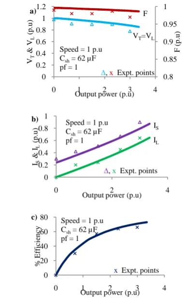
The ISPIG is excited with shunt capacitance of 62µF (corresponding to rated terminal voltage at no load) and the steady-state performance of ISPIG under varying resistive load is analyzed. The analytical and experimental variation of terminal voltage, load voltage and frequency with output power are shown in Fig. 5a. From this, it is observed that the load voltage and frequency decrease with increase in output power. The full load variation of load voltage is about 14.8% and frequency is 1%.
The experimental and computed variation of stator current and load current with output power are given in Fig. 5b and it is observed that stator current and load current are increasing with increase in output power but they are within the rated values. The variation of percentage efficiency with output power is shown in Fig. 5c. It is observed that the maximum efficiency is 73% at full load.
5.2
Steady-state performance analysis of
ISPIG under resistive-inductive load
[image:3.595.328.539.360.696.2]The ISPIG is excited with shunt capacitance of 62 µF and the steady-state performance of ISPIG under varying resistive-inductive (R-L) load at a lagging power factor of 0.8 is analyzed. Fig. 6a shows the load characteristics of the ISPIG, indicating the variation of terminal voltage, load voltage and frequency with output power for fixed value of shunt capacitance at rated speed of 1.0 p.u. The full load variation
Fig. 5: Variation of: (a) Terminal voltage, load voltage & frequency, (b) Stator current & load current, and (c) % Efficiency with output power of ISPIG subjected to
pure resistive load.
0.8 0.85 0.9 0.95 1 0 0.2 0.4 0.6 0.8 1 1.2
0 1 2 3 4
F ( p .u ) VT & V L (p .u )
Output power (p.u) Speed = 1 p.u Csh= 62 µF
pf = 1
∆,x Expt. points VT=VL
F a) 0 0.2 0.4 0.6 0.8 1
0 2 4
IS & IL (p .u )
Output power (p.u) Speed = 1 p.u
Csh= 62 µF
pf = 1
∆,x Expt. points IS IL b) 0 20 40 60 80
0 1 2 3 4
% Ef fi ci en cy
Output power (p.u) Speed = 1 p.u
Csh= 62 µF
pf = 1
x Expt. points
[image:3.595.60.259.390.698.2]c)
Fig. 6: Variation of: (a) Terminal voltage, load voltage & frequency, (b) Stator current & load current, and (c)
% Efficiency with output power of ISPIG subjected to resistive-inductive load at 0.8 pf.
0.8 0.85 0.9 0.95 1 0 0.2 0.4 0.6 0.8 1 1.2
0 0.5 1 1.5 2 2.5
F ( p .u ) VT & V L (p .u )
Output power (p.u) F
VT=VL
∆, xExpt. points Speed = 1 p.u
Csh= 62 µF
pf = 0.8
a) 0 0.1 0.2 0.3 0.4 0.5 0.6
0 1 2 3
IS & IL (p .u )
Output power (p.u) IS
IL
∆, xExpt. points Speed = 1 p.u
Csh= 62 µF
pf = 0.8
b) 0 20 40 60 80 100
0 1 2 3
% Ef fi ci en cy
Output power (p.u)
xExpt. points Speed = 1 p.u
Csh= 62 µF
pf = 0.8
of load voltage is about 22% and frequency is 0.6%.
The analytical and experimental variation of stator current and load current are shown in Fig. 6b. It can be noted the currents are within the rated value. Fig. 6c shows the variation of percentage efficiency with output power and in this case, the maximum efficiency is found to be 77%.
5.3
Comparative steady-state performance
of ISPIG over isolated three-phase
induction generator under pure resistive
and resistive-inductive load
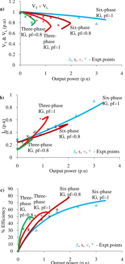
The comparative steady-state performance characteristics of isolated six-phase induction generator over isolated three-phase induction generator under pure resistive and resistive-inductive load are shown in Fig. 7a – 7c. It is observed that the voltage regulation, power handling capacity and efficiency
of isolated six-phase induction generator are far better than isolated three-phase induction generator.
6.
CONCLUSION
In this paper, a novel and generalized mathematical model based on nodal admittance method for the steady-state analysis of ISPIG is presented. The proposed method is simple and completely avoids the long, tedious analytical derivation of several equations. Also, proposed matrix equations can be easily modified to include or eliminate any equivalent circuit elements of ISPIG. Good agreement between the computed and experimental results is obtained which in general, verifies the accuracy of the proposed model and solution technique. The steady-state characteristics of ISPIG and isolated three-phase induction generator were observed and their performances were compared for different loading conditions. From the theoretical and experimental analysis, it is found that a promising improvement of the performance can be achieved in the case of six-phase induction generator when compared to three-phase induction generator.
7.
ACKNOWLEDGEMENT
The authors gratefully acknowledge the support and facilities provided by the authorities of Annamalai University, Annamalainagar, Tamilnadu, India to carry out this research work.
8.
REFERENCES
[1] M. Canale, L. Fagiano, M. Milanese, KiteGen, A revolution in wind energy generation, Int. J. Energy 34 (2009) 355-361.
[2] S. Singaravelu, S. Velusami, Capacitive VAr requirements of wind driven self-excited induction generators, Energy Convers. and Management 48 (2007) 1367-1382.
[3] S. Velusami, S. Singaravelu, Steady state modeling and fuzzy logic based analysis of wind driven single phase induction generators, Int. J. Renew. Energy 32 (2007) 2386-2406.
[4] E. Levi, R. Bojoi, F. Profumo, S. Williamson, Multiphase induction motor drives – A technology status review, IET Electr. Power Appl. 1 (2007) 489-516.
[5] E. Levi, Multiphase electric machines for variable speed applications, IEEE Trans. on Ind. Electron. 55 (2008) 1893-1909.
[6] Singh, G.K., Senthil Kumar, A., and Saini, R.P. 2011. Performance analysis of a simple shunt and series compensated six-phase self-excited induction generator for stand-alone renewable energy generation. Energy Conversion and Management, 52: pp. 1688-1699.
[7] O. Ojo, I.E. Davidson, PWM-VSI inverter assisted stand-alone dual stator winding induction generator, IEEE Trans. on Energy Convers. 36 (2000) 1604-1611.
[8] D. Wang, W. Ma, F. Xiao, B. Zhang, D. Liu, A. Hu, A novel stand-alone dual stator winding induction generator with static excitation regulation, IEEE Trans. on Energy Convers. 20 (2005) 826-835.
[image:4.595.68.269.263.686.2][9] D. Basic, J.G. Zhu, G. Boardman, Transient performance study of a brushless doubly fed twin stator induction generator, IEEE Transactions on Energy Convers. 18 (2003) 400-408.
Fig. 7: Comparative performance evaluation of isolated six-phase induction generator (with Csh = 62µF) over
isolated three-phase induction generator (with Csh = 31µF) under 1p.u speed: Variation of (a) Terminal voltage & load voltage, (b) Stator current, and (c) % Efficiency with output power for pure resistive (pf=1)
and resistive-inductive (pf=0.8) load. 0
0.2 0.4 0.6 0.8 1 1.2
0 1 2 3 4
VT
&
V
L
(p
.u
)
Output power (p.u)
Six-phase IG, pf=1
Six-phase IG, pf=0.8
Three-phase IG, pf=1
∆, x, +, * - Expt.points Three-phase
IG, pf=0.8
a) VT= VL
0 0.2 0.4 0.6 0.8 1
0 1 2 3 4
IS
(p
.u
)
Output power (p.u)
Six-phase IG, pf=1
Six-phase IG, pf=0.8 Three-phase IG, pf=1
Three-phase
IG, pf=0.8 ∆, x, +, * - Expt.points
b)
0 10 20 30 40 50 60 70 80 90
0 1 2 3 4
%
Ef
fi
ci
en
cy
Output power (p.u)
Six-phase IG, pf=1 Six-phase
IG, pf=0.8
Three-phase IG, pf=1 Three-phase IG, pf=0.8
∆, x, +, * - Expt.points
32 [10] S.N. Vukosavic, M. Jones, E. Levi, J. Varga, Rotor flux
oriented control of a symmetrical six-phase induction machine, Electr. Power Syst. Res. 75 (2005) 142-152.
[11] M.E. Van Valkenburg, Network Analysis, Third Edition, Prentice Hall of India Pvt. Ltd., New Delhi, 1994.
[12] D.E. Goldberg, Genetic algorithm in search, optimisation, and machine learning, Pearson Education, New Delhi, 2001.
[13] William D. Roehr, Rectifier Applications Hand book, SCILLC, 2001.
[14] S. Singaravelu, S. Velusami, Generalized steady state modeling and analysis of three-phase self-excited induction generators, Int. J. of Emerg. Electr. Power Syst. 3 (2005) 1-31.
[15] S. Velusami, S. Singaravelu, Steady state modeling and analysis of single-phase self-excited induction generators, Electr. Power Compon. and Syst. 35 (2007) 63-79.
9.
APPENDIX
End connection for six-phase and three-phase modes of operation:
For six-phase induction generator: Join FA-FB-FC-FX-FY-FZ
For three-phase induction generator: Join FA-FX, FB-FY, FC-FZ and SX-SY-SZ
[image:5.595.61.536.240.442.2]SA SZ SB SX SC SY FA FZ FB FX FC FY