© 2018, IRJET | Impact Factor value: 6.171 | ISO 9001:2008 Certified Journal | Page 1033
Comparison between Manual calculation and Software calculation of
G+5 Building Using Staad pro
M.A. Qureshi
1,Nidhi Bhavsar
2, Pratiksha Chaudhari
3, Parth Panchal
4,
Siddharth Mistry
5, Ankit Makadia
61
Assistant Professor, Civil Engineering Department, FETR, Bardoli, Gujarat, India
2,3,4,5,6Students, Civil Engineering Department, FETR, Bardoli, Gujarat, India
---***---Abstract -
Earthquakes are known to produce one of the most destructive forces on earth. It has been seen that during past earthquakes many of the building were collapsed. Therefore, realistic method for analysis and design are required. Performance Based Design is the modern approach for earthquake resistant design. It is an attempt to predict the performance of buildings under expected seismic event. In this present study a G+5 multi-storeyed hospital building is analysed by seismic action situated at different zone. It involves the calculation of load and total Seismic weight of building from that the base shear is calculated in different zone.Key Words: Analysis and comparison, Earthquake
Behaviour, STAAD Pro, Base Shear
1. INTRODUCTION
Buildings constitute a part of the definition of civilizations, a way of life advanced by the people. The construction of buildings should be looked upon as a process responded to human requirements rather than as a product to be designed and built a great expense.
It is well known fact that users of any software for structural analysis and Design do not know whether the program is having any bugs or its correctness while using. Since any program developed may contain some error or bugs it is necessary for the users to check the model and analysis and design results manually.
Base shear is an estimate of the maximum expected lateral force that will occur due to seismic ground motion at the base of a structure.
Earthquake-resistant structures are structures designed to withstand earthquakes. While no structure can be entirely immune to damage from earthquakes, the goal of earthquake-resistant construction is to erect structures that fare better during seismic activity than their conventional counterparts.The main objectives of earthquake engineering are:
Forces the potential consequences of strong earthquakes on urban areas and civil infrastructure.
Design, construct and maintain structures to perform at earthquake exposure up to the expectations and in compliance with building codes
1.1 Objective
To compare the results of base shear by manual analysis and Staad
The input data while modelling the structures is correct.
The assumed and the input loads on the structure are in par with the actual condition of the structure.
The support condition considered are as per site condition.
1.2 Features of Staad pro
Quality Assurance
Broad Collection of design codes
Covers all aspects of structural engineering
Reports and Documentation
2. Methodology
Determination of design earthquake forces is computed by the following methods:
1. Equivalent static lateral method 2. Dynamic Analysis
In the first method, different partial safety factors are applied to dead, live, wind earthquake forces to arrive at the design ultimate load. In the IS: 456-2000 code, while considering earthquake effects, wind loads assuming that both severe wind and earthquake do not act simultaneously. The American and Australian code recommendations are similar but with different partial safety factors
.
© 2018, IRJET | Impact Factor value: 6.171 | ISO 9001:2008 Certified Journal | Page 1034
3. Load Calculation
Fig -1: AutoCAD Plan
I. Dead load
a) Floor Load
Slab Load
Self-weight of slab = 3.75 kN/m²
Floor finish = 1.5 kN/m²
Total Load = 5.25 kN/m²
Terrace Load
Self-weight of slab = 3.75 kN/m²
Floor finish + Water proofing = 1.5 kN/m²
Total Load = 6.95 kN/m²
b) Wall Load
External Wall of 230mm thick
Floor height = 4000 mm
Beam depth = 0.75 m
Total Load
[2 (4 – 0.75 – 0.75)6 + 2(4 – 0.15- 0.15)4] ×0.23 × 20
= 274.16 kN/m
Internal Wall of 115mm thick
Floor height = 4000 mm
Beam depth = 0.75 m
Total Load
[2 (4 – 0.75 – 0.75)6 + 2(4 – 0.15- 0.15)4] ×0.115 × 20 = 273.70 kN/m
c) Beam Load
Longitudinal beam
Self-weight of beam = 25*.75*.3
Total load
(6 × 5) × (4 – 0.75 -0.75) ×5.63 = 422.25 kN/m
Transverse Beam
Self-weight of beam = 25*.75*.3
Total load
(4×7) × (4 – 0.75 -0.75) ×5.63 = 583.27 kN/m
d) Column Load
Self-weight of Column = 25*.75*.75*35
Total Load = 492.18 kN/m
e) Parapet wall
Total load
= (24×2 + 16×2)
×0.115×20
= 184 KN
II. Live Load
Load on floor =24 × 16 × 0.5 ×4
= 768 KN
Weight of floor
[2016 + 422.25 +
583.27+2×445.51+2×444.76+2×984.36]+768
=7537.85 KN
Weight of roof
[2668.80 + 422.25 + 583.27 + 184 ×1 + 274.16 ( )
+ 273.70 ( ) + 492.18 × ] + 0
=5732.05 KN
Total Seismic weight of building
= Weight of roof + 4*Weight of floor
=
5732.05 + 4 × 7537.85© 2018, IRJET | Impact Factor value: 6.171 | ISO 9001:2008 Certified Journal | Page 1035 3.1 Seismic Load Calculation
Table-1: Base shear results (manual)
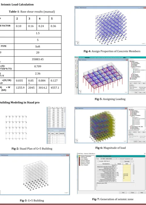
4. Building Modeling in Staad pro
Fig-2: Staad Plan of G+5 Building
Fig-3: G+5 Building
Fig-4: Assign Properties of Concrete Members
Fig-5: Assigning Loading
Fig-6: Magnitude of load
Fig-7: Generation of seismic zone
Zone 2 3 4 5
ZONE FACTOR 0.10 0.16 0.24 0.36
I 1.5
R 5
SOIL TYPE Soft
h (m) 20
W
(KN) 35883.45
Ta in (X) =0.075(h*0.75) (sec)
0.709
Sa/ g
=1.67/T 2.36
Ah =(ZI/2R)
(Sa/ g) 0.035 0.057 0.084 0.127 Vb (X) = W
[image:3.595.304.562.93.228.2]© 2018, IRJET | Impact Factor value: 6.171 | ISO 9001:2008 Certified Journal | Page 1036
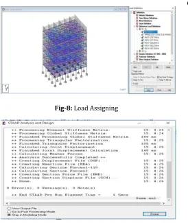
Fig-8: Load Assigning
Fig-9: Performance of Analysis
4.1 Base shear by Staad pro
Table-2: Base shear by Staad pro
5. Comparison between results of Base shear
Table-3: Base shear results
[image:4.595.35.310.84.410.2]6. RESULTS
Table-4: Comparison of base shear results
2.0 2.5 3.0 3.5 4.0 4.5 5.0 1000
1500 2000 2500 3000 3500 4000 4500 5000
1255.92
2045.36
3014.21
4557.19
1283.99
2079.34
3023.92
4637.61
Base
Shea
r (
KN)
Zone
Manual Staad
Fig-10: Zone v/s Base shear
7. CONCLUSION
The above checks can help to a greater extend and it makes sure that the user has modeled the structure with no mistake and further that there is no error in the input. After running the analysis also a simple check on the result can be made using the available formulae.
Manual analysis results are compared with the STAAD results and identified that the variation is at max 3%.
The value of base shear in Staad is more than the value of base shear by manual analysis.
Always better to know two or more than a single software so that a counter check can be made especially for a large and mega projects to avoid suspicious results and to continue his design with peace of mind.
8. REFERENCES
1. IS-875(PART-1) : 1987 Indian Standard CODE OF PRACTICE FOR DESIGN LOADS (OTHER THAN EARTHQUAKE) FOR BUILDINGS AND STRUCTURES Ah Actual weight of
building Lateral load Vb=(Ah*W)
0.127 18512.314 36516.594 4637.607
0.0848 18512.314 35659.394 3023.917
0.0565 18512.314 36802.537 2079.343
0.0353 18512.314 36373.863 1283.997
ZONE MANUAL STAAD PRO
2 1255.92 kN 1283.99 KN
3 2045.36 kN 2079.34 kN
4 3014.21 kN 3023.92 kN
5 4557.19 kN 4637.61 kN
Zone Manual Staad %Increment
2 1255.92 1283.99 2.18
3 2045.36 2079.34 1.63
4 3014.21 3023.92 0.32
[image:4.595.322.559.128.439.2]© 2018, IRJET | Impact Factor value: 6.171 | ISO 9001:2008 Certified Journal | Page 1037 PART 1 DEAD LOADS — UNIT WEIGHTS OF
BUILDING MATERIALS AND STORED MATERIALS. 2. IS-875(PART-2): 1987 Indian Standard CODE OF PRACTICE FOR DESIGN LOADS (OTHER THAN EARTHQUAKE) FOR BUILDINGS AND STRUCTURES PART 2 IMPOSED LOADS.