1
Digital Signature Scheme for Image
Kanchan K. Doke S. M Patil
Department of Information Technology Department of Information Technology
Mumbai University Mumbai University
ABSTRACT
Image authentication techniques have recently gained great attention due to its importance for a large number of multimedia applications. Digital images are increasingly transmitted over non-secure channels such as the Internet. Therefore, military, medical and quality control images must be protected against attempts to manipulate them; such manipulations could tamper the decisions based on these images. To protect the authenticity of multimedia images, several approaches have been proposed. These approaches include conventional cryptography, fragile and semi-fragile watermarking and digital signatures that are based on the image content. The aim of this paper is to present emerging technique for image authentication. It also introduces the new concept of image content authentication and discusses the most important requirements for an effective image authentication system design. Methods which are described provide strict or selective authentication, tamper detection, localization and reconstruction capabilities and robustness against different desired image processing operations.[1]
Keywords
cryptography, digital signature, wavelet, content authentication, structural feature.
1. INTRODUCTION
Normally, image data can allow for lossy representations with refined degradation. The information carried by image data is mostly retained even when the image has undergone reasonable levels of filtering, geometric distortion or noise corruption. Therefore bit-by-bit verification is no longer a suitable way to authenticate image data, and an image authentication tool that validates the content is more desired [2,3]. Content-based authentication is an efficient approach, which passes images as authentic when the content does not change. The work extending the digital signature scheme from data (fragile or hard) authentication (i.e. even a difference of 1 bit is not allowed) to content (semi-fragile or soft) authentication (i.e. some acceptable manipulations such as lossy compression need to be tolerated) may be traced back to.
For image authentication, it is desired that the verification method be able to resist content preserving modifications while being sensitive to content changing modifications. The introduction of 3G wireless communication systems, together with the invasive distribution of digital images and the growing concern on their originality triggers an emergent need of authenticating images received by unreliable channels, such as public Internet and wireless networks. To meet this need, a content-based image authentication scheme that is suitable for an insecure network and robust to transmission errors is proposed. The proposed scheme exploits the scalability of a structural digital signature in order to achieve a good trade off between security and image transfer for networked image applications.
2.LITERATURE REVIEW AND PRESENT
STATE OF ART
Methods of image content authentication can be categorized into either digital signature based or watermarking based. A digital
signature (or crypto-hash) is a set of extracted features, which captures the essence of image content in compact representation. It is stored as an extra file and later used for authentication. Signature based methods can work on both the integrity protection of the image and repudiation prevention of the sender. Watermarking, on the other hand, is an invasive method that really embeds a message into an image data and the hidden message is later extracted to verify the authenticity of image content. Watermark-based approaches only work for protecting the integrity of the image. The major difference between a watermark and a digital signature is that the embedding process of the former requires the content of the media to change. For image authentication, it is desired that the verification method be able to resist content preserving modifications while being sensitive to content changing modifications. Most previous efforts in content-based image authentication have concentrated on developing methods under the ideal assumption of reliable noise-free transport like extraction of structural information as digital signature [4] and the authentication signature is based on the invariance of the relationships between discrete cosine transform (DCT) coefficients [6] at the same position in separate blocks of an image. However, these methods do not work well when used to transmit images over the error-prone wireless channel. For example, any transmission bit error will render traditional authentication a failure. In addition, synchronization may become a problem for conventional security techniques in the case of packet loss. This would imply a significant increase of latency because of the need of retransmission and/or the bit overhead caused by forward-error-correction. However, requiring all bits to be received correctly overlooks the fact that many image applications can tolerate certain bit errors or data loss that are perceptually less important. It is clear that traditional authentication algorithms do not cope well with lossy networks and the loss-tolerant nature of the multimedia data.
The application of image authentication over wireless channels has deservedly attracted much attention since it requires not only careful design of the authentication methodology, but also appropriate selection of the set of channel codes for effective forward-error-correction. Recently, a number of good solutions have been proposed for authenticating the image data stream in the presence of random packet loss.
For example:
1.A novel mutual image-based authentication framework [13] has been presented. It consists in a challenge-response scheme based on visual password and image scrambling. The application window is divided into k grids, each made of h cells. During the pass image/s selection procedure the user has to correctly identify the k pass image/s among N images, randomly extracted from the JPEG2000 database. Similarly, during the detail selection one secret detail must be recognized for each pass image through the iterative zooming process. The visual password codes are transmitted step by step, minimizing the risk of sniffing. Whenever the server detects an authentication failure, the authentication process is not interrupted until the last step. Only then, the user is rejected and a notification policy is adopted.
2 datagram-oriented image/video transmission. A SARI image
embeds two kinds of information watermarks: authentication bits and recovery bits. The content-based watermark bits generated from a block set, which includes two blocks for extracting authentication bits and four blocks for generating recovery bits, are embedded into other blocks in the image. The locations of corrupted blocks are detected by the embedded authentication information, while the lost blocks in a SARI image are approximately recovered based on the recovery information.
2.Massage authentication code [15]:- A robust digital signature of image can be generated as follows. First, the image is partitioned and transformed into 8x8 blocks. Those blocks are further labelled as either T block or E block. We choose T blocks for extracting MACs and E blocks for watermarking. The selection and relations of T and E blocks can be specified by random seeds that are included in the digital signature. For each T block, we pick up its DC and 3 AC to generate MACs. These 4 coefficients are quantized by preset authentication strength matrix Q,. These 4 hits are then watermarked into its corresponding E blocks. We embed the watermark of T block by directly modifying some AC coefficients in E. A typical ratio of T and E blocks is 1: 8. Among 8 E blocks of a T block, we only embed the watermark into those 3 blocks with highest AC energy. A one-way crypt hash function such as MD5 or SHA-1 is applied to the MACs concatenated from all T blocks. In addition to these hash values, other auxiliary information includes the size of image, and the authentication strength matrix (Q,) is combined together and is encrypted using the sender's private key to obtain the crypto signature.
However, above methods are having high computational difficulties, so that their application may become critical in the case of mobile devices, where the signature scheme must be efficient enough to permit authentication on the fly without introducing delays. A choice has been made to develop a simple, yet valuable wireless image authentication scheme that enhances the state-of-the art schemes to improve robustness and security.
3.
DIGITAL
SIGNATURE
SCHEME
The major differences that differentiate the proposed scheme from existing state-of-the-art [14,15] approaches are:
(1) It works at a semi-fragile level, which means that some manipulations on the image will be considered acceptable; (2) More robustness – it can tolerate a range of attacks while accurately locating the tampered area – is achieved by exploiting the concept of structural digital signature (SDS);
(3) The integration of the SDS and key dependent parametric wavelet filters makes the scheme more efficient to security attacks;
(4) The ability to support efficient and accurate tamper localization in spite of information loss in large areas or high variant areas.
The major issue is to develop a signature based image authentication scheme, which tries to overcome the several constraints on security and the data transmission capability imposed by a wireless environment. The robustness of the generated scheme is achieved by employing the concept of structural features, whereas security is achieved by adopting a filter parameterization technique.
3.1Image signing procedure
In the image signing procedure as depicted in Fig.1given the image to be sent over the wireless channels. The system generates a digital signature by performing a signing process on the image in the following order:
1.Decompose the image using parameterized wavelet filters;
2.Extract the SDS;
3.Cryptographically generate the crypto signature by the image senders private key; and
4.Send the image and its associated crypto signature to the recipient. In consideration of robustness, no compression and coding is used, since they will cause error propagation.
Fig 1: Diagram of image signing procedure
3.1.1
Decompose
the
image
using
secrete
parameterized wavelet filter:
The generated image‟s signature is constructed in the wavelet domain. Wavelet transform is characterized by excellent energy compaction and de-correlation properties; hence, it is employed to effectively generate a compact representation that exploits the structure of the image [8,9]. Wavelets are also tolerant with respect to colour intensity shifts, and can capture both texture and shape information effectively. Further, wavelet transforms can generally be computed in linear time, thus allowing for fast algorithms. Most conventional wavelet-based image authentication schemes reported in the literature have three shortcomings [13–15]:
(1) Their security is questionable without protecting the coefficients used to construct the signature from malicious attacks;
(2) Low robustness to some content preserving attacks; and (3) High computational complexity.
To handle the above shortcomings, the concept of lifting based wavelet filter parameterization has been suggested as an effective method to improve the security and processing speed of the wavelet transform[16]. Given N parameter values –π ≤ αi ≤ π, o
≤ i ≤ N, the recursion
,
--- Eq. 1. can be used to determine the filter coefficients cNk , 0 ≤ k ≤ 2N +
2 and ck for k < 0 and k ≥ 2N + 2. The parameter values used for
construction and the resulting wavelet filter coefficients are kept secret. Consequently, the scheme decomposes the host image
Private key Encryption
Structural Signature Filter Parameterization Original
Image
Transmission of Image + Signature
Secret Wavelet Decomposition
Digital Signature Extraction
Crypto Signature
3 using a wavelet filter constructed with the above parameterization.
A wavelet transform based on secret filters can act as a security framework independent of the signing algorithm.
3.1.2 Generation of Structural signature:
The scheme uses the same SDS algorithm [4,11] with the employment of wavelet filter to increase security. In the wavelet domain of an image, the so-called joint (interscale) parent–child pairs exist. Each parent–child pair maps to a set of spatial pixels, which is of a non-fixed size and possesses certain contextual dependencies [8]. This dependency arises from the perceptually important features, for example, edges and textures as illustrated in Fig.2.
(a) (b)
Fig 2 : Structural signature
The basic concept of the SDS algorithm relies on the fact that the parent–child pairs with large magnitudes are not vulnerable to attacks, whereas those with smaller magnitudes tend to be easily attacked. Therefore one can use the larger pairs to indicate robustness (content-changing manipulations) and use smaller pairs to reflect fragility (content-preserving manipulations). The construction of an SDS is summarized as follows. Given a pre-determined threshold ∂, select each parent–child pair <p, c> with
||<p,c>|| ≥ ∂
the SDS array is recorded as
--- Eq. 2
where [i, j]is a child‟s coordinates of significant pairs in the parameterized wavelet domain, and λ is defined as
3.1.3
Generate Crypto Signature:
The symbols and their locations in the wavelet domain are encrypted by RSA algorithm. The RSA algorithm works as follow:
1. Select two lager prime numbers p & q such that p≠q 2. Calculate n=p*q and phi=(p-1)*(q-1)
3. Select „e‟ such that 1<e<phi and e is coprime to phi 4. Calculate d=e-1 mod phi
This process generate Public_key which is [e,n] and Private_key [d,n]. The private key is used at the sender side for the encryption. To sign the SDS, compute: S = Md(mod n), where M is symbol and its location. Generated signature is send to the recipient. The public key is published to the receiver, which is later used for decryption of received signature.
3.2Image authentication procedure
In the image authentication procedure shown in Fig 3, given corrupted images by transmission and their associated digital signatures, the proposed scheme authenticates both the integrity
and the source of the received image by applying the following process on the
Fig 3: Diagram of image authentication procedure
image in the following order: (1)perform content-adaptive error concealment, if some blocks are damaged; (2) extract the SDS of the received image using the same method used in image signing; (3) decrypt the signature by using the sender‟s public key (calculate v = se mod n); (4) perform a content authenticity verification procedure using both the decrypted signature and the extracted one to calculate the completeness of SDS (CoSDS) and declared that the received image is authentic or not; (5) the attacked areas are detected using an attack detector.
1.1.1
Error concealment:
In common wireless scenarios, the image is transmitted over the wireless channel block by block. Because of severe fading, entire image blocks can be lost. Therefore during the verification of image authenticity, error detection and concealment will be carried out. Error concealment techniques are usually applied by either using the contextual relationship of adjacent blocks [7,12]. An error concealment algorithm based on edge-directed filters is applied to achieve better visual quality. A summary of this algorithm is as follows. First, the damaged image blocks are detected by exploring the contextual information in images (e.g. edge continuity). The statistical characteristics of missing blocks are then estimated based on the types of their surrounding blocks. Finally, a directional interpolation strategy for error concealment is applied.
Error Concealment Scheme:
The error concealment scheme can be summarized as:
………..
Eq. 3
Where In+1 is the recovered image after the n+1iterations and I0 is the received image. “0” is concatenation operation of two
functions. F is edge directed filter in the spatial domain to remove artefacts around edges. W is Wavelet Transform, and W-1 is the inverse Wavelet Transform. C is a function that rectifies the recovered results, taking in information regarding which bit-planes are lost, and I0 as input.
Secret Filters Degraded
Image
Received Signature
Error Detection & Concealment Public key
Decryption
Structural Features Wavelet
Decomposition
Digital Signature Extraction
Content- based verification Crypto
Signature
4 In other words, the damaged image is firstly filtered using edge
directed filter F, and then transformed into WT domain (W). The recovered WT coefficients are then constrained to their statistical characteristics in WT domain by using function C. These recovered wavelet coefficients are then transformed into the image domain again (W-1) to get a valid image In+1. The constraint function C comprises the known WT coefficient values constraint function C1 and the WT statistical characteristics constraint function C2, That is, C = C1 ° C2.
3.2.1.1 Edge directed filter :
Anisotropic diffusion techniques have been widely used in image processing for its efficiency of smoothing the noisy images while preserving the sharp edges. When proper function is constructed in anisotropic diffusion, it can form direction diffusion or edge directed filter to remove the ring or ripple artefacts around edges of damaged images caused by errors in high frequency subbands.
Diffusion function :
The anisotropic diffusion is used as a direction diffusion operation, and design a new diffusion function for error concealment. Since we only aim to construct edge directed filter to remove the ring or ripple artefacts caused by errors, in our solution the diffusion function f(x) is:
…….. Eq. 4
where Γ is the N×N pixels block which the damaged pixel belongs to (N = 16, k=1 in this paper), and | I| is the magnitude of I . ΔI is the Laplacian of image I, which is a second order derivative of I.
3.2.1.2 Wavelet domain constraint functions :
Two WT domain constraint functions are applied in wavelet domain: known-value constraint function C1, and WT statistical constraint function C2 to rectify the recovered coefficients. After the damaged image is filtered by edge directed filter, the lose WT coefficients are recovered. However, the correctly received WT coefficients (denoted as Ф) may also be altered at the same time. We should discard these changes, with known-value constraint function:.…..
Eq. 5
…….. Eq.6
where
x0
is the original wavelet coefficients of
x
before
edge directed filtering.
1.1.2
Content authenticity verification:
3.2.2.1 Method (1):
The basic idea of this procedure is to use patterns to distinguish distortions by transmission errors from those of attacks, convert these patterns into rules, calculate the degree of authenticity and un-authenticity [17], and finally obtain the authentication results. The distortion of an attacked image is often concentrated on some content of interest (local distortion), whereas the distortion from transmission is much more randomly distributed over the whole image (global distortion). Furthermore, the attacked areas are more likely to be connected. Therefore the maximum size of the connected modification areas of acceptable manipulation is small, whereas that of the tampering operation is large. From the above
facts, given M, the difference map between the extracted SDS (feature vector) from the received image and the decrypted signature associated with the image, the degree of authenticity and un-authenticity is defined as
…….. Eq.7
where R1 is the degree of global or local distortions, and R1 and RL
2 are the degrees of acceptable manipulation size or tampering
operation size. R1 is computed by
…….. Eq. 8
Where X and Y are the number of differences in the histogram of horizontal and vertical projections of M, respectively; N is the total number of differences in M; and a and b are constants that are experimentally equal to 100 and 10, respectively, as used in [12]. RS2 and R
L
2 are defined as :
…….. Eq. 9
…….. Eq. 10
W
here m is the size of the maximum connected areas in M; L and S denote the large and small sizes, respectively; and σ2= (L-S)2 /8 * ln 2. Finally, if DY > DN, then the image is classified as authentic; otherwise, tampering areas are detected.3.2.2.2
Method (2):
The distortion of an attacked image is often concentrated on some content of interest (local distortion), whereas the distortion from transmission is much more randomly distributed over the whole image (global distortion). Furthermore, the attacked areas are more likely to be connected. Therefore the maximum size of the connected modification areas of acceptable manipulation is small, whereas that of the tampering operation is large. A summary of verification process [11] is as follows, first decomposed I‟(received image)by wavelet transform and calculate it‟s SDS (i.e SDS(I‟)). Then decrypt the received SDS(I).Compare their signature symbols to check the interscale relationship of pair by:
sym(<p,c>)=sym(<p‟,c‟>). ……….. Eq. 11
Finally calculate the completeness of the SDS(CoSDS) in I by:
CoSDS(I) = Sim(SDS(I), SDS(Ĩ))
=
……….. Eq. 12
A larger CoSDS means the suspect image is reliable; otherwise, it means has been maliciously tampered with.
3.2.3
Attack location:
5 operations are used to compute connected areas and remove the
isolated blocks and little connected areas. Then the difference map (M) is masked by the union of the SDS and image features. The masking operation can refine the detected areas by concentrating these areas around the objects in the attacked image. Those areas in M which do not belong to an object are removed, which may be a false alarm of some noise or acceptable image manipulations. Such false alarms can be further reduced by removing isolated detected blocks.
4.ADVANTAGES
1. It works at a semi-fragile level, which means that some manipulations on the image will be considered acceptable. 2. More robustness – it can tolerate a range of attacks while
accurately locating the tampered area – is achieved by exploiting the concept of structural digital signature (SDS). 3. The integration of the SDS and wavelet filters makes the
scheme more efficient to security attacks.
4. The proposed scheme generates only one fixed-length digital signature per image regardless of the image size and the packet loss during transmission.
5. The ability to support efficient and accurate tamper localization in spite of information loss in large areas or high variant areas.
5.APPLICATIONS
Displaying sample products via mobile terminals in m-commerce, sending critical medical images for remote diagnosis and consultation, transmitting portraits of criminal suspects from law enforcement headquarter to the police officers‟ mobile devices, intelligence satellites sending reconnaissance images of battlefields, and transmission of surveillance video to the mobile terminals.
6.SIMULATION RESULTS AND
DISCUSSIONS
This section evaluates the proposed scheme by testing its security, robustness against transmission errors, robustness against some acceptable manipulations and ability to distinguish tampered areas. All experiments wereconducted with a number of classic benchmark images including the traditional girlface and Monalisa,etc.
Experiment 1 (resistance to attacks):
Results on girlface.bmp are shown in Fig. 4 to demonstrate the ability of the proposed scheme to localize the tampered content of the attacked image. The presented scheme shows excellent ability to detect tampering, even in the presence of multiple tampered areas. It can be concluded that the proposed scheme is more practical for content-based authentication, since it has a good performance at distinguishing malicious content modification from common content-preserving image processing.
(a)
(b) (c)
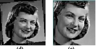
(d) (e)
Fig 4: Sample authentication results for ‘girlface.bmp’: (a) Original image, (b) Changed 8x8 block from the original image, (c) Authentication result of (b), (d)Authentication result of rotated (50) image, (e) Authentication result of cropped (20%) image
Table 1: Authentication result and CoSDS of ‘girlface.bmp’
To test the robustness of the proposed scheme against several acceptable manipulations, experiments are conducted by mounting a variety of attacks.Table 1tabulates the authentication defined as Authentic/ Unauthentic across several different (allowable) geometric distortions and the completeness of a structural digital signature was consistently very high for incidental manipulations when σ>=128. This indicates that our method can tolerate common incidental modifications very well. Experiment 2: The same procedure is applied on „monalisa.jpg‟ image whose result is shown next. Fig.5 (a) is the original image. Fig. 5 (b) shows the image whose contents are changed and its authentication. Table 2 shows the authentication result values of DoA and CoSDS.
(a) (b) (c)
(d) (e)
Fig 5: Sample authentication results for ‘monalisa.jpg’ : (a) Original image, (b) Changed 8x8 block from the original image, (c) Authentication result of (b), (d)Authentication result of rotated (50) image, (e) Authentication result of cropped (20%) image
Attacks
Method 1
(Authentic/
Unauthentic)
Method 2
CoSDS
Changing 8x8
block
Unauthentic
0.992063
[image:5.595.304.459.72.152.2] [image:5.595.311.543.236.322.2] [image:5.595.303.529.483.671.2]6
Table 2: Authentication result and CoSDS of ‘monalisa.jpg’
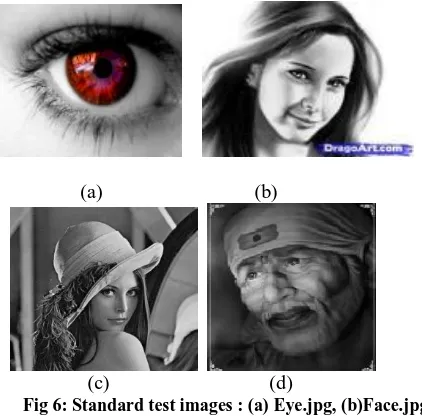
Experiment 3: The algorithm is evaluated on a number of standard test images which are shown in Fig. 6. Their authentication results are shown in table 3 and 4.
(a)
(b)
[image:6.595.59.270.245.453.2]
(c)
(d)
Fig 6: Standard test images : (a) Eye.jpg, (b)Face.jpg, (c)Lena.bmp,(d)Sai.jpg
Table 3: Authentication result on different images by Method 1
Image Name
Normal image
Changing 8x8 block
Rotating (50) Cropping (20%) Eye.
png
Authentic Unauthenti c
Unauthentic Unauthentic
Face. jpg
Authentic Unauthenti c
Unauthentic Unauthentic
Lena. bmp
Authentic Unauthenti c
Unauthentic Unauthentic
Sai. jpg
Authentic Unauthenti c
Unauthentic Unauthentic
Table 4: Authentication result on different images by Method2
Image Name
Normal image
Changing 8x8 block
Rotating (50)
Cropping (20%)
Eye.png 1 0.981763 0.714286 0.702128
Face.jpg 1 0.9923 0.626564 0.692012
Lena.bmp 1 0.992793 0.652252 0.844504
Sai.jpg 1 0.991471 0.520256 0.733475
7. REFERENCES
[1] S. M Saad “Design of robust and secure digital signature scheme for image authentication over wireless channels”. IET Inf. Secure., 2009, Vol. 3, Iss. 1, pp. 1–8 1
[2] LOU D.C., LIU J.L., LI C.-T.: „Digital Signature-Based Image Authentication‟, in LU C.S. (EDS.): „Multimedia security: steganography and digital watermarking techniques for protection of intellectual property‟ (Idea Group Inc., 2003)
[3] SCHNEIDER M., CHANG S.-F.: „A content based digital signature for image authentication‟. Proc. IEEE Int. Conf. Image Processing (ICIP‟96), 1996, pp. 227–230
[4] LU C.S.: „On the security of structural information extraction/embedding for image authentication‟. Proc. IEEE ISCAS‟04, 2004, pp. 169–172
[5] SUN Q., HE D., YE S.: „Feature selection for semi fragile signature based authentication systems‟. Proc. IEEE Workshop on Image Signal Processing, 2003, pp. 99–103
[6] LIN C.-Y., CHANG S.-F.: „A robust image authentication method distinguishing JPEG compression from malicious manipulation‟, IEEE Trans. Circuits Syst. Video Technol., 2001, 11, (2), pp. 153–168
[7] YE S., LIN X., SUN Q.: „Content-based error detection and concealment for image transmission over wireless channel‟. Proc. IEEE Int. Symp. Circuits and Systems, Thailand, 2003
[8] KUNDER D., HATZINAKOS D.: „Digital watermarking using multiresolution wavelet decomposition‟. Proc. IEEE Int. Conf. Acoustics, Speech and Signal Processing, Seattle, Washington, 1998
[9] Mark Fontenot.: „A WAVELETS INTRODUCTION.‟ CCSC: South Central Conference, February 2002.
[10]SWAMINATHAN A., MAO Y., WU M.: „Robust and secure image hashing‟, IEEE Trans. Inf. Forensics Sec., 2006, 1, (2), pp. 215–229
[11]LU C.S., LIAO H.M.: „Structural digital signature for image authentication: an incidental distortion resistant scheme‟, IEEE Trans. on Multimed., 2003, 5, (2), pp. 161–173
[12]YE S., SUN Q., CHANG E.C.: „Edge directed filter based error concealment for wavelet-based images‟. Proc. IEEE Int. Conf. Image Processing, Singapore, 2004
[13]GINESU G., GIUSTO D.D., ONALI T.: „Mutual image based authentication framework with JPEG2000 in wireless environment‟, EURASIP J. Wirel. Commun. Netw., 2006, 2006, pp. 1–14 (Article ID 73685)
[14]LIN C.-Y., SOW D., CHANG S.-F.: „Using self authentication and recovery images for error concealment in wireless environment‟. Proc. SPIE ITCom Conf., August 2001
[15]SUN Q., YE S., LIN C.-Y.: „A crypto signature scheme for image authentication over wireless channel‟, Int. J. Image Graph., 2005, 5, (1),pp.1–1