Tunable effective nonlinear refractive index of graphene dispersions during the
distortion of spatial self-phase modulation
Gaozhong Wang, Saifeng Zhang, Fadhil A. Umran, Xin Cheng, Ningning Dong, Darragh Coghlan, Ya Cheng,
Long Zhang, Werner J. Blau, and Jun Wang
Citation: Applied Physics Letters 104, 141909 (2014); doi: 10.1063/1.4871092
View online: http://dx.doi.org/10.1063/1.4871092
View Table of Contents: http://scitation.aip.org/content/aip/journal/apl/104/14?ver=pdfcov
Published by the AIP Publishing
Articles you may be interested in
Soliton dynamics in media with space stimulated Raman scattering and synchronic spatial variation of dispersion and self-phase modulation
Chaos 23, 013143 (2013); 10.1063/1.4794433
Self-phase modulation at visible wavelengths in nonlinear ZnO channel waveguides Appl. Phys. Lett. 97, 071105 (2010); 10.1063/1.3480422
Self-phase modulation in photonic-crystal-slab line-defect waveguides Appl. Phys. Lett. 90, 231102 (2007); 10.1063/1.2746068
Optical dispersion, two-photon absorption and self-phase modulation in silicon waveguides at 1.5 μ m wavelength
Appl. Phys. Lett. 80, 416 (2002); 10.1063/1.1435801
Tunable effective nonlinear refractive index of graphene dispersions during
the distortion of spatial self-phase modulation
Gaozhong Wang,1Saifeng Zhang,1,a)Fadhil A. Umran,2,3Xin Cheng,1Ningning Dong,1 Darragh Coghlan,1,4Ya Cheng,2Long Zhang,1Werner J. Blau,1,4and Jun Wang1,a)
1
Key Laboratory of Materials for High-Power Laser, Shanghai Institute of Optics and Fine Mechanics, Chinese Academy of Sciences, Shanghai 201800, China
2
State Key Laboratory of High Field Laser Physics, Shanghai Institute of Optics and Fine Mechanics, Chinese Academy of Sciences, Shanghai 201800, China
3
Institute of Laser for Post Graduate Studies, Baghdad University, Baghdad, Iraq 4
School of Physics and the Centre for Research on Adaptive Nanostructures and Nanodevices (CRANN), Trinity College Dublin, Dublin 2, Ireland
(Received 27 February 2014; accepted 31 March 2014; published online 9 April 2014)
Spatial self-phase modulation (SSPM) was observed directly when a focused He-Ne laser beam at 633 nm went through liquid-phase-exfoliated graphene dispersions. The diffraction pattern of SSPM was found to be distorted rapidly right after the incident beam horizontally passing through the dispersions, while no distortion for the vertically incident geometry. We show that the distortion is originated mainly from the non-axis-symmetrical thermal convections of the graphene nanosheets induced by laser heating, and the relative change of nonlinear refractive index can be determined by the ratio of the distortion angle to the half-cone angle. Therefore, the effective nonlinear refractive index of graphene dispersions can be tuned by changing the incident intensity and the temperature of the dispersions.VC 2014 AIP Publishing LLC. [http://dx.doi.org/10.1063/1.4871092]
Graphene possesses not only remarkable mechanical1 and thermal properties2but also unique electronic3and pho-tonic properties.4The electrons near the Dirac point in gra-phene have a linear dispersion between energy and momentum,5 resulting in a continuously resonant optical response over a broad spectral region from the visible to the near-infrared.6Owing to the strong interband p-p* electron transitions, graphene has a large effective third-order nonlin-ear susceptibility vð Þ3, which has been confirmed by
four-wave mixing7and Z-scan experiments.6,8Recently, Wuet al.
reported the characterization ofvð Þ3 for chemically exfoliated
graphene nanosheets using spatial self-phase modulation (SSPM),9 a nonlinear optical phenomenon widely observed in optical materials and nanomaterials.1,10,11 However, the SSPM pattern was not stable, and it was distorted in a short time, which, in general, is considered as a shortcoming for characterizingvð Þ3 of nonlinear materials. The distortion
phe-nomenon of SSPM has been reported in lots of nonlinear materials, such as liquid crystals,12 carbon nanotubes,13 and dye solutions.14 It is ambiguously attributed to the thermal effect induced by the traversing laser beam. Jiet al.found the gravitation dependence of SSPM in carbon nanotube suspen-sions and estimated the change of the nonlinear refraction due to the gravity.13 However, it is still unclear whether the distortion is dominated by the thermal convection of suspen-sion14or the generation of bubbles in solvent.9In this work, we show that the distortion of SSPM pattern in graphene dis-persions is originated from the non-axis-symmetrical thermal convections induced by laser heating. The half-cone angle of the diffraction patterns is independent on the linear refraction of the graphene dispersions and is only proportional to the
effective nonlinear refractive index of the dispersions. Confirmed by the pressure experiment, the generation of sol-vent bubbles is tiny and can be neglected within our incident laser power range. We also estimated the relative change of effective nonlinear refractive index Dn2e=n2e, which could
span from0.14 to0.375 by tuning the incident intensity or the temperature of the dispersions. The maximum change of the effective refractive index, i.e.,Dne¼Dn2eI, can be up
to0.05. The significant tunability of the effective nonlinear refractive index of the graphene dispersions manifests its potential applications in optical switching,4 optical phase modulation,15optical limiting,6,16,17etc.
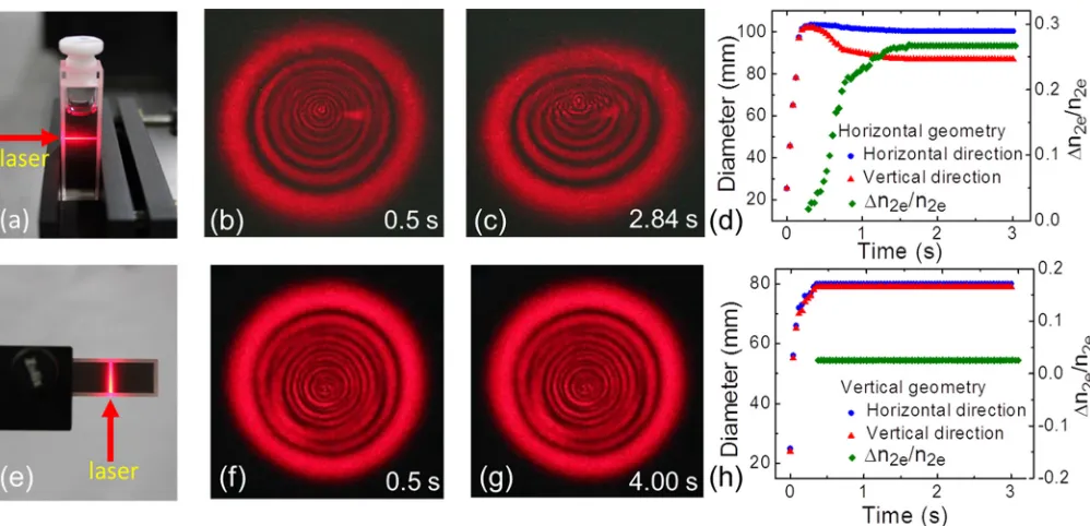
The graphene dispersions in N-methyl-2-pyrrolidone (NMP) were prepared using liquid phase exfoliation tech-nique.18 Different from the chemical exfoliation method,19 the liquid exfoliation does not use any high-residual chemi-cals or ions, which could result in a change of the physical and chemical properties of the exfoliated graphene nano-sheets,18 and thus can largely guarantee high quality of the graphene used in the experiments. Owing to the nonlinear SSPM effect, a series of concentric rings can be observed af-ter a focused cw He-Ne (633 nm) laser beam transmitting the graphene dispersions. The third-order susceptibility of gra-phene monolayer can be determined directly from the dif-fraction rings patterns.9In this experiment, it was found that the diffraction rings pattern was distorted rapidly after the incident laser beam horizontally passing through the gra-phene dispersions (see Figs. 1(a)–1(c)). As shown in Fig.
1(b), the initial diffraction pattern is nearly perfect concen-tric circles right after the horizontal incidence of the laser beam. In the subsequent few seconds, the upper half of the diffraction rings was collapsed to the center of the patterns, while the lower half retained the same (see Fig.1(c)). Figure
1(d), in which diameters of the SSPM patterns along the two
a)Authors to whom correspondence should be addressed. Electronic
addresses: [email protected] and [email protected]
orthogonal directions are depicted as functions of time, shows a dramatic reduction of the diameter in the vertical direction after it increases to a maximum in 0.32 s. In con-trast, the diameter in the horizontal direction decreases slightly after the maximum. On the other hand, the laser beam was designed to be incident at the graphene dispersions along the vertical direction, as shown in Fig.1(e). Under this geometry, the SSPM patterns retain unchanged with time, i.e., the collapse and deformation do not appear any more (see Figs. 1(f) and 1(g)). Figure 1(h) shows the diameters along the two orthogonal directions follow the same trend.
The SSPM is induced by the change of the intensity-dependent effective refractive index of graphene dispersions, which is expressed asne¼n0eþIn2e,9,12where n0e andn2e
are the effective linear and nonlinear refractive index, respec-tively, andIis the incident laser intensity. Thus, the distortion of the SSPM patterns should result from the change ofn0e
and/orn2e. Hereinafter, we demonstrate that the change ofn2e
dominates the distortion, rather than that ofn0e.
The change of n0eof the graphene dispersions is mainly
from two possibilities: The possible solvent bubbles induced by laser heating and the concentration variation of graphene caused by thermal convection. The following pressure experi-ment confirms that the change ofn0e resulting from solvent
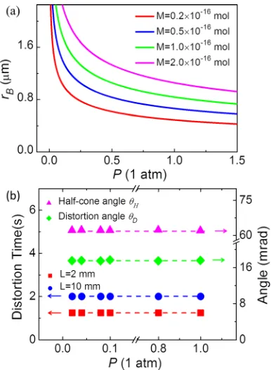
bubbles can be neglected. In the experiment, a cuvette with the graphene dispersions was placed in a vacuum chamber, the pressure of which can be controlled by a mechanical pump.20 The relationship between the bubble sizerB and the air
pres-surePcan be estimated approximately by the equation6
2c¼3MRT
4pr2 B
PrB; (1)
wherecis the surface tension,M is the number of moles of gas, R is the universal gas constant, and T is the absolute
temperature in the bubbles. From Eq. (1), bubble size as a function of atmospheric pressure can be deduced. As illus-trated in Fig.2(a), the bubble can increase dramatically when the pressure decreases nearly to zero. For instance, when the vacuum pressure changes from 1.00 atm to 0.02 atm, the cal-culated bubble sizerBcan increase from 0.835lm to 2.95lm
(M was assumed to be 1:01016 mol). The volume of the bubbles becomes 44 times greater, implying that a large vari-ation ofn0eof the graphene dispersions occurs and the
distor-tion pattern should change dramatically ifn0e dominates the
process. However, from Fig.2(b), it can be seen that the dis-tortion time, disdis-tortion angle, and half-cone angle keep stable when the air pressure decreases from 1.00 atm to 0.02 atm in the experiment. The results indicate that the change of n0e
resulting from solvent bubbles is negligible within our inci-dent laser power range (0–54 W/cm2).
The change of effective linear refractive indexDn0e of
the graphene dispersions caused by thermal convection is also very tiny. Suppose the graphene nanosheets can be com-pletely depleted during thermal convection, Dn0e should be
the maximum. It is noticed that the thickness of graphene nanosheets is much smaller than the irradiation wavelength and the observed scattering induced by the lateral size is also negligible. Therefore, Bruggeman effective medium theory is applicable to calculate the effective refractive indexn0eof
the graphene dispersions,21–23 by considering the refractive index and volume fraction of each composition
gNMP
n2NMPn 2 0e
n2
NMPþ2n20e
þgG
n2Gn 2 0e
n2 Gþ2n
2 0e
¼0; (2)
where nNMP¼1:47 andnG¼2:60 are the linear refractive
indices of NMP and graphene, respectively.24,25gGandgNMP
are the volume fractions of graphene and NMP in the disper-sion, respectively (gGþgNMP¼1). Here, we consider only
FIG. 1. (a) The horizontally incident geometry of the SSPM experiment. (b) An initial SSPM diffraction ring pattern and (c) the distorted pattern. (d) Diameters of the outermost ring along the horizontal and vertical directions and Dn2e=n2e as functions of time. (e)–(h) The vertically incident case.
(Multimedia view) [URL:http://dx.doi.org/10.1063/1.4871092.1] [URL:http://dx.doi.org/10.1063/1.4871092.2]
[image:3.612.57.556.492.733.2]the change of n0e of the graphene dispersions within the
quasi-cylinder volume of the incident laser beam. The hyper-bolic shape of the focused laser beam has less of an influence on the result. Therefore,gGcan be estimated by
gG¼
Nef fSdth
SL ¼
Nef fdth
L ; (3)
where Nef f48 is the effective number of graphene
mono-layer, which can be estimated by TNef f
monolayer ¼Ttotal, where
Ttotal is the transmittance of the graphene dispersions
(32.72% at 633 nm), andTmonolayer97.7% is the
transmit-tance of graphene monolayer.9,26Sis the cross sectional area of laser beam, dth ¼0:335 nm is the thickness of graphene
monolayer,27 andL¼10 mm is the thickness of quartz cuv-ette. According to Eqs.(2)and(3), then0eis calculated to be
(0:98106)nNMP, meaning that the order of magnitude of
the change of n0e caused by thermal convection of the
gra-phene nanosheets in NMP while irradiated by a cw He-Ne laser should be smaller than 106nNMP. Thus, the contribution
ofn0eto the distortion of SSPM pattern can be ignored in this
work.
The carriers within graphene nanosheets response in phase in the light field while constructing the SSPM ring pat-terns according to the theory of Wuet al.9Although the top half of the diffraction pattern distorts to a smaller amplitude, the interference pattern can be seen in Fig. 1(c), implying that the coherent response induced by graphene still remains. As we discussed above, the smaller amplitude of the interfer-ence pattern is largely induced by the change of effective nonlinear refractive index n2e of the graphene dispersions,
resulting from the variation of local graphene nanosheets concentration caused by the non-axis-symmetrical thermal
convections.14,28Indeed, the diffraction ring diameter of the graphene dispersions was decreased when the concentration of graphene nanosheets was reduced, as shown in Fig.3(a).
In the following part, we show theoretically that the half-cone angle of the diffraction pattern is only proportional ton2e and is independent onn0e. As a result, the change of
n2ecan be estimated by studying the distortion dynamics. As
illustrated in the inset of Fig.3(c), we definehDas the
distor-tion angle to measure the degree of distordistor-tion for the SSPM patterns and definehHas the half-cone angle. The half-cone
angle of the diffraction ring can be expressed as12
hH
k
2p
dDw
dr
max
; (4)
where DwðrÞ ¼ ð2p kÞ
ÐL
0n2eI rð ;zÞdzis the corresponding phase
shift of the laser beam after traversing the graphene disper-sions with the effective pathlength ofL.kis the wavelength of the laser, ris the transverse position in the beam. For a Gaussian beam, Eq.(4)can be rewritten in a compact form of
hHn2eC; (5)
where C¼ ½8IrL w2
0
expð2r2
w2 0
Þmax;r2 ½0;þ1Þ is a constant.
Equation(5)implies that the half-cone anglehHis only
pro-portional to the effective nonlinear refractive index n2e and
is independent onn0e. According to Eq.(5),Dn2e, the change
of n2ebefore and after the distortion, can be deduced in the
form of
Dn2e=n2e¼hD=hH; (6)
where hDandhH can be measured readily at different
inten-sities in the experiment. As shown in Fig.3(b),hDas well as
hHincreases quasi-linearly as the incident intensity increases,
implying a more severe distortion of the patterns at the higher intensities. Figure 3(c) gives the deduced Dn2e=n2e, which
increases from 14% to 28% when the incident intensity increases from 17.3 to 54.0 W/cm2.
From Eq. (6), we can directly see that the distortion originates from the change of n2e, which is ascribed to the
laser induced thermal convections,9,14rather than the change ofn0e. The convection induced by laser beam is analogous to
the onset of convection near a suddenly heated horizontal wire, which was investigated in details by Vest and Lawson.28Since graphene possesses high thermal conductiv-ity and optical absorption coefficient,5,26the dispersions can be effectively heated by the incident cw laser beam and the temperature gradient along the vertical direction arises, resulting in strong thermal convections near the focus in the dispersions, as illustrated in the inset of Fig.3(d). Density of graphene nanosheets in the upper part of the beam becomes less dense when strong convections occur, resulting in a reduction of the effective nonlinear refractive index.28 According to Ref.9, the total third-order nonlinear suscepti-bilityvð Þtotal3 N2ef fv
3 ð Þ
monolayer. When the local concentration of
graphene dispersions in the laser beam changes, Nef f and
hencevð Þtotal3 will be changed correspondingly. Asvð Þtotal3 is pro-portional to the effective nonlinear refractive index n2e,
n2e¼ ð1:2104p2=n20cÞv 3 ð Þ
total, n2e can then be tuned by FIG. 2. (a) Bubble size as a function of atmospheric pressureP. (b) The
[image:4.612.78.271.52.315.2]the change of graphene concentration caused by the thermal convection. Half of the laser beam is diffracted by the disper-sions with reducedn2e, leading to the upper part of the
dif-fraction rings distorting to the center of the patterns. On the contrary, the non-axis-symmetrical thermal convection is eliminated in the vertical incident geometry and the distor-tion phenomenon disappears, as shown in Fig.1(g). The vari-ation ofDn2e=n2ewith time is also calculated and depicted in
Figs.1(d)and1(h)for the two incident geometries.
In addition, we measured the distortion angle and half-cone angle of the SPM patterns at different temperatures. As shown in Fig. 3(d), when the temperature of the graphene dispersions increases from 20C to 100C, Dn2e=n2e is
20% at 20C and increases gradually to 37.5% at 100C.n2eof the graphene dispersions can be calculated via
the relation between the diffraction ring number and the inci-dent intensity,9and it is 1:13105 cm2/W in our experi-ment. Thus,Dnecan be tuned up to 0.05 (Dn2e=n2e¼0:375)
when Nef f is set to 700, larger than carrier induced one
(0.01) in InP, GaAs, InGaAsP29 and electric field induced one (0.01) in some organic materials, say, ATOP dyes.30
In summary, we show that the distortion of the diffrac-tion rings patterns in the horizontal incident geometry, while eliminated in the vertical one, is mainly attributed to the change of local graphene nanosheets concentration induced by the non-axis-symmetrical thermal convections. The rela-tive change of local nonlinear refracrela-tive indexDn2e=n2e can
be obtained directly by measuring the distortion angle and half-cone angle. Tuned by the incident intensity and disper-sion temperature, the relative change of the effective refrac-tive index of graphene dispersionsDn2e=n2ecan be spanned
from 0.14 to 0.375, implying potential applications in nonlinear optical modulation devices.
J.W. thanks the financial supports from the National 10000-Talent Program, CAS 100-Talent Program, NSFC (No. 61178007), STCSM Nano Project 11nm0502400, and
Shanghai Pujiang Program 12PJ1409400. S.F.Z. thanks the STCSM (No. 12ZR1451800) and NSFC (No. 61308034). N.N.D. thanks the China Postdoctoral Science Foundation (2012M520049) and NSFC (No. 61308087). L.Z. thanks the fi-nancial supports from NSFC (No. 51072207) and STCSM (No. 10XD1404600). W.J.B. gratefully acknowledges the China National High-end Foreign Experts Program (No. GDJ20130491010) and Science Foundation Ireland (SFI, 12/IA/1306).
1C. Lee, X. D. Wei, J. W. Kysar, and J. Hone,Science
321, 385 (2008).
2
A. A. Balandin, S. Ghosh, W. Z. Bao, I. Calizo, D. Teweldebrhan, F. Miao, and C. N. Lau,Nano Lett.8, 902 (2008).
3K. S. Kim, Y. Zhao, H. Jang, S. Y. Lee, J. M. Kim, K. S. Kim, J. H. Ahn,
P. Kim, J. Y. Choi, and B. H. Hong,Nature457, 706 (2009).
4
F. Bonaccorso, Z. Sun, T. Hasan, and A. C. Ferrari,Nat. Photonics4, 611 (2010).
5A. K. Geim and K. S. Novoselov,Nature Mater.6, 183 (2007).
6J. Wang, Y. Hernandez, M. Lotya, J. N. Coleman, and W. J. Blau,Adv. Mater.21, 2430 (2009).
7
E. Hendry, P. J. Hale, J. Moger, A. K. Savchenko, and S. A. Mikhailov,
Phys. Rev. Lett.105, 097401 (2010).
8H. Zhang, S. Virally, Q. L. Bao, L. K. Ping, S. Massar, N. Godbout, and P.
Kockaert,Opt. Lett.37, 1856 (2012).
9
R. Wu, Y. L. Zhang, S. C. Yan, F. Bian, W. L. Wang, X. D. Bai, X. H. Lu, J. M. Zhao, and E. G. Wang,Nano Lett.11, 5159 (2011).
10M. Horowitz, R. Daisy, O. Werner, and B. Fischer,Opt. Lett.
17, 475 (1992).
11
F. Bloisi, L. Vicari, F. Simoni, G. Cipparrone, and C. Umeton,J. Opt. Soc. Am. B5, 2462 (1988).
12S. D. Durbin, S. M. Arakelian, and Y. R. Shen,Opt. Lett.6, 411 (1981),
available athttp://www.opticsinfobase.org/ol/abstract.cfm?uri=ol-6-9-411.
13
W. Ji, W. Chen, S. Lim, J. Lin, and Z. Guo,Opt. Express14, 8958 (2006).
14
R. Karimzadeh,J. Opt.14, 095701 (2012).
15N. Konforti, E. Marom, and S.-T. Wu,Opt. Lett.13, 251 (1988). 16Y. Xu, Z. Liu, X. Zhang, Y. Wang, J. Tian, Y. Huang, Y. Ma, X. Zhang,
and Y. Chen,Adv. Mater.21, 1275 (2009).
17
Y. Zhou, Q. Bao, L. A. L. Tang, Y. Zhong, and K. P. Loh,Chem. Mater.
21, 2950 (2009).
18Y. Hernandez, V. Nicolosi, M. Lotya, F. M. Blighe, Z. Y. Sun, S. De, I. T.
McGovern, B. Holland, M. Byrne, Y. K. Gun’koet al.,Nat. Nanotechnol.
3, 563 (2008).
19C. Valles, C. Drummond, H. Saadaoui, C. A. Furtado, M. He, O. Roubeau,
L. Ortolani, M. Monthioux, and A. Penicaud, J. Am. Chem. Soc. 130, 15802 (2008).
FIG. 3. (a) Diameter of outermost dif-fraction ring as a function of effective number of graphene monolayers. Inset: Photographs of the corresponding SPM patterns. (b) Distortion anglehD,
half-cone angle hH, and (c) Dn2e=n2e as
functions of incident intensity. Inset: Illustration of the distortion angle and half-cone angle. (d) Dn2e=n2e versus
temperature of the graphene disper-sions. Inset: Illustration of the thermal convections in the graphene disper-sions by laser heating.
[image:5.612.52.407.52.308.2]20X. Cheng, N. Dong, B. Li, X. Zhang, S. Zhang, J. Jiao, W. J. Blau, L.
Zhang, and J. Wang,Opt. Express21, 16486 (2013).
21
G. A. Niklasson, C. G. Granqvist, and O. Hunderi,Appl. Opt.20, 26 (1981).
22W. T. Doyle,Phys. Rev. B39, 9852 (1989).
23F. J. Garcia-Vidal, J. M. Pitarke, and J. B. Pendry,Phys. Rev. Lett. 78, 4289 (1997).
24
S. Chen, W. Fang, J. Yao, and H. Zong,J. Chem. Eng. Data46, 596 (2001).
25Z. Ni, H. Wang, J. Kasim, H. Fan, T. Yu, Y. Wu, Y. Feng, and Z. Shen, Nano Lett.7, 2758 (2007).
26R. R. Nair, P. Blake, A. N. Grigorenko, K. S. Novoselov, T. J. Booth, T.
Stauber, N. M. R. Peres, and A. K. Geim,Science320, 1308 (2008).
27
Y. Huang, J. Wu, and K. C. Hwang,Phys. Rev. B74, 245413 (2006).
28C. M. Vest and M. L. Lawson,Int. J. Heat Mass Transfer15, 1281 (1972). 29B. R. Bennett, R. A. Soref, and J. A. Delalamo, IEEE J. Quantum
Electron.26, 113 (1990).
30