© 2017, IRJET | Impact Factor value: 5.181 | ISO 9001:2008 Certified Journal
| Page 1515
Adaptable D-STATCOM Performance as a Flexible Distributed
Generation in Mitigating Faults
Ganji Vivekananda
1*,
Dr K. Chandra Sekhar
21
Research scholar in Department of EEE, Acharya Nagarjuna University, Guntur, AP, India
2
Professor & Head, Department EEE , RVR & JC College of Engineering, Guntur AP, India
---***---Abstract -
This paper proposes an adaptableD-STATCOM(Distribution Static Compensator) and its new controller system, that have the capacity to both relieve a wide range of issues and work as a Distributed Generation (DG), when it supplies energy to sensitive loads while the principle utility source is separated (i.e. it is under islanded working condition). In this manner D-STATCOM works same as an adaptable DG (FDG) and subsequently, it is called Flexible DSTATCOM (FD-STATCOM).This paper approves the performance of FD-STATCOM framework to moderate power quality problems and enhance dissemination framework execution under all types of framework related aggravations and framework unbalanced faults, for example, Line-to-Line (LL) and Double Line to Ground (DLG) blames and supplies energy to delicate burdens under islanding condition. In this paper, the 12-beat D-STATCOM configuration with IGBT is outlined and the realistic based models of the D-STATCOM are created utilizing the PSCAD/EMTDC electromagnetic transient recreation program. The dependability and vigor of the control plots in the framework reaction to the voltage unsettling influences brought about by LL and DLG flaws and islanded working condition are obviously proved in the reenactment comes about.
Key Words: D-STATCOM Voltage Sags, Distribution
System, Faults, Energy Storage Systems, Islanding Condition
1.
INTRODUCTION
DG gives numerous potential advantages, for example, crest shaving, fuel exchanging, enhanced power quality and dependability, expanded proficiency, and enhanced natural execution. There ispopularity forutility DG) establishments because of their focal points of delay or redesigning the dispersion framework. Most DG units are associated with the conveyance framework through a shunt nonlinear connection such as a VSI or a Current Source Inverter (CSI) [1].
There are many sorts of DG. Among them are wind, biogas, fuel cells and sunlight based cells. By and large, these sources are connected to lattice through inverters and their principle capacity is to convey dynamic power into the
network. The DGs are intended to supply dynamic power or both dynamic and responsive power .Flexible DG frameworks would without a doubt be conceivable to execute incorporated capacities like consonant relief, unbalance mitigation, zero arrangement part concealment schemes, and so forth. The new patterns in power hardware converters make the execution of such different capacities plausible. A DG is islanded when it supplies energy to a few burdens while the principle utility source is detached. Islanding discovery of DGs is considered as a standout amongst the most essential angles while interconnecting DGs to the circulation framework. With the expanding infiltration and dependence of the dissemination frameworks on DGs, the new interface control procedures are being proposed [2]. This paper proposes an adaptable D-STATCOM framework intended to work in two unique modes. At first, it can moderate voltage lists brought about by LL and DLG issues. Furthermore, it can moderate voltage hangs brought about by three-stage open-circuit blame by opening the three periods of an electrical switch and disconnecting the fundamental power source (islanding condition).
© 2017, IRJET | Impact Factor value: 5.181 | ISO 9001:2008 Certified Journal
| Page 1516
transformer associated in shunt with air conditioningframework, and related control circuits, as appeared in Fig. 1.The arrangements that are more complex utilize multi-beat or potentially multilevel setups. The VSC changes over the dc voltage over the capacity gadget into an arrangement of three-stage air conditioning yield voltages. These voltages are in stage and combined with the air conditioner arrangement of system through the reactance of the coupling transformer [7]. A control technique in view of RMS voltage estimation has been introduced in [8] and [9] where they have been exhibited a PWM-based control conspire that requires RMS voltage estimations and no receptive power estimations are required. Furthermore, in this given technique, Clark and Park changes are not required. However, they have been examined voltage list/swell moderation due to simply stack variety while no adjusted and unequal shortcomings have been explored. In this paper, another control strategy for alleviating the heap voltage lists brought on by a wide range of blame is proposed. In [10] and [11], a Lookup Table is utilized to distinguish the relative pick up of PI controller, which is constructing just in light of Trial and Error. While in this paper, the relative pick up of the PI controller is settled at a same esteem, for a wide range of faults, by tuning the transformer reactance in a reasonable sum. At that point the heartiness and unwavering quality of the proposed technique is more than the specified strategies. In this technique, the dc side topology of the D-STATCOM is adjusted for moderating voltage bends and the impacts of framework blames on the delicate burdens are researched and the control of voltage droops are broke down and recreated.
1.1 THE PROPOSED FD-STATCOM STRUCTURE
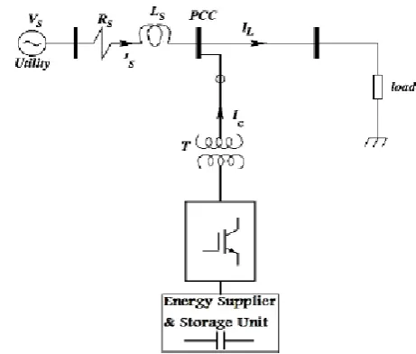
Not at all like the Unified Power Flow Controller (UPFC) which comprise from two sections, arrangement and shunt, to deal with the stream of dynamic power from one section to the other, FDG comprise of one section just, in light of the fact that it has a supply of the dynamic power from DG framework. Fig.1 demonstrates the schematic portrayal of the FDSTATCOM. The fundamental electronic square of the FD-STATCOM is the voltage source inverter that changes over an information dc voltage into a three-stage yield voltage at crucial frequency. These voltages are in stage and combined with the air conditioner framework through the reactance of the coupling transformer. Reasonable change of the stage and extent of the FD-STATCOM yield voltages permits viable control of dynamic and responsive power trades between the FD-STATCOM and the air conditioner framework.Fig. 2 demonstrates an average 12-beat inverter game plan using two transformers with their primaries
[image:2.595.334.565.215.411.2]associated in arrangement. The principal transformer is in Y-Y association and the second transformer is in Y-Y-Δ association. Every inverter works as a 6-beat inverter, with the Y-Δ inverter being postponed by 30 degrees regarding the Y-Y inverter. The IGBTs of the proposed 12-beat FD-STATCOM are associated against parallel with diodes for replacement purposes and charging of the DC capacitor [12]. This is to give a 30 degrees stage move between the beats and to decrease sounds produced from the FD-STATCOM. The FDSTATCOM is associated in shunt to the framework.
[image:2.595.307.556.441.535.2]Fig.1. Schematic representation of the FD-STATCOM
Fig.2.The 12-pulse FD-STATCOM arrangement
1.2 CONTROL STRATEGY
The piece chart of the control plot intended for the FD-STATCOM is appeared in Fig. 3. It is construct just in light of estimations of the voltage VRMS at the heap point.
The voltage blunder flag is gotten by contrasting the deliberate VRMS voltage and a
reference voltage, VRMS Ref. A PI controller forms the
© 2017, IRJET | Impact Factor value: 5.181 | ISO 9001:2008 Certified Journal
| Page 1517
the regulation file is Ma ≈ 1[13]. The balancing edgeδ is connected to the PWM generators in stage A. The points of stages B and C are moved 120 and 240 degrees, individually.
Fig.3. Control scheme designed for the FD-STATCOM
2.
PROPOSED CONTROL METHOD
In this paper, with a specific end goal to alleviate voltage lists brought about by LL and DLG blames and to supply energy to touchy load, once again strategy is proposed in which the FD-STATCOM and Super Capacitor Energy Storage framework (SCESS) are incorporated. Considering this reality that a wide range of blame may happen in appropriation framework, controller framework must have the capacity to relieve any sorts of voltage droops. The reconciliation and control of SCESS into a FD-STATCOM is produced to relieve such issues, upgrade control quality and enhance appropriation framework dependability [14]. The new strategy builds up the control ideas of charging and releasing the SCESS by DSTATCOM, and
approves the execution of a coordinated DSTATCOM/SCESS for enhancing circulation framework execution under a wide range of framework related unsettling influences furthermore, framework deficiencies, for example, LL and DLG issues and under islanded working condition. The SCESS is clarified as following:
Super capacitor is another vitality gadget developed as of late. It is otherwise called twofold layer capacitor. The electrical twofold layer capacitor is a novel vitality stockpiling part created in 1970s. Its post sheets are made of enacted carbon, which have colossal viable surface so the capacitance could achieve a few farad even thousands farad. When it is charged, the electric charges are suddenly disseminated negative and positive particle layers on the
interface between shaft sheets and electrolyte, so the super capacitor does not have electrochemical response and just have electric charges adsorption and desorption when it is charged and released. It has many merits, for example, high charge/release present, less upkeep, long life and some other immaculate execution. In the meantime, its little spillage current empowers it has long time of vitality stockpiling and the effectiveness could surpass 95% [15].
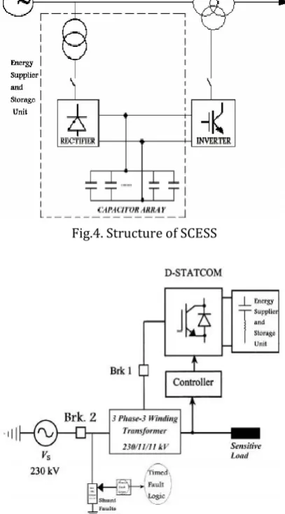
The structure of SCESS is appeared in Fig. 4. Its circuit is essentially made out of three sections: rectifier unit, vitality stockpiling unit, and inverter unit. Rectifier unit embraces three stage full extension rectifier to charge super capacitor and supply dc control vitality to inverter unit. Inverter unit receives three stage voltage inverter made out of IGBTs, it interfaces with power framework by means of transformer. When SCESS works ordinarily, voltage at dc side is changed over into air conditioning voltage with an indistinguishable recurrence from power lattice through IGBT inverter. At the point when just considering crucial frequency, SCESS can be equal to air conditioning synchronizing voltage source with controllable size and stage.
Vitality stockpiling unit i.e. super capacitor vitality stockpiling clusters are made out of numerous solid super capacitors. In the event that an extensive number of super capacitors are in parallel, in the meantime enhancing limit of force hardware gadgets in power transformation framework can be effortlessly made out of more vast limit SCESS, but operational unwavering quality and control adaptability won't be influenced. Super capacitor is effortlessly modularized, when required, and it is exceptionally advantageous in limit extension.
SCESS in light of DG associated with power matrix can be isolated into three capacity pieces: super capacitor clusters parts put away vitality, control vitality change framework in vitality change and transmission, and a coordinated control framework.
SCESS stores vitality as electric field vitality utilizing super capacitor exhibits. At the absence of vitality crisis or when vitality required, the put away vitality is discharged through control framework, quickly and precisely repaying framework dynamic and receptive power, to accomplish the adjust of force vitality and steadiness control.
Deciding the quantity of vitality stockpiling module can spare super capacitors, and further lessening volume, quality and cost of the vitality stockpiling unit.
It is expected that every super capacitor is spoken to as a comparable resistance req and proportionate perfect
© 2017, IRJET | Impact Factor value: 5.181 | ISO 9001:2008 Certified Journal
| Page 1518
bank are R=ns.req/np and C=np.ce/ns, individually; thatns and np are the quantity of solid super capacitors associated in arrangement and parallel for constituting stockpiling vitality module [16].
In this paper, SCESS is made of 10 clusters in parallel with ce =3(mF) and req=1(Ω) for each array, as
appeared in Fig. 4.
[image:4.595.75.285.317.504.2]Fig. 5 demonstrates a run of the mill circulation framework controlled by this strategy. Additionally, when Timed Fault Logic works LL and DLG flaws are applied, accordingly, the FD-STATCOM supplies receptive energy to the framework. In this strategy, the relative pick up is 300. The speed of reaction and heartiness of the control plan are obviously appeared in the reenactment comes about.
[image:4.595.76.280.329.696.2]Fig.4. Structure of SCESS
Fig.5.Distribution system with FD-STATCOM integrated with SCESS and controller
3. SIMULATION RESULTS
Fig. 5 demonstrates the test framework actualized in PSCAD/EMTDC to complete recreations for the FDSTATCOM. The test framework contains a 230 kV transmission framework. An adjusted load is associated with the 11kv, auxiliary side of the transformer. Brk.1 is utilized to control the operation time of the STATCOM. A 12-beat FD-STATCOM is associated with the tertiary twisting by shutting Brk.1 at 0.2s, for keeping up load RMS voltage at 1pu. A SCESS on the dc side give the FD-STATCOM vitality stockpiling capabilities. The reproductions are completed for both situations where the FDSTATCOM is associated with or detached from the framework.
The reproductions of the FD-STATCOM in blame condition are done utilizing LL and DLG deficiencies and under islanded working condition. In LL and DLG shortcomings the blamed stages are stages A and B while in islanded working condition, three conductors open by Brk.2 in 0.4 – 0.5 s. The term of the islanding condition are considered for around 0.1 s and the LL and DLG issues are considered for around 0.3 s. The shortcomings are applied at 0.4 s. The aggregate reenactment time is 1.6 s.
In this paper, the FD-STATCOM utilizes the proposed control technique to alleviate the heap voltage hangs because of a wide range of deficiencies. The reenactments are accomplished fora wide range of flaws presented in the 11 kV appropriation frameworks as takes after:
A.
Simulation results for line-to-line faultFigs. 6 and 7 demonstrate the RMS voltage and Vab (line voltage) at the heap point, separately,
for the situation when the framework works without FD-STATCOM and under LL blame. For this situation, the voltage drops by just about 20% regarding the reference esteem.
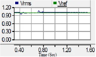
In t = 0.2 s, the FD-STATCOM is associated with the dispersion framework. The voltage drop of the touchy load point is alleviated utilizing the proposed control strategy. Fig.8 demonstrates the moderated RMS voltage utilizing this new technique where an exceptionally successful voltage direction is given.
Fig. 9 demonstrates the remunerated Vab at
© 2017, IRJET | Impact Factor value: 5.181 | ISO 9001:2008 Certified Journal
| Page 1519
lopsided LL blame by working Timed FaultRationale). Fig. 10 demonstrates the Vab recurrence
ranges amid alleviation of voltage hang that is introduced in percent. The THD in percent for Vab in
amid moderation of LL blame event is 0.034%. As a result of a 12-beat FD-STATCOM is utilized as a part of this paper, then the THD for Vab is little.
[image:5.595.61.287.125.456.2]Fig.6.The RMS voltage (VRMS) at PCC without FD-STATCOM
[image:5.595.342.547.276.553.2]Fig. 7.Vab at PCC without FD-STATCOM
Fig.10. Frequency spectrum for Vab during mitigation of LL fault
B.
Simulation results for Double Line to Groundfault
Figs. 11 and 12 demonstrate the RMS voltage and line voltage Vab at the heap point, separately, for the
situation when the framework works without FD-STATCOM and lopsided DLG blame is happened. The
RMS voltage faces with 20% decrease with regard to the reference voltage.
Figs. 13 and 14 demonstrate the repaid RMS voltage and moderated voltage of Vab at the heap point,
individually, under DLG blame utilizing proposed strategy. It is watched that the proposed technique has effectively relieved voltage list.
Fig.15 demonstrates the Vab recurrence ranges amid
alleviation of voltage hang. The THD of Vab in amid relief
of DLG blame event is exceptionally appropriate and 0.036%.
[image:5.595.39.268.510.635.2]Fig.11.The RMS voltage (VRMS) at PCC without FD-STATCOM
Fig.12.Vab Line voltage at PCC without FD-STATCOM
[image:5.595.348.544.587.703.2]© 2017, IRJET | Impact Factor value: 5.181 | ISO 9001:2008 Certified Journal
| Page 1520
Fig.14. Mitigated line voltage Vab at the load pointFig.15. Frequency spectrum for Vab during mitigation of DLG fault
C.
Simulation results under islanded operatingcondition
Figs. 16, 17 and 18 demonstrate the RM voltage, line voltages and load streams (versus kA) at the PCC, individually, for the situation when the framework works without FD-STATCOM and under islanded working condition.
Fig.16. VRMS at PCC without FD-STATCOM under islanding condition
Fig.17. Line voltages at PCC without FD-STATCOM
Fig.18. Load currents without FD-STATCOM in islanding condition
Figs. 19, 20 and 21 demonstrate the moderated RMS voltage, line voltages at the heap point and repaid stack currents, respectively, utilizing the proposed technique.
It is watched that the RMS stack voltage is near the reference esteem, i.e.1pu and FD-STATCOM can supply energy to touchy burdens, effectively.
Fig.22 demonstrates the Vab recurrence ranges amid moderation of voltage droop created by islanding condition.
Fig.19. Compensated RMS voltage
© 2017, IRJET | Impact Factor value: 5.181 | ISO 9001:2008 Certified Journal
| Page 1521
Fig.21.The mitigated load currents (in kA)Fig.22. Frequency spectrum for Vab under islanded
operating condition
Figs.19, 20 and 21 demonstrate the moderated RMS voltage, line voltages at the heap point and repaid stack currents, respectively, utilizing the proposed technique.
It is watched that the RMS stack voltage is near the reference esteem, i.e.1pu and FD-STATCOM can supply energy to touchy burdens, effectively.
Fig.22 demonstrates the Vab recurrence ranges amid moderation of voltage droop created by islanding condition.
3.
CONCLUSIONS
In this paper, an adaptable D-STATCOM is suggested that could both moderate lopsided issues, (for example, LL and DLG blames) and work as a DG, when it supplies energy to delicate burdens while the fundamental utility source is disconnected. As an outcome, D-STATCOM works same as a FDG and thusly, it is called FD-STATCOM. What's more, this paper has proposed another control strategy for alleviating the voltage droops, brought on by unequal deficiencies and islanding condition, at the PCC. The proposed strategy depends on incorporating FD-STATCOM and SCESS. This proposed control plan was tried under an extensive variety of working conditions (under unequal deficiencies and islanded working condition), and it was watched that the proposed strategy is exceptionally strong for each situation. Moreover, the directed VRMS voltage demonstrated a sensibly smooth profile. It was watched that the heap voltage is near the reference esteem, i.e., 1pu and the voltage droops are totally limited. In addition, the recreation results were
demonstrated that the charge/release of the capacitor is quick through this new technique (because of utilizing SCESS) and thus the reaction of the FD-STATCOM is quick
REFERENCES
[1]
E.Babaei, A.Nazarloo, and S. H. Hosseini, “Application of flexible control methods for D-STATCOM in mitigating voltage sags and swells,” in Proc. IEEE International Power and Energy Conference (IPEC), Singapore, 2010, pp. 590-595.[2] S.H.Hosseini, A.Nazarloo, and E.Babaei, “Application of DSTATCOM to improve distribution system performance with balanced and unbalanced fault conditions,” in Proc. IEEE Electrical Power and Energy Conference (EPEC), Canada, 2010.
[3] N. Mariun, H. Masdi, S. M. Bashi, A. Mohamed, and S. Yusuf, “Design of a prototype D-STATCOM using DSP controller for voltage sag mitigation,” in Proc. IEEE
International Power and Energy Conference,2004.
[4] E.Acha, V.G. Agelidis, O. Anaya-Lara, and T.J.E. Miller, “Power electronic control in electrical systems,” Newness Power Engineering Series, 2002, pp. 330-336.
[5] Z. Xi, B. Parkhideh and S. Bhattacharya, “Improving distribution system performance with integrated STATCOM and super-capacitor energy storage system,” in Proc. IEEE Power Electronics Specialists Conference, 2008, pp. 1390-1395.
[6] J. Zhang, “Research on super capacitor energy storage system for power network,” in Proc. IEEE International
Conference on Power Electronics and Drives Systems, 2005,
pp. 1366-1369.
[7] M. I. Marei, E. F. El-Saadany, and M. M. A. Salama, “A novel control algorithm for the DG interface to mitigate power quality problems,”IEEE Trans. Power Del., vol. 19, no. 3, pp. 1384-1392, July 2004.
[8] H. H.Zeineldin, E. F. El-Saadany, and M. M. A. Salama, “Impact of DG interface control on islanding detection and nondetection zones,” IEEE Trans. Power Del., vol. 21, no. 3, pp. 1515-1523, July 2006.
© 2017, IRJET | Impact Factor value: 5.181 | ISO 9001:2008 Certified Journal
| Page 1522
[10] M. I.Marei, E. F. El-Saadany, and M. M. A. Salama,“Flexible distributed generation: (FDG),” in Proc. IEEE Power Engineering Soc. Summer Meeting, 2002, vol. 1, pp. 49-53.
[11] G. F. Reed, M. Takeda, and I.Iyoda, “Improved power quality solutions using advanced solid-state switching and static compensation technologies,” in Proc. IEEE Power Engineering Society Winter Meeting, 1999, vol.2, pp. 1132-1137.
[12] S.Aizam, B. C. Kok, N.Mariun, H. Hizam, and N. I. Abd Wahab,“Linear feedback controller for D-STATCOM in DPG fault application,” in Proc. IEEE Universities Power Engineering Conference, 2006, vol. 3, pp. 986-990.
Ganji Vivekananda is a research scholar in department of Electrical and Electronics Engineering in Acharya Nagarjuna University, Guntur, Andhra Pradesh. India. He obtained his M.Tech degree JNTU College of Engineering, JNTU Hyderabad, Telangana, India. He completed Graduation in Electrical and Electronics Engineering, JNTU, Hyderabad, Telangana, India. His research area includes FACTS Controllers, Power Quality, Power System and Power Electronics. Dr.K.Chandra Sekhar presently working as a Professor & Head Electrical&Electronics Engineering Department R.V.R. & J.C. College of Engineering Guntur, Andhra Pradesh India. He obtained his Ph.D. in the Faculty of Electrical Engineering, J.N.T.U, Hyderabad in the Year 2008.He completed his M.Tech in Electrical Machines & Industrial Drives from Regional Engineering College (REC), Warangal in the Year 1994.He completed his graduation in Electrical&Electronics Engineering from Velagapudi Ramakrishna Siddhartha Engineering College, Vijayawada (Nagarjuna University) in the year 1991. His research area includes FACTS Controllers, Power Quality, Power System and Power Electronics.