© 2017, IRJET | Impact Factor value: 5.181 | ISO 9001:2008 Certified Journal
| Page 1850
GRID CONNECTED PHOTOVOLTAIC SYSTEM WITH ENERGY
MANAGEMENT SCHEME
Arun Thankachan, Aswathy J Das, Midhun Solomon
B Tech, Electrical and Electronics Engineering, MA College of Engineering,Kothamangalam
---***---Abstract -
A photovoltaic system connected to the utilitygrid with an energy management scheme is presented in this project work. The energy management scheme is incorporated with the grid connected PV system to maintain the power balance in the system. Grid connected PV system consists of solar panel, inverter and boost converter. The solar energy harvested from the PV panel is utilized to power local loads. In case of excess energy generation from the PV panel, the excess energy can be transferred to grid in order to supply the loads at grid side. If the energy generated from the PV system is not sufficient to meet the local load demand, additional power is taken from the grid. This system allows the bidirectional flow of power between the grid and PV system. The energy management module helps to monitor the energy usage and controls the inverter operation. The energy management module manages the energy demand of
the loads.
Key Words: Grid, Photovoltaic, Inverter, Boost coverter etc
1.INTRODUCTION
Numerous hassles related to conventional approaches for electrical energy generation have stimulated widespread deployment of renewable energy based technologies such as grid-connected photovoltaic (PV) systems. Governmental laws and policies of many countries are promoting this type of distributed generation in recent years. One of the examples for promoted distributed generation is the expansion of residential roof mounted grid connected single phase PV systems up to 5 kW. Majority of the grid connected PV systems employ maximum power point tracking (MPPT) to extract maximum electrical power from the panels. For a particular solar insolation level and ambient temperature, PV panels will have an operating point in its nonlinear voltage-current characteristics at which it can deliver maximum power output. MPPT enable the boost converter connected to PV module to track this optimal point in real time.
The intermittent nature of solar energy results the power output of PV systems to vary in a wide range. This characteristics of PV system many not be acceptable in many practical applications. Numerous methodologies have been proposed in literature for overcoming this limitation of PV systems. Many of these methodologies are limited to
simulation studies or theoretical analysis. This project presents a hardware proto-type of grid connected PV systems with energy management system, which can deliver stable power output irrespective of variation in solar energy. The prototype consists of PV panels, boost converter, single phase inverter and loads. A single phase inverter is power converter which converts the DC supply from the photo-voltaic system to AC supply. The controller is implemented using the PIC16F877 Microcontroller launch pad kit.
2. BLOCK DIAGRAM OF GRID CONNECTED
PHOTOVOLTAIC SYSTEM
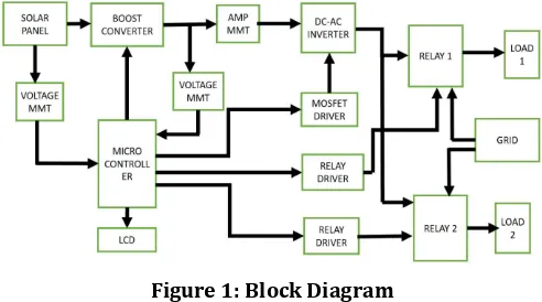
[image:1.595.310.556.573.710.2]A photovoltaic system connected to the utility grid with an energy management scheme. The energy management scheme is incorporated with the grid connected PV system to maintain the power balance in the system. Grid connected PV system consists of solar panels, one or several inverter and boost converters. The solar energy harvested from the PV panel is utilized to power local loads. In case of excess energy generation from the PV panel, the excess energy can be transferred to grid in order to supply the loads at grid side. If the energy generated from the PV system is not sufficient to meet the local load demand, additional power is taken from the grid. This system allows the bidirectional flow of power between the grid and PV system. The energy management module helps to monitor the energy usage and controls the inverter operation. The energy management module manages the energy demand of the loads.[1]
Figure 1: Block Diagram
© 2017, IRJET | Impact Factor value: 5.181 | ISO 9001:2008 Certified Journal
| Page 1851
The constant dc is then given as input to the DC-AC inverter.The inverter consists of 4 mosfet assembly. From among the 4 mosfet switches two sets of mosfets are initially ON and other two OFF. Then alternately first two are made OFF and the other two ON. This continues and the dc input from the boost converter is converted to ac output. The PIC microcontroller controls the switching action of the inverter and boost converter. A mosfet driver is used for the same. Also the power from the solar is measured by a voltage and current measurement method. The inverter is connected to two relays and both the relays are also connected to grid. Here we connect two loads and these two loads are connected to the two relays respectively. When conditions are right the loads are powered by the solar or the grid power.
We have three conditions based on which the loads are powered from the solar or the grid. The first one is when both the loads are supplied from the PV module. For high irradiation level when the solar output power is sufficient enough to supply both the loads, that is when the total load power is equal to or less than the solar power the two relays are made ON using relay driver and both the loads are supplied from the PV Module.
When the solar output power is not sufficient enough to supply both the loads, but only one load that is when the total load power is greater than the solar power but it can only supply a single load then only one relays is made ON using relay driver and the local load are supplied from the PV Module and the other load from the grid.
The third condition is when the solar power is very less and not at all sufficient to supply both the loads, then both loads are supplied from the grid. This energy management is controlled by the microcontroller and a proper backup supply is obtained.
3. CIRCUIT DIAGRAM AND COMPONENTS
USED
3.1 POWER SUPPLY
[image:2.595.323.536.105.270.2]The circuit diagram of the power supply are as shown in figure 2. The AC voltage, typically 220V rms, is connected to a transformer, which steps that AC voltage down to the level of the desired DC output. A diode rectifier then provides a full-wave rectified voltage that is initially filtered by a simple capacitor filter to produce a DC voltage. This resulting DC voltage usually has some ripple or AC voltage variation. A regulator circuit removes the ripples and also remains the same DC value even if the input DC voltage varies, or the load connected to the output DC voltage changes. This voltage regulation is usually obtained using one of the popular voltage regulator IC units.
Figure 2: Power Supply
3.2 MICROCONTROLLER
The microcontroller that has been used for this project is from PIC series. PIC microcontroller is the first RISC based microcontroller fabricated in CMOS (complimentary metal oxide semiconductor) that uses separate buses for instruction and data, allowing simultaneous access of program and data memory. The main advantage of CMOS and RISC combination is low power consumption resulting in a very small chip size with a small pin count. The main advantage of CMOS is that it has immunity to noise than other fabrication techniques. Various microcontrollers over different kinds of memories. EEPROM, EPROM etc are some of the memories of which FLASH is the most recently developed.
Technology that is used in pic16F877 is ash technology, so that data is retained even when the power is switched o. Easy Programming and Erasing are other features of PIC 16F877. The PIC start plus development system from microchip technology provides the product development engineer with a highly flexible low cost microcontroller design tool set for all microchip PIC micro devices. The pic start plus development system includes PIC start plus development programmer. The PIC start plus programmer gives the product developer ability to program user software in to any of the supported microcontrollers.
© 2017, IRJET | Impact Factor value: 5.181 | ISO 9001:2008 Certified Journal
| Page 1852
postscaler. There are two Capture, Compare, PWM modules.Capture is bit, max resolution is 12.5 ns. Compare is 16-bit, max resolution is 200 ns. PWM max. resolution is 10-bit It has 10-bit multi-channel Analog-to-Digital converter, Universal Synchronous Asynchronous Receiver Transmitter (USART/SCI) with 9- bit address detection and Brown-out detection circuitry for Brown-out Reset (BOR).
3.3 CURRENT MEASUREMENT
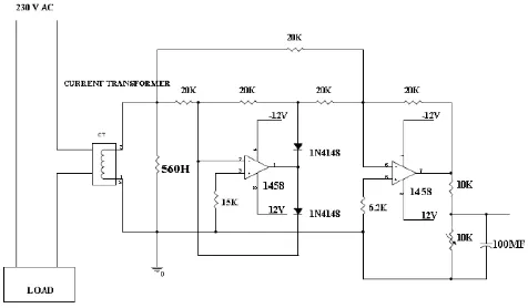
[image:3.595.311.557.158.305.2]This circuit as shown in figure 4.3 is designed to monitor the supply current. The supply current that has to monitor is stepped down by the current transformer. The step down current is converted by the voltage with the help of shunt resistor. Then the converted voltage is rectified by the precision rectifier. The precision rectifier is a configuration obtained with an operational amplifier in order to have a circuit behaving like an ideal diode or rectifier. The full wave rectifier is the combination of half wave precision rectifier and summing amplifier. When the input voltage is negative, there is a negative voltage on the diode, too, so it works like an open circuit, there is no current in the load and the output voltage is zero.
Figure 3: Current Measurement Circuit
When the input is positive, it is amplified by the operational amplifier and it turns the diode on. There is current in the load and, because of the feedback, the output voltage is equal to the input[6]. In this case, when the input is greater than zero, D2 is ON and D1 is OFF, so the output is zero. When the input is less than zero, D2 is OFF and D1 is ON, and the output is like the input with an amplification of R2 / R1. The full-wave rectifier depends on the fact that both the half-wave rectifier and the summing amplifier are precision circuits. It operates by producing an inverted half-wave-rectified signal and then adding that signal at double amplitude to the original signal in the summing amplifier. The result is a reversal of the selected polarity of the input signal. Then the output of the rectified voltage is adjusted to 0-5 V with the help of variable resistor VR1. Then ripples are filtered by the C1 capacitor. After the filtration the
corresponding DC voltage is given to ADC or other related circuit.
[image:3.595.41.279.389.528.2]3.4 VOLTAGE MEASUREMENT
Figure 4: Voltage Measurement
This circuit as shown in figure 4.4 is designed to monitor the supply voltage. The supply voltage that has to monitor is step down by the potential transformer. Usually we are using the potential transformer. The step down voltage is rectified by the precision rectifier. The precision rectifier is a configuration obtained with an operational amplifier in order to have a circuit behaving like an ideal diode or rectifier. The full wave rectifier is the combination of half wave precision rectifier and summing amplifier.
© 2017, IRJET | Impact Factor value: 5.181 | ISO 9001:2008 Certified Journal
| Page 1853
3.5 RELAY
Figure 5: Relay
A relay as shown in figure 5 is an electrically operated switch. Current owing through the coil of the relay creates a magnetic field which attracts a lever and changes the switch contacts. The coil current can be on or off so relays have two switch positions and they are double throw (changeover) switches. Relays allow one circuit to switch a second circuit which can be completely separate from the first. For example a low voltage battery circuit can use a relay to switch a 230V AC mains circuit. There is no electrical connection inside the relay between the two circuits; the link is magnetic and mechanical. The coil of a relay passes a relatively large current, typically 30mA for a 12V relay, but it can be as much as 100mA for relays designed to operate from lower voltages. Most ICs (chips) cannot provide this current and a transistor is usually used to amplify the small IC current to the larger value required for the relay coil. The maximum output current for the popular 555 timer IC is 200mA so these devices can supply relay coils directly without amplification[5].
Relays are usually SPDT or DPDT but they can have many more sets of switch contacts, for example relays with 4 sets of changeover contacts are readily available. Most relays are designed for PCB mounting but you can solder wires directly to the pins providing you take care to avoid melting the plastic case of the relay. The animated picture shows a working relay with its coil and switch contacts. You can see a lever on the left being attracted by magnetism when the coil is switched on. This lever moves the switch contacts. There is one set of contacts (SPDT) in the foreground and another behind them, making the relay DPDT.
3.6 Photovoltaic Cell
The density of power radiated from the sun at the outer atmosphere is 1.373 kW/m2.
Figure 6: Equivalent Circuit
The stand-alone photovoltaic energy system requires storage to meet the energy demand during period of low solar irradiation and night time. Battery storage in a solar system should be properly controlled to avoid catastrophic operating condition like over charging or frequent deep discharging. Storage batteries account for the most PV system failures and contribute significantly to both initial and the eventual replacement cost. Charge controllers regulate the charge transfer and prevent the battery from being excessively charged and discharged. Switch mode DC to DC converters are used to match the output of a PV generator to a variable load. DC to DC converters allow the charge current to be reduced continuously in such a way that the resulting battery voltage is maintained at a specified value[2].
3.7 BOOST CONVERTER
The output of a PV array is very low compared to bus voltage specifications. To meet the required bus voltage levels a boost converter with the desired step up gain should be properly designed and incorporated in between the PV array and the load. A Boost converter or step-up switch mode power supply that can also be called a switch mode regulator. It steps up the input voltage to produce a higher output voltage. The popularity of a switch mode regulator is due to its high efficiency, compact size and low cost. Generally, any basic switch power supply consists of the same basic power components: two switches, usually a
MOSFET, and a diode D, an inductor and an
output
[image:4.595.312.559.661.743.2]capacitor, all components are same as the buck and
buck-boost converter but placed in different circuit
locations.
© 2017, IRJET | Impact Factor value: 5.181 | ISO 9001:2008 Certified Journal
| Page 1854
Here, L is the inductor and R is the resistor which is consideras a load. Is is the current flow through the circuit. Switch is triggered by the pulse which is generated by PWM technique. Switch remains on during Ton cycle and off during Toff cycle so triggering depends on the duty cycle. Vdc is the D.C. input voltage supply which is taken from the bridge rectifier which converts A.C. input voltage into D.C output voltage.Vout is the output of the boost converter
which is larger than the input Vin.
4.SIMULATION MODELS AND RESULTS
[image:5.595.309.557.102.239.2]The detailed MATLAB model of Grid connected PV system is shown in figure 8. The different blocks used for this project are explained separately. The output of a PV is of low value and is always fluctuating. The output of PV is integrated to a boost converter so that fairly high and steady voltage is obtained.
Figure 8: Simulation Diagram
This voltage is given as input to the inverter. The high ac output thus obtained is fed to the loads. The loads are also connected to the grid. The load power supply is taken either from the grid or the PV module based on the conditions provided. When the solar output power obtained is sufficient enough to supply both the loads, then breaker 1 and breaker 3 is closed and both loads are supplied from the PV panel. When the solar output power is sufficient to supply only one load then breaker 2 and breaker 3 are closed and load 1 is supplied from the PV panel and the other from the grid. When the solar output power is insufficient to supply both the loads then breaker 1 and breaker 2 are closed and thus load 1 and load 2 are supplied from the grid.
4.1 PV MODULE
[image:5.595.37.287.326.439.2]The MATLAB model of the PV Module is shown in figure 9. Here the value of temperature and irradiation can be changed in the simulation for obtaining different solar outputs.
Figure 9: PV Module
4.2 MPPT TRACKING
To improve the efficiency of the solar panel MPPT is used. According to maximum power point theorem, output power of any circuit can be maximized by adjusting source impedance equal to the load impedance, so the MPPT algorithm is equivalent to the problem of impedance matching. Converter is used as impedance matching device between input and output by changing the duty cycle of the converter circuit. A major advantage of boost converter is that high or low voltage obtained from the available voltage according to the application. Output voltage of the converter depend on the duty cycle, so MPPT is used to calculate the duty cycle for obtain the maximum output voltage because if output voltage increases than power also increases. Perturb and Observe and constant duty cycle techniques are used, because this require less hardware complexity and low-cost implementations[4][7].
4.3 OUTPUT WAVEFORMS
4.3.1 For Irradiation= 700W=m2andTemperature = 303K
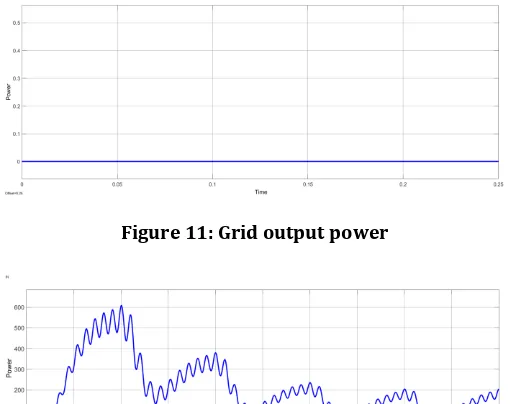
When the irradiation level is high and for a given temperature the PV output is sufficient enough to supply both the loads and the output power of inverter is equal to the total load power. So the grid output is zero.
[image:5.595.309.560.618.714.2]© 2017, IRJET | Impact Factor value: 5.181 | ISO 9001:2008 Certified Journal
| Page 1855
Figure 11: Grid output powerFigure 12: Inverter output power
Figure 13: Load 1 output power
Figure 14:Output voltage and current of load 2
Figure 15: Load 2 output power
4.3.2 For Irradiation= 250W=m2andTemperature = 303K
When the irradiation level is less and for a given temperature, the PV output is sufficient enough to supply only one load the output power of inverter is equal to power of load 1. And the grid output power is equal to the power of load 2.
Figure 16:Output voltage and current of load 1
Figure 17: Load 1 output power
Figure 18: Inverter output power
[image:6.595.34.289.98.300.2]© 2017, IRJET | Impact Factor value: 5.181 | ISO 9001:2008 Certified Journal
| Page 1856
Figure 20:Output voltage and current of load 2Figure 21: Load power2
4.3.3 For Irradiation= 150W=m2andTemperature = 303K
[image:7.595.245.556.39.632.2]When the solar output power is insufficient then both loads are powered from grid and the grid output power is equal to total load power. The inverter output power is zero.
Figure 22: Inverter output power
Figure 23: Grid output power
Figure 24:Output voltage and current of load 1
Figure 25: Load 1 output power
Figure 26:Output voltage and current of load 2
Figure 27: Load 2 output power
5. HARDWARE RESULTS
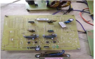
[image:7.595.37.289.436.536.2]© 2017, IRJET | Impact Factor value: 5.181 | ISO 9001:2008 Certified Journal
| Page 1857
Figure 28: Hardware SetupThe solar energy is harvested using the solar panel. The voltage is then boosted using boost converter. The output of the boost converter is constant DC. It is then given as input to the DC-AC inverter. The inverter consists of 4 mosfet assembly. From among the 4 mosfet switches two sets of mosfets are initially ON and other two OFF. Then alternately first two are made OFF and the other two ON. This continues and the DC input from the boost converter is converted to AC
output. The PIC microcontroller controls the switching
[image:8.595.39.271.98.260.2]action of the inverter and boost converter. A mosfet driver is used for the same. Also the power from the solar is measured by a voltage and current measurement method. The inverter is connected to two relays and both the relays are also connected to grid.Here we connect two loads and these two loads are connected to the two relays respectively. When conditions are right the loads are powered by the solar or the grid power. We have three conditions based on which the loads are powered from the solar or the grid. The first one is when both the loads are supplied from the PV module. For high irradiation level when the solar output power is sufficient enough to supply both the loads, that is when the total load power is equal to or less than the maximum solar power that can be generated which is 4W, the two relays are made ON using relay driver and both the loads are supplied from the PV Module. When the solar output power is sufficient enough to supply only one load, that is when the total load power is greater than the solar power which is 4W, then only one relays is made ON using relay driver and the local load which is load 1 is supplied from the PV Module and the other load from the grid. Here boost converter consists of 12mH inductor, two 10K resistors, diode, mosfet and 10mF capacitor. The driver circuit is also provided alongwith. The input to the boost circuit is variable dc and output is boosted constant DC. The voltage is constant and is set at 50V. This constant DC is given to the inverter.
Figure 29: Boost Converter Section
The inverter section as shown in figure 6.3 consists of the driver circuit and four mosfets. These are two sets of complementary mosfet. The are switched alternately. The gate pulses for switching are provided from the PIC board. Thus the output is AC voltage and this is provided to the relay. The relay is normally OFF, In that condition it is connected to the grid which is the supply voltage step down using autotransformer. When the solar supply is to be provided the relay is turned ON and then it is connected to the inverter and not the grid. Thus the loads are supplied.
Figure 30: Inverter Section
[image:8.595.341.525.418.533.2] [image:8.595.333.523.526.717.2]© 2017, IRJET | Impact Factor value: 5.181 | ISO 9001:2008 Certified Journal
| Page 1858
CONCLUSIONS
Conventional sources of power will not be able to address the energy crisis of tomorrow. Moreover the environmental price paid for conventional energy sources cannot be justified by a civilised society. In this context non-conventional source of power is the only solution among which solar power is the most promising one.
The photovoltaic system connected to the utility grid with an energy management scheme presented here, aims to maintain the power balance of connected networks.
The solar energy harvested from the PV panel is utilized to power local loads like household loads or street lights. In case of excess energy generation from the PV panel, the excess energy can be transferred to grid in order to supply the loads at grid side. If the energy generated from the PV system is not sufficient to meet the local load demand, additional power is taken from the grid. The energy management module helps to monitor the energy usage and controls the inverter operation. The energy management module manages the energy demand of the loads.
The simulation of the system is done using MATLAB and the results show that if the solar power generated is sufficient to meet the local load and grid side load, then no power is taken from the grid. If the solar power generated is just sufficient to meet the local load only, then the local load is supplied from PV panel and the other load from the grid. Whenever there is no power generation from the PV system, both loads are powered from the grid. In the present scenario where energy management and conservation are the needs of the hour, the presented grid connected photovoltaic system with energy management scheme can be implemented as an effective solution.
REFERENCES
[1] G Deepak, Jaya Bharath Reddy, et al, ` Hardware Implementation of Grid Connected PV System With Energy Management Scheme, ", IEEE International Conference on Electric Utility Deregulation and Restructuring Power Technologies, , 2013.
[2] Concettina Buccella, Carlo Cecati, Hamed Latafat, Kaveh Razi \A Grid Connected PV System with LLC Resonant DC-DC Converter ", Department of Industrial and Information Engineering and Economics , 2010;pp 1-5.
[3] Eduardo Romn, Ricardo Alonso, Pedro Ibaez, \Intelligent PV Module for Grid Connected PV Systems ", IEEE Transactions On Industrial Electronics.,,, vol. 53, no. 4, august 2006
[4] Mihai Albu, \Low-Cost Low-Power Microgrid with Photovoltaic Panels ,", 2014 International Conference and Exposition on Electrical and Power Engineering (EPE 2014), ,vol.2, 16-18 October, Iasi, Romania.
[5] P. Sritakaew and A.Sangswan, \On the Reliability Improvement of Distribution Systems Using PV Grid-Connected Systems", IEEE Trans. Power Del.,vol 24, no. 4, pp. 22762283, 2009.
[6] J. Robinson, D. Jovcic, and G. Jos, \Analysis and design of solar plant using a MV DC grid,", IEEE Trans. Power Del.,vol. 25, no. 4, pp. 21642173, 2010.
[7] Syafrudin Masri and Pui-Weng Chan, \Development of a Microcontroller-Based Boost Converter for Photovoltaic System", European Journal of Scientific Research, ISSN 1450-216X Vol.4, No.1,pp 38-47.
[8] Diary R. Sulaiman, Hilmi F. Amin and Ismail K.,"Design of High Efficiency DC-DC Converter for Photovoltaic Solar Home applications", Journal of Energy