© 2018, IRJET | Impact Factor value: 6.171 | ISO 9001:2008 Certified Journal | Page 2750
Numerical Analysis of Pin Fin by Varying Shape and Materials
Arun Eldhose
1, Dr. Benny Paul
2, Jelvin Tom Sebastian
31,3Student, Dept. of Mechanical Engineering M A College of Engineering, Kerala, India 2Professor Dept. of Mechanical Engineering M A College of Engineering, Kerala, India
---***---Abstract -
Fins are the surfaces that extend from an object.It helps to increase the rate of heat transfer and thereby increase the life and efficiency of the devices. Heat transfer is take place by Conduction, Convection, and Radiation. Fins are mainly used in the field of automobiles, electronic devices, etc. Constant area Straight fin, Variable area Straight fin, and Pin fin are the various types of fins. Among these Pin fins are used in electronic devices, computer CPU heat sinks, semiconductor devices etc. The shape and the materials used have great effect on the thermal performance of the fin. Different shaped fins are used for different applications and Aluminum is the most common material that used for making the fin.
In this work, cylindrical pin fin geometry was created by using the ANSYS software and the geometry was validated using an experimental paper. Finally an attempt is made to find out the Fin efficiency, Heat transfer Rate, Temperature distribution and Heat transfer coefficient of Pin fin by varying its geometry and material used.
Key Words: Fin Efficiency, Heat Transfer Rate, Heat
Transfer coefficient, Pin Fin, Thermal conductivity
1. INTRODUCTION
In the study of heat transfer, fins are surfaces that extend from an object to increase the rate of heat transfer to or from the environment by increasing convection. The amount of conduction, convection, or radiation of an object determines the amount of heat it transfers. The extended surfaces called fins are commonly used in the fields of automobiles, electronic components, electrical motors etc. to increase heat transfer rate and thereby increasing the life and efficiency of the devices. The heat transfer is mainly take place by three mechanisms named Conduction, Convection, and Radiation. Conduction is the transfer of heat by microscopic collisions of particles and movement of electrons within a body. Convection is the heat transfer due to bulk movement of molecules within fluids such as gases and liquids. Heat transfer due to emission of electromagnetic waves is known as Radiation.
Mainly three types of fins are there. They are constant area straight fin, variable area straight fin and pin
The most common materials are Aluminium and Copper. Aluminium is silver white in colour. It is a nonmagnetic ductile metal. It is easily available and its ore is Bauxite. Aluminium having the thermal conductivity value of 232.56 W/m-K. It is mechanically soft. Good resistance to corrosion, excellent thermal conductivity, good electrical conductivity, low density is its good properties.
Copper has good properties like its thermal conductivity, corrosion resistance, etc. Thermal conductivity value of Copper is around 401W/m-K. Copper is more expensive than Aluminium. But it has good conductivity, and corrosion resistance.
Pradeep singh et al, [1] prove that high rate of heat transfer is occur in case of the rectangular shaped extended surfaces. Shivdas Kharche et al, [2] state that when a notch is provided on the surface of a rectangular shaped fin its heat transfer rate and efficiency will be increased. He also varies the material of fin and the copper show more heat transfer than aluminium. Sandhya et al, [3] state that as length increased for a triangular fin its heat transfer rate will be increased. Sampath et al, [4] compared the temperature distribution of a cylindrical element at various points with help of simulation software by providing thermal conductivity and heat transfer coefficient with the boundary conditions. And the result was almost same expect at the middle of the cylinder. Amol B. Dhumne and Hemant S, [5] show that to obtain high heat transfer rate the cylindrical pin with perforation can be used. The efficiency varies depending on clearance ratio and inter spacing ratio. M. P. Shah et al. [6] conducted the study on cylindrical pin fin by varying the materials as copper, AA1100, AA2011 and he concluded that efficiency will be increased with increase in thermal conductivity of materials. Pratapa Reddy et al [7] do an experiment on a pin fins made of different materials (aluminum, copper) and composite bars (brass and aluminum , copper and aluminum) and he found that the composite made of copper and aluminum shows higher efficiency than the solid pin fin. Dr. Bahdur [8] has evaluated the orthotropic pin fin made of polymers. And he proved that coefficient of thermal performance for polymer fins is higher compared to aluminum. U S Gawai et al, [9] conducted a test on pin fin made of brass and Aluminium metals in terms of its dimensionless numbers of like Nusselt number (Nu) and Reynolds number (Re) and the results was heat transfer co-efficient & efficiency of aluminum fin is greater than that of brass fin.
2. NUMERICAL MODEL
A cylindrical Pin Fin model was created by using the ANSYS software. The materials used are Aluminum, Copper, combination of Aluminium and Brass and a combination of Aluminium and Copper. The dimensions of model are given below. The figure 1 represent the cylindrical pin fin model created in ANSYS software
© 2018, IRJET | Impact Factor value: 6.171 | ISO 9001:2008 Certified Journal | Page 2751 Figure 1 : Cylindrical Pin Fin Model created In ANSYS
3. MODEL VALIDATION
[image:2.595.285.554.50.252.2]The model created was validated based on an experiment conducted by Y. Pratapa Reddy in the cylindrical Pin Fin. The model validation is done based on comparing current numerical results like fin efficiency, heat transfer rate, temperature distribution and heat transfer coefficient of the cylindrical pin fins with Aluminium, Copper, Aluminium and Brass and Aluminium and Copper
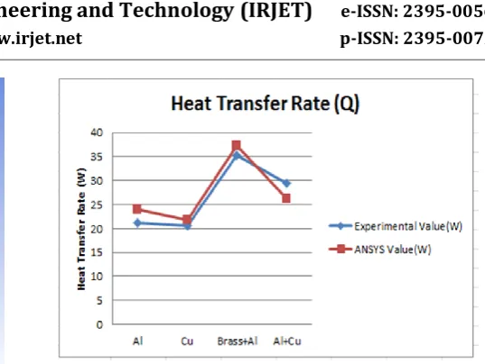
[image:2.595.313.554.362.527.2]Figure 2 represent the fin efficiency validation. Fin efficiency was validated and there was only a 2.4% of variation in case of cylindrical pin fin with Aluminium. For cylindrical Pin Fin with Copper the percentage of variation is 1.75, and for Aluminium and Brass it is 5.4%. The figure 3 show the validation graph of heat transfer rate. Similarly the heat transfer rate (Q) was also validated with the experimental and numerical value.
Figure 2 : Validation of Fin Efficiency of present model
Figure 3: Validation of Heat Transfer Rate of Present model
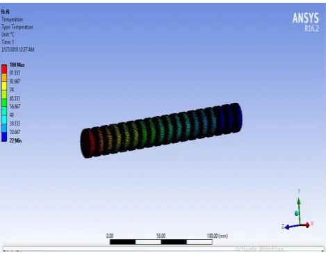
[image:2.595.44.280.509.678.2]Figure 4 represent the temperature distribution of a cylindrical pin fin with aluminium. The red line on the graph indicates the ANSYS value and the blue line represent the experimental value. There was only a small variation in the temperature distribution. So the model is valid.
Figure 4 : Validation of temperature distribution of Cylindrical pin fin with Aluminium
[image:2.595.315.554.569.731.2]© 2018, IRJET | Impact Factor value: 6.171 | ISO 9001:2008 Certified Journal | Page 2752 Figure 5 represent the temperature distribution of a
[image:3.595.44.283.155.312.2]cylindrical pin fin with Copper. The red line on the graph represents the ANSYS value and the blue line indicates the experimental value.
[image:3.595.309.557.276.449.2]Figure 6 : Validation of temperature distribution of Cylindrical pin fin with Brass and Aluminium
Figure 7: Validation of temperature distribution of Cylindrical pin fin with Aluminium and Copper
Figure 8: Validation of Heat Transfer Coefficient of Present Model
Figure 6 represent the temperature distribution of cylindrical pin fin with Brass and Aluminium. Figure 7 represent the temperature distribution of cylindrical pin fin with Aluminium and Copper. Figure 8 represents the validation of Heat Transfer Coefficient of a cylindrical pin fin. The blue line represents the experimental value and the red line indicates the ANSYS value. In case of cylindrical pin fin with Aluminum the percentage of variation is 7.9 and for copper it is about 8.3 %. Thus the created model was validated with the fin efficiency, temperature distribution, heat transfer rate and heat transfer coefficient.
4. ANALYSIS OF DIFFERENT SHAPED PIN FIN
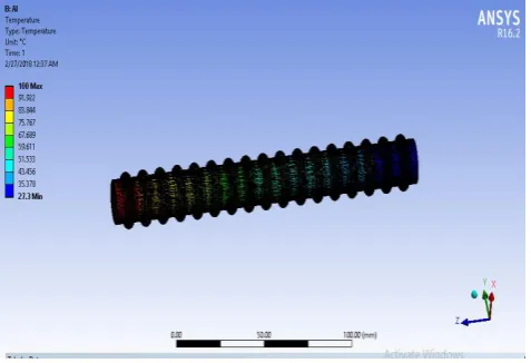
[image:3.595.51.275.368.522.2] [image:3.595.316.551.480.662.2]4.1 Cylindrical Pin Fin with Groove
Figure 9: Cylindrical Pin Fin Geometry with Grooves
Figure 10: Temperature Distribution of Cylindrical Pin Fin With Grooves
[image:3.595.41.284.569.733.2]© 2018, IRJET | Impact Factor value: 6.171 | ISO 9001:2008 Certified Journal | Page 2753
[image:4.595.271.551.50.255.2]4.2 Cylindrical Pin Fin with Rings
[image:4.595.42.282.111.272.2]Figure 11: Cylindrical Pin Fin Geometry with Rings
Figure 12: Temperature Distribution of Cylindrical Pin Fin With Rings
Figure 11 represent the cylindrical pin fin geometry with rings and figure 12 represent the corresponding temperature distribution.
[image:4.595.43.282.305.468.2]4.3 Cylindrical Pin Fin with Rectangular Fin
Figure 13: Cylindrical Pin Fin Geometry with Rectangular Fin
Figure 14: Temperature Distribution of Cylindrical Pin Fin with Rectangular Fin
[image:4.595.319.549.312.467.2]4.4 Cylindrical Pin Fin with Helix
Figure 15: Cylindrical Pin Fin Geometry with Helix
Figure 16: Temperature Distribution of Cylindrical Pin Fin with Helix
[image:4.595.318.549.497.651.2] [image:4.595.43.282.578.736.2]© 2018, IRJET | Impact Factor value: 6.171 | ISO 9001:2008 Certified Journal | Page 2754
[image:5.595.38.295.108.265.2]4.5 Efficiency Variation with Varying Shape
Figure 17: Variation of fin efficiency with varying the shape of Pin Fin
The above graph represents the variation of fin efficiency by varying the shape of the Pin Fin. The red line indicates the Pin Fin with Copper and blue line represents the Pin Fin with Aluminum. The maximum efficiency is obtained in the case of Cylindrical Pin Fin with rectangular pin fin. The increasing order of efficiency of pin fin with different shape is as below.
Pin fin with groove < Pin fin with ring < Pin fin with helix < Pin fin with rectangular fin.
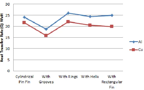
[image:5.595.314.571.412.537.2]4.6 Variation in Heat Transfer Rate
Figure 18: Variation in Heat Transfer Rate with varying the shape
The above graph represents the variation of Heat Transfer Rate with the variation in shape. In this graph also red line indicates the Pin Fin with Copper and blue line represents the Pin Fin with Aluminum. The maximum Heat Transfer Rate is obtained in the case of Cylindrical Pin Fin with Rings. The increasing order of Heat Transfer Rate of Pin Fin is given below.
Pin fin with grooves < Pin fin with helix < Pin fin with rectangular fin < Pin fin with rings
5. ANALYSIS OF DIFFERENT MATERIALS PIN FIN
The analysis was also carried out by varying the materials of the Pin Fin. Commonly used pin fin materials are Aluminum (Al) and Copper (Cu).Aluminum having the thermal conductivity value of 232.56 W/m-K and the Copper having the thermal conductivity of 401 W/m-K. As the material change the thermal conductivity value will be change hence the efficiency of fin will also be varied. Hear composite material was taken for the study. Composite material is a material made from two or more constituent materials with significantly different physical or chemical properties that, when combined, produce a material with characteristics different from the individual components. The individual components remain separate and distinct within the finished structure. Hear Carbon Fiber material is used as new material for pin fin. Carbon fiber is one of the interesting carbonaceous materials with excellent mechanical properties and ultimate chemical stability. Generally, materials containing more than 92 wt. % of carbon and forming a fiber shape are defined as carbon fibers. P-100S and P-120S are taken for the study. P-100S having the thermal conductivity value of 520 W/m-K and P-120S having the thermal conductivity value of 640 W/m-K.
[image:5.595.44.288.444.597.2]5.1 Efficiency Variation with Varying Materials
Figure 19: Variation of fin efficiency with varying the materials of Pin Fin
Figure 6.1 represent the graphical representation of variation in the efficiency of pin fin with varying the material of the fin. From the graph it is clear that highest efficiency is obtained in the case of P-120S carbon fiber used pin fin. Next higher efficiency is for P-100S Carbon Fiber. Beryllium Oxide is the other material that was taken for our study other than the carbon fiber material. And this BeO have the efficiency higher than the Aluminum but not higher than Copper. The increasing order of efficiency of Pin Fin with varying the materials is given below
© 2018, IRJET | Impact Factor value: 6.171 | ISO 9001:2008 Certified Journal | Page 2755
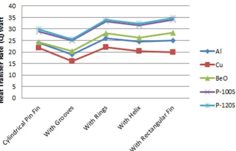
5.2 Variation in Heat Transfer Rate
Figure 21 represent the graphical representation of variation in Heat Transfer Rate by varying the materials of Pin Fin. Highest Heat Transfer Rate are for Pin Fin with P-120S Carbon Fiber material. As we compare the Heat Transfer Rate for Pin Fin with Beo and P-100S carbon fiber, higher Heat Transfer Rate is for Pin Fin with P-100S carbon fiber. The increasing order of Heat Transfer Rate of Pin Fin with varying the materials is given below.
[image:6.595.44.280.253.404.2]Pin Fin with Cu < Pin Fin with Al < Pin Fin with BeO < Pin Fin with P-100S < Pin Fin with P-120S
Fig-21: Variation in Heat Transfer Rate with varying the materials of Pin Fin
7. CONCLUSIONS
In this work Pin Fin geometry was created by using the ANSYS software. Fin efficiency, Heat transfer Rate, Temperature distribution and Heat transfer coefficient of Pin fin was found out. And the model created was validated based on an experiment conducted by Y. Pratapa Reddy in the cylindrical Pin Fin. Various analysis was carried out by using the software by varying the shape and materials of Pin Fin. From that it was clear that the efficiency of the Pin Fin will be varied by varying the shape and the material used. Five different shapes and five different materials are considered for the study. Maximum efficiency was obtained in the case of Cylindrical Pin Fin with rectangular Fin on it. As the shape of the Pin Fin varies the cross-sectional area of the fin will be varies that lead to change in the efficiency. Maximum efficiency was obtained in the case of pin fin with P-120S carbon fiber is used. Each material has different Thermal Conductivity. As the Thermal Conductivity varies the efficiency will also be change.
The maximum efficiency was obtained in the case of Cylindrical Pin Fin with Rectangular Fin on it made up of P-120S Carbon Fiber. And the value is 87.75%. The maximum Heat Transfer Rate was obtained in the case of Cylindrical Pin Fin with Rectangular Fin on it made up of P-120S Carbon Fiber. And the value is 34.79Watt.
REFERENCES
[1] Pardeep Singh, Harvinder lal, Baljit Singh Ubhi, “Design and Analysis for Heat Transfer through Fin with Extensions”, International Journalof Innovative Research in Science, Engineering and Technology, ISSN 2319-8753,Vol. 3, Issue 5, pp 12054- 12061,May 2014.
[2] Shivdas S. Kharche, Hemant S Farkade, “Heat Transfer Analysis through Fin Array by Using Natural Convection, ISSN 2250- 2459, Volume2, Issue 4, pp 595-598. April 2012.
[3] Sandhya Mirapalli, Kishore P S, “Heat Transfer Analysis on a Triangular Fin”, International Journal of Engineering Trends and Technology, ISSN: 2231-5381,Volume 19, Number 5, pp 279-284. Jan 2015. [4] Sampath S S, Anil Antony Sequeira, Chithirai Pon
Selvan M, Sawan Shetty, “Comparative Thermal Analysis of Bar Element Connected to Different Heating Sources”,International Journal of Emerging Technology and Advanced Engineering, ISSN:2250-2459,Volume 4, Issue 12, pp :72-78, December 2014. [5] Amol B Dhumne, Hemant S Farkade, “Heat Transfer Analysis of Cylindrical Perforated Fins in Staggered Arrangement”, International Journal of Innovative Technology and Exploring Engineering (IJITEE), ISSN: 2278-3075, Volume-2, Issue-5, April 2013.
[6] M P Shah, K S Mehra, S Gautam, P Negi, “Transient and Steady State Analysis of Fin Using FEM for Different Material”, International Journal for Research in Applied Science and Engineering Technology, Vol. 2, Issue VI, pp 36-40, June 2014.
[7] Y Pratapa Reddy, B Jithendra Kumar, G Raju, Dr.Ch Srinivasa Rao, “Fabrication and Thermal Analysis of Composite Pin-Fin”, International Journal of Core Engineering and Management, ISSN:2348-9510, Volume 2, Issue 5, pp 77-89, August 2015.
[8] Raj Bahadur, Thesis, “Charecterization, modelling, and Optimization of polymer Composite Pin Fins”,(2005).