© 2018, IRJET | Impact Factor value: 6.171 | ISO 9001:2008 Certified Journal | Page 205
Wind Analysis and Design of G+11 Storied Building Using STAAD-Pro
1
Vikrant Trivedi,
2Sumit Pahwa
---***---Abstract: This study presents a comparative study of wind
loads to decide the design loads of a G+11 building. The significance of this examination is to estimate the design loads for a structure which is subjected to wind loads in a particular region. It is well known fact that the wind loads may be estimated in particular zone with a specified zone factor. Then the wind load of that zone can also be estimated based on the basic wind speed and other factors of that particular region. However, the wind velocity is stochastic and time dependent. In the present study a multi-storied building is analyzed for wind loads using IS 875 code. In this Analysis, G+11 storied building is considered and applied various loads like wind load, static load and results are studied and compared between with wind load or without wind load.
Keywords: Zone factor, wind loads, design loads, high rise buildings.
I.
INTRODUCTIONThe importance of wind engineering is emerging in India ever since the need for taller and slender buildings is coming forth. Considering the ever increasing population as well as limited space, horizontal expansion is no more a viable solution especially in metropolitan cities. There is enough technology to build super-tall buildings today, but in India we are yet to catch up with the technology which is already established in other parts of the world. Nowadays, Construction of high rise building is a basic need because of scarcity of land. Conventional method of manual design of high rise building is time consuming as well as possibility of human errors. So it is necessary to use some computer based software which gives more accurate results and reduce the time. STAAD-PRO is the structural software is nowadays accepted by structural engineers which can solve typical problem like static analysis, wind analysis, using various load combination to confirm various codes.
Many times, wind engineering is being misunderstood as wind energy in India. On the other hand, wind engineering is unique part of engineering where the impact of wind on structures and its environment being studied. More specifically related to buildings, wind loads on claddings are required for the selection of the cladding systems and wind loads on the structural frames are required for the design of beams, columns, lateral bracing and foundations.
Wind in general governs the design when buildings are above 150 m height. However the other force which effect most on high rise building are the lateral forces caused by earthquakes. When buildings grow taller, they become flexible and they are moving away from the high frequency earthquake waves. This paper describes wind and seismic analysis of high-rise building in various zones of Indian subcontinent. For the analysis purpose a twelve story reinforced concrete framed structure is selected. The wind loads are estimated by Indian code IS: 875 (Part-3)-1987.
II.
RCC FRAME STRUCTURESAn RCC framed structure is basically an assembly of slabs, beams, columns and foundation inter -connected to each other as a unit. The load transfer, in such a structure takes place from the slabs to the beams, from the beams to the columns and then to the lower columns and finally to the foundation which in turn transfers it to the soil. The floor area of a R.C.C framed structure building is 10 to 12 percent more than that of a load bearing walled building. Monolithic construction is possible with R.C.C framed structures and they can resist vibrations, wind load, earthquake and shocks more effectively than load bearing walled buildings. Speed of construction for RCC framed structures is more rapid.
III.
WIND ANALYSISThe basic wind speed (Vb) for any site shall be obtained IS 875 and shall be modified to get the design wind velocity at any height (Vz) for a chosen structure.
Vz = Vb k1 k2 k3
Where, Vz = design wind speed at any heig ht z in m/s, Vb = Basic wind speed in m/s, k1 = probability factor (risk
Coefficient), k2 = terrain roughness and height factor and
k3 = topography factor
The basic wind speed map of India, as applicable at 10 m height above mean ground level for different zones of the country selected from the code. The design wind pressure at any height above mean ground level shall be obtained by the following relationship between wind pressure and wind velocity.
© 2018, IRJET | Impact Factor value: 6.171 | ISO 9001:2008 Certified Journal | Page 206
Where, Pz = wind pressure in N/m 2 at height z and Vz =
design wind speed in m/s at height z.
IV.
METHODOLOGY [image:2.612.340.553.75.279.2]A Model of G+11 storeyed is developed, analysis and design using STAAD-Pro software. Building plan size is 15 m × 15 m. The building is situated in Bhopal in zone 2. Following specifications are given to the structure:
Table 1: Building Specifications
Column 0.3 m x0.3 m Beam 0.3 m x0.3 m
Slabs 0.18 m
parapet wall 0.1 m Live load 2 Kn/m2 Floor finish 1kN/m2 Grade of concrete M 25
Grade of steel Fe 415 No. of storey G+11
Total height 36 m Height of ground storey 3 m
Height of floor to floor 3 m Spacing of frame along length 3 m Spacing of frame along width 3 m
These values are provided as a input to the STAAD-Pro software for drawing, analysis and designing purposes.
Supports: The base supports of the structure are assigned as fixed.
Figure 1: RCC building frame with dimensions
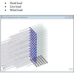
Loading: The loadings were calculated partially manually and rest was generated using STAAD-Pro load generator. The loading cases were categorized as:-
Dead load
Live load
[image:2.612.325.585.356.613.2] Wind load
Figure 2: Applying Wind Load on RCC Building frame
Self-weight: The self weight of the structure can be generated by STAAD-Pro itself with the self weight command in the load case column.
[image:2.612.61.267.508.691.2]© 2018, IRJET | Impact Factor value: 6.171 | ISO 9001:2008 Certified Journal | Page 207
[image:3.612.322.579.113.515.2]and the load on the floor per sq m. Calculation of the load per sq metre was done considering the weight of beam, weight of column, weight of RCC slab, weight of terracing, external walls, internal walls and parapet over roof.
Figure 3: G+11 RCC 3D building design
V.
RESULTS & DISCUSSIONSGraph shows the maximum deflection occurs when the wind load in x-direction acting on the structure. As height increases, deflection is also increases. Hence graph of height v/s deflection varies linearly.
Figure 4: Height vs. deflection of G+11 RCC building frame
[image:3.612.57.267.143.322.2]The maximum deflection (mm) for G+11 building has been shown in table-2, whereas in Figure-5, the nature of graph for G+11 building for both cases i.e. no wind and wind can be studied.
Table 2: Deflection with wind or without wind effect in x direction
G+11
Storey height(m) Max. Deflection(mm) No Wind Wind
36 7.9 15.231
33 7.82 14.933
30 7.624 14.462
27 7.32 13.795
24 6.908 12.935
21 6.386 11.882
18 5.759 10.64
15 5.031 9.212
12 4.203 7.604
9 3.28 5.824
6 2.269 3.885
3 1.173 1.814
Figure 5: Graph shows deflection with wind or no wind effect on RCC frame
Graph shows the maximum force occurs when the wind load in x-direction acting on the structure. Effect of the wind load in z-direction is approximately same. As height increases, magnitude of force is also increases. It gives the details for beam such Grade of concrete, steel, sectional dimensions, cover and section-wise top and bottom reinforcement details for flexural and shear requirement. Similarly for column, it provide interaction ratio as per Clause 39.6, IS 875: Part III. It also provides the data for concrete take off for beam, column and slab. Steel bar diameter and according the weight requirement is provided by STAAD Pro.
0 2 4 6 8 10
3 6 9 12 15 18 21 24 27 30 33 36
D
ef
le
ct
io
n
s
in
m
m
Building Height in metre
Height vs deflection
0 2 4 6 8 10 12 14 16
3 6 9 121518212427303336
De
fl
ec
tion
s
in
m
m
Building Height in metre
No Wind
[image:3.612.34.290.444.622.2]© 2018, IRJET | Impact Factor value: 6.171 | ISO 9001:2008 Certified Journal | Page 208
VI.
CONCLUSIONSTAAD PRO is versatile software has the capability to calculate the reinforcement needed for any concrete section, to find lateral deflection due to earthquake load.
The program contains a number of parameters which are designed as per IS: 875(Part 3).
Various structural action is consider on members such as axial, flexure, torsion etc according to their response.
The wind loads are estimated for a ten storied RC framed structure and eleven storied RC Framed Structure. Based on the results obtained the following conclusions are made:
The wind loads increases with height of structure.
Wind loads are more critical for tall structures than the earthquake loads.
Structures should be designed for loads obtained in both directions independently for critical forces of wind.
REFERENCES
1. A E. Hassaballa, Fathelrahman M. Adam., M. A. Ismaeil, "Seismic Analysis of a Reinforced Concrete Building by Response Spectrum Method", IOSR Journal of Engineering (IOSRJEN), Vol. 3, Issue 9 (September. 2013), PP 01-09.
2. Ashok kumar N, Navaneethan M, Naviya B, Gopalakrishnan D, "Planning, Analysis & Design of Hospital Building Using Staad Prov8i", International Journal of Scientific & Engineering Research, Volume 8, Issue 4, April-2017.
3. B. Gireesh Babu, "Seismic Analysis and Design of G+7 Residential Building Using STAADPRO", International Journal Of Advance Research, Ideas And Innovations In Technology, Volume3, Issue3, 2017.
4. Gaurav Kumar, Megha Kalra, "Review Paper On Seismic Analysis Of RCC Frame Structures With Floating Columns" , International journal of advanced technology in engineering and science, Vol. No.4, Special Issue No. 01, February 2016.
5. Gauri G. Kakpure, Ashok R. Mundhada, "Comparative Study of Static and Dynamic Seismic Analysis of Multistoried RCC Building by ETAB: A Review", International Journal of Emerging Research in Management &Technology, Volume-5, Issue-12, December 2016.
6. Gourav Sachdeva, Phrangkupar Thabah, Ericton Nonkyngynrih, "Analysis & behavior of RC Building Frame with Different Locations of Floating Columns", International Journal of Innovative Research in Science, Engineering and Technology, Vol. 5, Issue 6, June 2016.
7. Harman, Hemant sood, "Analyzing the Effect of Cross-Sectional Change of Column on Symmetrical R.C.C. Frame Structure" International Journal of Engineering Research & Technology (IJERT), Vol. 6 Issue 06, June - 2017.
8. K Venu Manikanta, Dr. Dumpa Venkateswarlu, "Comparative Study On Design Results Of A Multi-Storied Building Using STAAD Pro And ETABS For Regular And Irregular Plan Configuration", International Journal of Research Sciences and Advanced Engineering, Volume 2, Issue 15, PP: 204 - 215, September’ 2016.
9. Kavita K. Ghogare, "Seismic Analysis & Design of RCC Building", International Journal of Research in Advent Technology, Vol.3, No.2, February 2015.
10. Mahesh Ram Patel, R.C. Singh, “Analysis of a tall structure using STAAD pro providing different wind intensities as per 875 Part-III”, International Journal of Engineering Sciences & Research Technology, May, 2017.
11. Mohit Sharma, Dr. Savita Maru, "Dynamic Analysis of Multistoried Regular Building", IOSR Journal of Mechanical and Civil Engineering, Volume 11, Issue 1 Ver. II (Jan. 2014), PP 37-42.
12. Pachchigar Foram N., Patel Falguni R., Patel Minal H, "Development of Multi-Storeyed RCC Building Model with Soft Storey in STAAD PRO", Global Research and Development Journal for Engineering, March 2016.
© 2018, IRJET | Impact Factor value: 6.171 | ISO 9001:2008 Certified Journal | Page 209
14. Priyanka Soni, Purushottam Lal Tamrakar, Vikky Kumhar, "Structural Analysis of Multistory Building of Differentshear Walls Location and Heights", International Journal of Engineering Trends and Technology (IJETT), Volume 32, Number 1,February 2016.