© 2017, IRJET | Impact Factor value: 5.181 | ISO 9001:2008 Certified Journal
| Page 247
STRUCTURAL AND MODAL ANALYSIS OF CRANE HOOK WITH
DIFFERENT MATERIALS USING FEA
Rahul Tarale
1, Rahul Dalavi
2, Suraj Patil
3, Amol Patil
41,2,3,4
Student, Dept. of Mechanical Engineering, MMEC, Belagavi, Karnatak. India.
---***---Abstract -
Stress analysis plays an important role inthe design of structures like crane hook under loading conditions. Crane hook is a reliable lifting component being used in industries. Structure failure of crane hook occurs because of the stress induced due to repetitive loading and unloading conditions. In this study, solid modelling of crane hook having trapezoidal cross-section referring to one of its existing design is done using CATIA V5. Further, analyses are carried out in ANSYS Workbench. Further, fatigue analysis is performed on this model. Also, Modal analysis is carried out to determine the vibration characteristics such as natural frequencies and mode shapes. The combination of frequency and amplitude is found to be efficient method for reducing or controlling applied forces which generate stress.
Key Words:
Crane Hook, Static Analysis, Fatigue Analysis,Modal Analysis, Ansys 14.
1. INTRODUCTION
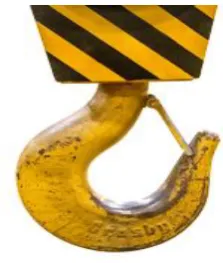
[image:1.595.371.483.198.330.2]Crane hooks are highly liable components and are always subjected to failure due to accumulation of large amount of stresses which can eventually lead to its failure. Crane hooks are the components which are generally used to elevate the heavy load in industries and constructional sites. A crane is a machine, equipped with a hoist, wire ropes or chains and sheaves used to lift and move heavy material. Cranes are mostly employed in transport, construction and manufacturing industry. Every year, incorrect lifting procedures cause injuries, loss of work time and property. People, machinery, loads, methods and the work environment, are all important factors for correct lifting. Provided that enough safety measures are fully implemented, lifting accidents can be reduced.
Fig 1.0 Crane Hook
1.1 Literature Survey
Following literatures are studied,
A.Gopichand and Lakshmi (2013)[1] have done optimization of design parameters for crane hook using TAGUCHI method. The analysis is done and the optimum combination of input parameters is determined for minimum von-mises stress. Rashmi Uddanwadiker (2013)[2] has made stress analysis of crane hook and the results are validated by using PHOTO ELASTICITY. Ajeet Bergaley and Anshuman Purohit (2013)[3] made a structural analysis of a crane hook using finite element method. The hook was tested in UTM machine in tension to locate the area having maximum stress and to locate the yield point. Ms. Mamta .R. Zade 2017[4] studied fatigue analysis on crane hook on different materials.
2. MATERIAL PROPERTIES
Materials selected for crane hook are Structural Steel and Aluminium Alloy the properties of materials are given below in Table 2.1
Structural Steel Alluminium Alloy Young's Modulus
MPa 2.e+005 0.71e+005
Poisson's Ratio 0.3 0.33
Tensile Yield
© 2017, IRJET | Impact Factor value: 5.181 | ISO 9001:2008 Certified Journal
| Page 248
Tensile Ultimate
Strength MPa 460 310
Density Kg/m3 7850 2270
Table 2.1 Material Properties
1.2 Standards for Assessment of Strength of
Crane hook
American Society of Mechanical Engineers (ASME) B30.10
This Standard presents a coordinated set of rules that may serve as a guide to government and other regulatory bodies and municipal authorities responsible for the guarding and inspection of the equipment falling within its scope.
a. Hook design shall meet generally accepted hook design standards and be compatible with the requirements of ASME B30.10.
b. Hook material shall have sufficient ductility to permanently deform before failure at the ambient temperatures at which the hook will be used.
c. Field-fabricated hooks shall meet the requirements of this section and shall be approved by a qualified engineer.
3. MODELING OF CRANE HOOK
[image:2.595.316.547.79.294.2]The crane hook is modeled using CATIA V5 R20 of trapezoidal cross section given dimensions, as shown in below fig.
Fig 3.1 2-D Spline Generation
Fig 3.2 3-D Solid Model
4.
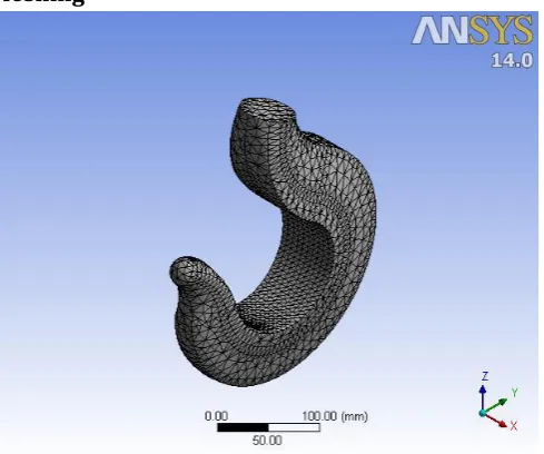
Finite Element Analysis
using Ansys
The finite element analysis (FEA) is a numerical technique for solving problems which are described by partial differential equations or can be formulated as functional minimization.
[image:2.595.313.558.405.609.2]Meshing
[image:2.595.59.267.534.712.2]© 2017, IRJET | Impact Factor value: 5.181 | ISO 9001:2008 Certified Journal
| Page 249
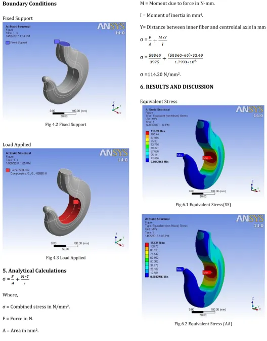
Boundary Conditions
Fixed Support
Fig 4.2 Fixed Support
Load Applied
Fig 4.3 Load Applied
5. Analytical Calculations
σ =
Where,
σ = Combined stress in N/mm2.
F = Force in N.
A = Area in mm2.
M = Moment due to force in N-mm.
I = Moment of inertia in mm4.
Y= Distance between inner fiber and centroidal axis in mm
σ =
σ =
σ =
114.20 N/mm2.6. RESULTS AND DISCUSSION
Equivalent Stress
[image:3.595.31.560.99.773.2]Fig 6.1 Equivalent Stress(SS)
© 2017, IRJET | Impact Factor value: 5.181 | ISO 9001:2008 Certified Journal
| Page 250
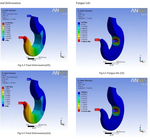
[image:4.595.42.568.95.583.2]Total Deformation
Fig 6.3 Total Deformation(SS)
Fig 6.4 Total Deformation(AA)
[image:4.595.46.285.120.309.2]Fatigue Life
Fig 6.5 Fatigue life (SS)
[image:4.595.309.561.122.333.2]© 2017, IRJET | Impact Factor value: 5.181 | ISO 9001:2008 Certified Journal
| Page 251
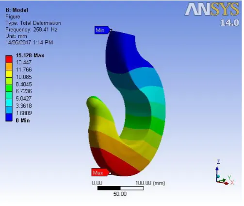
ModalFig 6.7 Mode I (SS)
Fig 6.8 Mode I (AA)
Stress Vs frequency response
Graph 6.1 Amplitude vs Frequency (SS)
Graph 6.2 Amplitude vs Frequency (AA)
Material Load in
N
Stress in Ansys
(Mpa)
Analytical Stress result
(Mpa)
% error
Structural
steel 58860 114.20 112.99 1.059
Alluminium
[image:5.595.318.559.131.282.2]© 2017, IRJET | Impact Factor value: 5.181 | ISO 9001:2008 Certified Journal
| Page 252
Table 6.1 Comparison of stressesMaterial Load
N
Deformation
mm
Structural steel 58860 0.4138
[image:6.595.307.558.202.546.2]Alluminium alloy 58860 1.1693
Table 6.2 Total Deformation
Fatigue analysis data
Material Min. Fatigue Life Max. Fatigue Life
Structural steel 2.1046E5 1E6
Alluminium alloy 3.7322E6 1E6
Table 6.3 Comparison of Fatigue Life
7. Conclusion
The results of stress analysis calculated from FEA for different materials such as Structural Steel and Aluminium Alloy. For the different Material, It is observed that keeping the 6 tone load with different Materials we will get different results, but from the above table it is found that the Alluminium Alloy gives minimum stress. Further Fatigue analysis is done on the materials from that it is found that Alluminium Alloy can withstand the maximum number of fatigue cycles before failure. Further modal analysis is done on materials and from that it is found that at first fundamental natural frequency, the total deformation of structural steel is less than the alluminium alloy. Hence, we can conclude that structural steel is more preferred during vibrations.
REFERENCES
[1].“Optimization of design parameters for crane hook using Taguchi method”, by Mr. A. Gopichand, Ms.R.V.S.Lakshmi,Mr.B.Maheshkrishna.International journal of innovative research in science, engineering and technology ,vol. 2, issue 12, december 2013
[2].Rashmi Uddanwadiker, “Stress Analysis of Crane Hook and Validation by Photo-Elasticity”, Engineering, 2011, 3, 935-941.
[3].Ajeet Bergaley, Anshuman Purohit “Structural Analysis of Crane Hook Using Finite Element Method”23196386, Volume-1, Issue-10, September 2013
[4].Ms. Mamta .R. Zade Volume: 04 Issue: 01 | Jan -2017 Irjst Finite Element Analysis And Fatigue Analysis Of Crane Hook With Different Materials.
BIOGRAPHIES
Mr. Rahul Tarale is pursuing his bachelor’s degree in mechanical engineering in MMEC Belagavi, India. His area of interests is FEA field.
Mr. Rahul Dalavi is pursuing his bachelor’s degree in mechanical engineering in MMEC Belagavi, India. His area of interests is FEA field.
Mr. Suraj Patil is pursuing his bachelor’s degree in mechanical engineering in MMEC Belagavi, India. His area of interests is Design Engineering field.