© 2017, IRJET | Impact Factor value: 5.181 | ISO 9001:2008 Certified Journal | Page 944
Study on Economics of Superstructure of Post-tensioned Highway
Bridge in Co-relation with Span to Depth Ratio
Ashish Chandra
1, L.P.Shrivastava
21
PG Student,
2Professor
1,2
Department Of Civil Engineering, M.M.College of Technology, NH-06, Raipur
Chhattisgarh Swami Vivekananda Technical University, Bhilai, Chhattisgarh, India
---***---Abstract - Span-to-depth (Slenderness ratio) ratio is an important bridge design parameter that affects structural behavior, construction costs and aesthetics. A study of 86 constant-depth girders indicates that conventional ratios have not changed significantly since 1958. These conventional ratios are now questionable, because recently developed high-strength concrete has enhanced mechanical properties that allow for slenderer sections.
Based on material consumption, cost, and aesthetics comparisons, the thesis determines optimal ratios of a 7-span highway viaduct constructed with high-strength concrete. Two bridge types are investigated: cast-in-situ on false work box-girder and cast in situ solid slabs. Results demonstrate that total construction cost is relatively insensitive to span-to-depth ratio over the following ranges of ratios: 10-35 and 30-45, for the two bridge types respectively. This finding leads to greater freedom for aesthetic expressions because, compared to conventional values (i.e. 18-23 and 22-39), higher ranges of ratios can now be selected without significant cost premiums.
Key Words: Highway Bridge, Slenderness ratio, span to depth ratio, Box girder, Solid slab
1. INTRODUCTION
The bridge design is very complicated design and in the designing of bridge deck the most important parameter is span to depth ratio which is also called as slenderness ratio. This ratio is generally used to fix the superstructure depth and it is chosen during the conceptual designing before any detailed calculation performed. The selection of the ratio at an early stage of the process of design gives the approximate dimension which is necessary for the analysis of bridge girders and cost efficiency and aesthetic merits of the design in comparison with alternative design concept. Span to the depth ratio is generally selected based on the field experience and some values used in previously constructed bridges with satisfactory performance. The ratio can also be determined by optimizing the combinations of ratios and superstructure depth to create cost efficient and aesthetic structure but this requires an iterative process therefore the optimization of the span to
depth ratio in every design concept, it is common to select ratios from the given ranges of conventional values.
[image:1.595.300.562.465.588.2]The selection of span to depth ratio is generally critical in the design of bridge with girders because the cost of materials and construction of the superstructure is directly affected by span to the depth ratio. For example, using high span to depth ratio reduces the volume of concrete and increases the requirement of prestressing force and simplifies the construction, because in a lighter structure the cost of the bridge is highly dependent on the proportion of the superstructure, so the selection of span to depth ratio is very important for economy. Some proven ranges of span to depth ratios over the past decades given by different organization and Authors for different types of bridges, like; cast in situ box girder, cast in situ slab, and precast segmental box girder shown below in table 1.1,
Table 1.1 Recommended Ratios for Box-Girder
Organization/Author Year Span to depth ratio Leonhardt 1979 12 to 16 ACI-ASCE 1988 25 to 33 Menn 1990 17 to 22 AASHTO 1994 25 Cohn &Lounis 1994 12 to 20 AASHTO-PCI-ASBI 1997 25
Recommended ratios for Cast in Situ Slab
Organization/Author Year depth ratio Span to Leonhardt 1979 18 to 36
ACI-ASCE 1988 24 to 40
Menn 1990 25
AASHTO 1994 37
Cohn &Lounis 1994 22 to 29
Hewson 2003 20
© 2017, IRJET | Impact Factor value: 5.181 | ISO 9001:2008 Certified Journal | Page 945 2. Literature Review
Miss. P.R. Bhivgade (2001)[1] in her paper has studied a simply supported Box Girder Bridge for two lane road made up of prestressed concrete which is analysis for moving loads as per Indian Road Congress (IRC:6) specification, Prestressed Code (IS: 1343) and also as per IRC: 18-2000 specifications. The analysis was done by using SAP 2000 14 Bridge Wizard and prestressed with parabolic tendons in which utilize full section. The various slenderness ratios considered to get the proportioning depth at which stresses criteria and deflection criteria get within the permissible limits recommended by IS codes. It is concluded that the basic principles for proportioning of concrete box girder help designer to design the section. For the torsion of superstructure box girder shows better resistance. The various slenderness ratios are carried out for Box Girder Bridges, deflection and stress criteria satisfied well within recommended limits. As the depth of the box girder increases, the prestressing force decreases and the number of cables decrease.
Rajamoori Arun Kumar, B. Vamsi Krishna (2014)[7] in their paper has studied the practical approach that on a major bridge having 299 meters span, 36 no’s of PSC Beams & 8 no’s of RCC Beams. The main code that follow in this course is IS: 1343. The title is Code of Practice for Pre-stressed Concrete published by the Bureau of Indian Standards. Remembering that IS: 456 - 2000 which is the Code of Practice for Structural Concrete. Some of the provisions of IS: 456 are also applicable for Pre-stressed Concrete.
The following conclusion were made –
1. Shear force and bending moment for PSC T-beam girder are lesser than RCC T beam Girder Bridge which allow designer to have less heavy section for PSC T-Beam Girder than RCC T-Girder for 24 m span.
2. Moment of resistance of steel for both PSC and RCC has been evaluated and conclusions drawn that PSC T-Beam Girder has more capacity for 24 m and more than 24m of span.
3. PROBLEM IDENTIFIC ATION
The study of 86 used bridges has been done to presents the variations of span-to-depth ratios. Specifically, the study determines the range of ratios typically used for construction and examines its variations over the past 49 years. Two types of bridge decks are to be analyzed. (i) box-girder bridge deck (ii) solid slab bridge deck
3.1 Some Existing bridges and their span to depth ratio in
3.1.1 Cast in situ Box-Girder Bridge
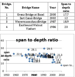
[image:2.595.308.562.303.565.2]First 44 cast-in-situ box-girders with constant depth throughout the length are investigated. Table 2-1 provides the basic information of each bridge. Additional information, including the span of the bridges, dimension of girders, detail of designer and references, is given in Appendix A.1. Graph 3-1 shows the variation of span-to-depth ratios with respect to the span lengths and compares these ratios with the recommended values described in chapter 1. Graph 3-2 shows the variation of span to depth ratio with respect to the completion years.
Table no. 2.1 Summary of Cast in Situ Box Girder. Bridge.
No. Bridge Name Year Span to depth ratio 1 Grenz Bridge at Basel 2000 17.7 2 Sart Canal-Bridge 2002 12 3 WeyermannshausBridge 1987 18.9 4 Eastbound Walnut Viaduct 1986 23
Graph 3-1 variation of span to depth ratio of box Graph 3-1 demonstrates that all 44 cast-in-situ box-girders have span lengths varies between 35.4m and 138 m and demonstrates span-to-depth ratios that ranges varies from 11.4 to 29.5. The graph shows that 42 out of 44 bridges (95%) investigated have span lengths varies from 35m to 75m which is the typical range for constant-depth cast in situ box-girders as suggested by Hewson . You can see in above the frequency plot on top of the graph are bridge numbers that relate each data point to its corresponding bridge in Table 3-1. The red line shows the border of large concentration of bridges that have span-to-depth ratios varies between 17.7 and 22.6. In fact, 34 out of 44 bridges (75%) have ratios within the range of values
17.7 12 18.9
23
11.4 22.2
18.2 18.2 18.2 20 21.6
17.7 18.5 18.5 18.5 28.1
12.9 12.8 16
20.8 20.8
29.5
20 20.9
14.7 20 20 20 20 20 20 20
15.1
21.3 18.1
22.5 19.3 22.6 21.2
0 10 20 30 40
1950 1960 1970 1980 1990 2000 2010
span to depth
ratio
Year
span to depth ratio
© 2017, IRJET | Impact Factor value: 5.181 | ISO 9001:2008 Certified Journal | Page 946 suggested by Menn (17 to 22) and Hewson (20) which are
based on existing bridges with acceptable performance. 3.1.2 Cast-in-Situ Solid Slab
[image:3.595.310.560.512.693.2]In addition to situ box-girders, 28 cast-in-situ constant-depth solid slab bridges are also investigated.
Table 3.1 Summary of cast in situ solid slab
Bridge
No. Location Year
Span to Depth
Ratio 1 Khandeshwar Bridge 2000 20.3 2 Spadina Ave. Bridge #16, Hwy 401 1967 22.2 3 Spadina Ave. Bridge #18A, Hwy 401 1967 22.2 4 Spadina Ave. Bridge #18B, Hwy 401 1967 22.2 4. Methodology & Analysis
4.1 Analysis Overview
The purpose of this analysis is to compute the amount of prestressing force and the concrete strength needed to satisfy design requirements for bridges with varying span lengths and slenderness ratios. These material consumption results are then used to compute the cost of construction as a function of span-to-depth ratio. By analyzing the variations in construction cost and aesthetic impacts, the study determines the most economical span to depth ratios for different bridge types like box girder bridge, solid slab bridge etc . The two types of post-tensioned bridge are considered ie cast-in-situ box-girder, cast-in-situ solid slab.
4.2 DESIGN AND ANALYSIS
4.2.1 Analysis of Box Girder Bridge Deck
Analysis is performed on 22 cases with span lengths (interior) of 35m, 50m, 60m, and 75 m and slenderness ratios of 10, 15, 20, 25, 30, and 35. This set of span lengths is chosen because cast-in-situ box-girders are economical for spans up to about 100 m according to Menn (1990) and bridges with longer spans need to be haunched in order to reduce self weight. The end spans are made 10 m shorter than interior spans to balance moments along the entire bridge and to make simpler the treatment of prestressing in the study.
.
Graph 4.1 Variation of concrete volume with span by depth ratio for different span
Graph 4.2 Variation of span to depth ratio for different span with depth
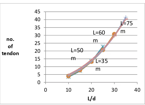
Graph 4.3 Variation of no. of strands with span by depth ratio
0.00 200.00 400.00 600.00 800.00 1000.00 1200.00 1400.00
5 15 25 35 45
concrete volume
in cubic meter
L/d
L=75m
L=60m
L=50m
L=35m
0 1 2 3 4 5 6 7 8
5 15 25 35 45
depth
L/d
L=75m
L=60m
L=50m
L=35m
0 5 10 15 20 25 30 35 40 45
0 10 20 30 40
no. of tendon
L/d
L=75
m
L=60
m
L=50
m
L=35
© 2017, IRJET | Impact Factor value: 5.181 | ISO 9001:2008 Certified Journal | Page 947 Graph 4.4 Variation of reinforcement with span by
depth ratio
Graph 4.5 Variation of concrete volume with span by depth ratio for different span
Graph4.6 Variation of span to depth ratio for different span with depth
Graph 4.7 Variation of no. of strands with span by depth ratio
Graph 4.8 Variation of no. reinforcement with span by depth ratio
5. COST ANALYSIS
This cost study investigates the changes in superstructure and total cost of construction, which are based on the previously described material consumption results, when slenderness ratio varies. Comparison of these costs reveals the optimal slenderness ratio for each type of bridge. The study also demonstrates the cost benefits of using the optimal ratios instead of conventional ratios.
0 2000 4000 6000 8000 10000 12000 14000 16000 18000 20000
0 20 40
mass of rienforce
ment
L/d ratio
L=75m %82
L=60m,39%
L=50m 31%
L=35m 24%
L=75m,60m,50m and
35m for box girder
0 50 100 150 200 250 300 350 400 450
20 30 40 50
concrete volume in cubic meter
L/d
L=35m
L=30m
L=25m
L=20m
0 0.2 0.4 0.6 0.8 1 1.2
20 30 40 50
depth in (m)
L/d
L=35m
L=30m
L=25m
L=20m
0.0 10.0 20.0 30.0 40.0 50.0 60.0 70.0 80.0 90.0 100.0
20 30 40 50
prestress tendon
L/d
L=35m
L=30m
L=25m
L=20m
0 1000 2000 3000 4000 5000
20 30 40 50
rienforce ment
in kg
L/d
L=35m
L=30m
L=25m
© 2017, IRJET | Impact Factor value: 5.181 | ISO 9001:2008 Certified Journal | Page 948 Graph 5.1 variation of cost of concrete with different
span with different l/d ratios
Graph 5.1 summarizes cost of concrete of all the analysis cases calculated. In general concrete cost decreases with increasing span to depth ratio. For box girder, however, cost increases drastically for the very slender cases which require concrete strengths higher than 60Mpa
Graph 5.2 Variation of Cost of Tendons
Graph 5.3 variation of cost of concrete with different span with different l/d ratios
Graph 5.4 variation of cost of tendons 5.1 Comparison of Cost
This cost study has been done to know the changes in superstructure and total construction costs, which are based on the previously described material consumption results, when span-to-depth ratio varies. Comparison of these costs reveals the optimal slenderness ratio for each bridge type. The cost study also demonstrates the cost benefits of using the optimal ratios instead of conventional ratios.
Graph 5.5 Comparison of Cost of Concrete 0
1000000 2000000 3000000 4000000 5000000 6000000 7000000 8000000
0 20 40
cost of concrete
in Rs
L/d
L=75m, 41.55%
L=60m,39%
L=50m 31%
L=35m 24%
L=75m,60m,50m and 35m fot
box girder
0 2000000 4000000 6000000 8000000 10000000
0 20 40
cost of tendons
in Rs
L/d ratio
L=75m %82
L=60m,39%
L=50m 31%
L=35m 24%
L=75m,60m,50m and
35m fot box girder
0 500000 1000000 1500000 2000000 2500000
10 20 30 40 50
cost of concrete
in Rs
L/d
L=35m 38%
L=30m 61%
L=35m 40%
L=20m 51%
L=35m,30m,25m and 20m forcast in
solid slab
0 1000000 2000000 3000000 4000000 5000000 6000000 7000000 8000000 9000000
20 30 40 50
cost of tendons
in Rs
L/d ratio
L=75m %82
L=60m,39%
L=50m 31%
L=35m 24%
L=30m,35m,40m and
45m fot solid slab
0 1000000 2000000 3000000 4000000 5000000 6000000 7000000 8000000
0 10 20 30 40 50
concrte cost
per cubic meter
L/d ratio
L=75m, 41.55%
L=60m,39%
L=50m 31%
L=35m 24%
L=35m
38%
L=30m
61%
L=25m
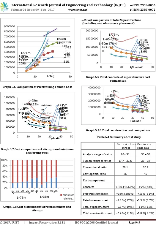
© 2017, IRJET | Impact Factor value: 5.181 | ISO 9001:2008 Certified Journal | Page 949 Graph 5.6 Comparison of Prestressing Tendon Cost
Graph 5.7 Cost comparisons of stirrups and minimum reinforcing steel
Graph 5.8 Cost distributions of reinforcement and stirrups
5.2 Cost comparison of total Superstructure (including cost of concrete placement)
Graph 5.9 Total concrete of superstructure cost comparison
[image:6.595.36.561.38.833.2]Graph 5.10 Total construction cost comparison Table 5.1 Summary of cost study
Cat in situ box-girder Cast in situ solid slab Analysis range of ratios 10 - 35 30 – 50 Typical range of ratios 17.7 - 22.6 22 – 39 Conventional ratio 20.1 30.2 Cost-optimal ratio 25 40 Cost component
Concrete -5.1% (41.55%) -19% (22%) Prestressing tendon +28% (285%) +53% (61%) Reinforcement steel -1.3 %( 17%) -5.3 % (5.7%) Total superstructure -0.6 %( 19%) -11% (11%) Total construction cost -0.4 %( 11%) -5.8 %( 6.2%) 0
1000000 2000000 3000000 4000000 5000000 6000000 7000000 8000000 9000000
0 20 L/d 40 60
L=75m,
285%
L=60m,
223%
L=50m
209%
L=35m
38%
L=25
m
38%
L=30m
61%
L=35m
162%
L=20
m
51%
0 200000 400000 600000 800000 1000000 1200000
0 10 20 30 40 50
L/d ratio
L=60m,
39%
L=50m
31%
L=35m
24%
L=35m
38%
L=30m
61%
L=25m
40%
L=20m
51%
L=75m,
41.55%
L=60m,
39%
L=50m
31%
L=35m
24%
L=35m
38%
L=30m
61%
L=25m
40%
L=20m
51%
minimu
m
reinforc
ement
line
0% 20% 40% 60% 80% 100%
10 15 20 25 30 35 30 35 40 45
minimum reinforc…
L=75m
L=35m
0 5000000 10000000 15000000 20000000
0 10 20 30L/d ratio 40 50
L=75m,
17%
L=60m,17%
L=50m 17%%
L=35m 16
%
L=35m
12%
L=30m
12%
L=25m
9.6%
L=20m
3.6%
0 10000000 20000000 30000000 40000000
0 10 20 30 40 50
L/d ratio
L=75m,
12%
L=60m,
11%
L=50m
9.0%%
L=35m 7.7
%
L=35m
6.1%
L=30m
6.2%
L=25m
5.0%
L=20m
© 2017, IRJET | Impact Factor value: 5.181 | ISO 9001:2008 Certified Journal | Page 950 6.1 Conclusion
Girder-type bridges have commonly been designed using conventional slenderness ratios which have not changed significantly despite recent development in material strengths and construction technologies. This study determines the optimum slenderness ratios for two types of girder bridges constructed with high-strength concrete: cast-in-situ box-girder and solid slab, the ratios are optimized based on material consumption and total construction cost. The results of this thesis are summarized as follows.
A study of 86 constant-depth girder bridges reveals that the typical ranges of slenderness ratios are 17.7 to 22.6 for in-place box-girder, 22 to 39 for cast-in-situ solid slab, and 15.7 to 18.8 for precast segmental box-girder. The study demonstrates that the ratios for cast-in-situ box-girders have not varied significantly from 1958 to 2007. The study also indicates that cast-in-situ solid slabs constructed after 1975 are mostly voided slabs with slenderness ratios below 25 due to the more stringent code requirements in recent years.
REFERENCES:
[1] ‘Miss Bhivgade. R.P.(2001)’ “Analysis and design of prestressed concrete box girder bridge”
[2] ‘Prof. Joseph Ancy, Babu Elsa , Babu Karthika , Lakshmi G, Krishna R Meera, “Analysis And Design Of Railway Over Bridge At Kumaranellur”, International Journal of Civil and Structural Engineering Research, ISSN 2348-7607 (Online)Vol. 2, Issue 2, pp: (124-127), Month: October 2014 - March 2015
[3] ‘Mulesh K. Pathak (M. E. Casad)’ “Performance of RCC Box type Superstructure in Curved bridges” International Journal of Scientific & Engineering Research, Volume 5, Issue 1, January-2014, ISSN 2229-5518
[4] IS: 1343, Indian Standard Code of Practice for Prestressed concrete (2nd Revision), Bureau of
Indian Standards, New Delhi.
[5] IRC : 18-2000, Design Criteria for Prestressed Concrete Road Bridges (Post tensioned concrete) (2nd Revision), Indian Road Congress, New Delhi