DESIGN AND ANALYSIS OF COMPOSITE LEAF SPRING BY USING CATIA
AND ANSYS
Bandi Manasa
1,R.Lokanadham
21 PG Scholar, Mechanical Engineering, Chadalawada Ramanamma Engineering College, Tirupati, Andhra Pradesh, India.
2 Professor, Mechanical Engineering, Chadalawada Ramanamma Engineering College, Tirupati, Andhra Pradesh, India.
---***---Abstract -Leaf spring is a simple form of suspension
spring used to absorb vibrations induced during the motion of a vehicle. The automobile industry has shown increased interest in the replacement of steel leaf spring (55 si 7) with composite leaf spring (e-glass/epoxy) due to high strength, reduction of weight ratio, higher stiffness, high impact energy absorption and lesser stresses.The design of leaf springs are prepared in catia V5R20 and imported in statis structural analysis work bench of ansys 12.1 where finite element analysis (FEA) is performed with different loads.the design constraints are stresses, strains and deflection of different materials steel leaf spring,e-glass/epoxy and jute/e-spring,e-glass/epoxy leaf spring and also comparing the weights of the materials.
KeyWords:CATIA,ANSYS,Steel,E-Glass/Epoxy,Jute/E-Glass/Epoxy.
1.INTRODUCTION
A spring is defined as an elastic body,whose function is to distort when loaded and recover its original shape when the load is removed.Tp apply forces as in brakes,clutches and spring-loaded valve.
2.PRINCIPLES OF LEAF SPRING
The leaf spring arrangements mounted the a single leaf set running parallel to a live axle, but used it both as a suspension link and a spring element in a similar manner to the traditional arrangement. In vehicles with independent suspension and a transverse leaf spring arrangement the leaf is not used to control the wheel's location and acts only as a spring element. In this arrangement double wishbones act to locate the wheel, while a single leaf or leaf set connected to the front or rear sub-frame in the middle of the vehicle and the lower wishbone on each side provides the spring element. In some applications two transverse leaf springs are used on a single axle with each providing separate springing action to each wheel. In the past most transverse leaf springs arrangements used multiple steel elements in a set similar to their traditional longitudinal counterparts, but most modern applications uses a composite (generally fiberglass) mono leaf element.
2.1 Parts of Leaf Spring
Figure 1: Leaf spring of Automobiles
1. Master Leaf
The longest leaf known as main leaf or master leaf has its ends formed in the shape of an eye through which the bolts are passed to secure the spring to its supports
2. Graduated Leaves
The other leaves of the springs are known as graduated leaves. In order to prevent digging in the adjacent leaves.It is usual to provide two full length leaves and the rest graduated leaves.
3.Eye
Usually the eyes, through which the spring is attached to the hanger or shackle, are provided with of bushing of some antifriction of material such as bronze or rubber.
4.Center Bolt
The leaves are held together by means of a band shrunk around them at the centre or by a bolt passing through the centre.
5.Rebound Clip
Rebound clips are placed intermediate positions of the leaf spring. These are joints the master leaf and graduated leaves of the leaf spring.
3. LITERATURE REVIEW
Many early vehicles such as the ford model it used transverse leaf springs on both the front and rear suspension in conjunction with a live axle. In the early 1930s, Dante giocoso developed the fiat tapeline which
International Research Journal of Engineering and Technology (IRJET)
e-ISSN: 2395-0056used transverse steel leaf springs and double wishbones in an independent front suspension. The triumph motorcar company also developed a independent rear suspension with a transverse leaf spring arrangement for their line of small cars in the 1950s. The triumph arrangement, first seen on the 1959 herald was developed in an effort to introduce a inexpensive independent rear suspension. Results were mixed with considerable safety issues surrounding the vehicles tendency to snap into over steer.
Manas patnaik, l.p. Koushik and manoj Mathew [6] has been carried out on a parabolic leaf spring of a mini loader truck. The spring has been analyzed by applying a load of 3800 N and the corresponding values of stress and displacement are computed. In this work, design of experiments has been applied under various has been is configurations of the spring (i.e by varying camber & eye distance). Camber and leaf span of a parabolic leaf spring was found for optimized stress and displacement value using artificial neural networks. Various networks with different architecture were trained and the network giving the best performance was used for optimization.
Bhushan, Deshmukh, Dr. Santosh and B. Jaju int j [2] engg techsci.weight reduction is now the main issue in automobile industries. The paper gives the brief look on the suitability of composite leaf spring on vehicles and their advantages. The objective of the present work is design, analysis and fabrication of mono composite leaf spring. The design constraints are stress and deflections. The finite element analysis is done using ansys software. The attempt has been made to fabricate the explian leaf spring economically than that of conventional leaf spring.
4. METHODOLOGY
Present work is related to the comparative study of “55 si 7 steel and composite leaf spring” component details. The component details is studied and prepared 3-d model in catiya V5R20 software. The component is studied for the operation required to convey the different types of loads on it. Design the component in the required shape and dimensions and analyzed.
Design calculations are carried for the component leaf spring with the help of material properties which are specified by the previous project. Analysis work is carried by importing 3-d model into ansys software. A fem model of leaf spring, only one leaf is created by using ansys processor. The material properties loads and boundary conditions are also specified in the ansys processor.
Analysis work is done by applying loads on the leaf spring then the results such as stress, strain, total deformation are obtained. The results are compared with material properties of the material used for the component. Then we find that results obtained by using fem are within
the material properties. There we find that the componentcan withstand for given loads during operation.
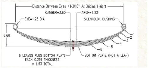
4.1 STANDARD SEMI ELLIPTICAL LEAF SPRING
We have already discussed that the stress in the full length leaves is 50% greater than the stress in the graduated leaves. In order to utilize the material to the best advantage all the leaves should be equally stress.
[image:2.595.308.561.273.389.2]By giving a greater radius of curvature to the full length leaves than graduated leaves before the leaves are assembled to form a spring by doing so a gap or clearance will be left between the leaves.
Figure 2: Standard semi elliptical leaf spring
Distance between eyes = 1100 mm Camber = 96.8 mm
Height = 167.64 mm
For the leaf spring in original form,
Free Camber = 3.60” (factory specification) Spring eye = 1-1/4”diameter(0.625”-radius) Leaf thickness = 7/32”
Number of functional leaves = 6
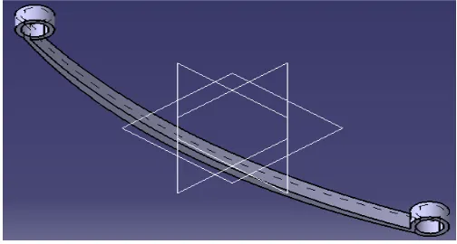
5. DESIGN OF LEAF SPRING IN CATIA V5R20
Start the catia V5R20 software by giving double click on the catia V5R20 icon on the desktop. click the start menu in the menu bar, select mechanical design and click sub menu sketcher. Click the xy plane. Draw the horizontal and vertical axis lines by selecting the infinite line option in the profile tool box. Draw the two lines parallel to the vertical axis line by the infinite line option. Give the distance between the two line according to length of the leaf spring (1050 mm) and arc height at axel seat (170 mm) of the leaf spring requirement by the constraint option in the constraint tool box.
workbench option in the workbench tool box.click the pad option in the sketcher tool box and enter the required length of the leaf spring (56 mm) and finally click ok.
5.1 Design Parameters of Leaf Spring
[image:3.595.310.553.146.333.2]Total length of leaf spring (eye to eye) 1050 mm Arc height at axle seat 170 mm Thickness of leaf spring 6 mm Width of leaf spring 56 mm Outer diameter of eye 50 mm Inner diameter of eye 44 mm
Table 1: Design parameters of leaf spring
Figure 3: Leaf spring designed in catia V5R20
5.2 Design Parameters of composite Leaf Spring
Table 2: Design Parameters of composite leaf spring
6. MODAL ANALYSIS
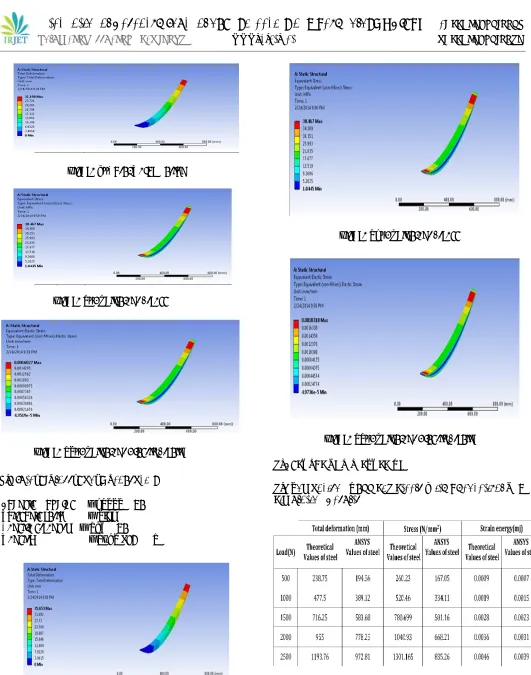
6.1 Steel Leaf spring (55Si 7)
[image:3.595.54.270.165.275.2]Young’s modulus = 190-210 mpa Poisson’s ratio = 0.27-0.30 Tensile strength = 572.3 mpa Density = 1000 kg/m3
[image:3.595.35.287.311.446.2]Figure 5: Total Deformation
[image:3.595.312.557.363.478.2]Figure 6: Equivalent Stress
Figure 7: Equivalent Elastic Strain
6.2 E-Glass/Epoxy Leaf spring
Young’s modulus = 24000 mpa Poisson’s ratio = 0.30 Tensile strength = 205 mpa Density = 1520 kg/mm3
Figure 4: Composite leaf spring designed in catia V5R20
[image:3.595.41.414.517.744.2]Figure 8: Total Deformation
Figure 9: Equivalent Stress
Figure 10: Equivalent Elastic Strain
6.3 Jute/E-Glass/Epoxy Leaf spring
Young’s modulus = 21000 mpa Poisson’s ratio = 0.22 Tensile strength = 185 mpa Density = 1460 kg/mm3
[image:4.595.35.566.32.707.2]Figure 11: Total Deformation
Figure 12: Equivalent Stress
Figure 13: Equivalent Elastic Strain
7. RESULTS AND DISCUSSION
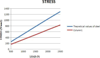
[image:4.595.326.554.289.455.2]7.1 Comparison Of 55 Si 7 Steels With Theoretical And Simulation Results
[image:4.595.309.578.551.699.2]Graph 1: Comparison of different loads with deformation
Graph 2: Comparison of different loads with Stresses
Graph 3: Comparison of different loads with Strain energy
[image:5.595.39.251.266.390.2]7.2 Comparison Between [A](E-Glass/Epoxy) Leaf Spring And [B](Jute/E-Glass/Epoxy)
Table 4: Comparison between E-Glass/epoxy and Jute/ E-Glass/epoxy results
Graph 4: Comparison of different loads with deformation
Graph: 5 Comparison of different loads with Stresses
Graph 6: Comparison of different loads with Strain energy
7.3 Comparison of weights
Graph 7: Comparison of different weights of materials
International Research Journal of Engineering and Technology (IRJET)
e-ISSN: 2395-0056Graph 8: Comparison of different cost of materials
CONCLUSIONS
The 3-D modeling of both steel and hybrid composite materials of leaf spring is done and analyzed a comparative study has been made between composite and steel leaf spring with respect to deflection , strain energy and stresses.
This project work provides optimum output for design parameters (leaf spring thickness and width) of hybrid composite leaf spring by using finite element analysis. Weight can be reduced from in kgs to 2kg if steel leaf spring is replaced by jute/e-Glass/epoxy hybrid composite leaf spring. Weight reduction reduces the fuel consumption of the vehicle.
At various loading conditions, hybrid composite leaf spring is found to have lesser stresses and deflections as compared to conventional steel leaf spring. Jute/e-glass/epoxy hybrid composite has higher elastic strain energy storage capacity than both steel and e-glass/epoxy composite because it has lower young’s modulus and lower density as compared to both. Hence hybrid composite leaf spring can absorb more energy which leads to good comfortable riding.
Jute/e-glass/epoxy hybrid composite leaf spring is found to be more economical than e-glass/epoxy composite leaf spring as the cost of jute fiber is very much less as compared to e-glass fiber and it is abundantly available in nature.
REFERENCES
1) Baviskar a. C., bhamre v. And g., sarode s. S, “ design and analysis of a leaf spring for automobile suspension system”. A review international journal of emerging technology and advanced engineering website: www.ijetae.com (issn 2250-2459, iso 9001:2008 certified journal, volume 3, issue 6, june 2013) pp 407-410.
2) Bhushan, b. Deshmukh and dr. Santosh b. Jaju “ design and analysis of fiber reinforce polymer (frp) leaf spring”. - a review int j engg techsci vol 2(4) 2011,289-291
3) Gulur siddaramanna, shiva shankar and sambagam, “mono composite leaf spring for light weight vehicle – design end joint analysis and testing” issn 1392–1320 materials science (medžiagotyra). Vol. 12, no. 3. 2006.
4) Jadhav mahesh v, zoman digambar b, y r kharde and r r kharde, “performance analysis of two mono leaf spring used for maruti 800 vehicle”. International journal of innovative technology and exploring engineering (ijitee) issn: 2278-3075, volume-2, issue-1, december 2012.
5) Kumarkrishna and aggarwal m.l, “a finite element approach for analysis of a multi leaf spring using cae tools” research journal of recent sciences issn 2277-2502 vol. 1(2), 92-96, feb. (2012) res.j.recent sci.
6) Shishay and amare gebremeskel, “design, simulation, and prototyping of single composite leaf spring for light weight vehicle”.global journal of researches in engineering mechanical and mechanics engineering volume 12 issue 7 version 1.0 year 2012 type: double blind peer reviewed international research journal publisher: global journals inc. (usa) online issn: 2249-4596 print issn:0975-5861.