TM
A Structure from Motion Approach using Constrained Deformable Models and Appearance Prediction
Sing Bing Kang
CRL 97/6
Cambridge Research Laboratory
The Cambridge Research Laboratory was founded in 1987 to advance the state of the art in both core computing and human-computer interaction, and to use the knowledge so gained to support the Company’s corporate objectives. We believe this is best accomplished through interconnected pur-suits in technology creation, advanced systems engineering, and business development. We are ac-tively investigating scalable computing; mobile computing; vision-based human and scene sensing; speech interaction; computer-animated synthetic persona; intelligent information appliances; and the capture, coding, storage, indexing, retrieval, decoding, and rendering of multimedia data. We recognize and embrace a technology creation model which is characterized by three major phases:
Freedom: The life blood of the Laboratory comes from the observations and imaginations of our
research staff. It is here that challenging research problems are uncovered (through discussions with customers, through interactions with others in the Corporation, through other professional interac-tions, through reading, and the like) or that new ideas are born. For any such problem or idea, this phase culminates in the nucleation of a project team around a well articulated central research question and the outlining of a research plan.
Focus: Once a team is formed, we aggressively pursue the creation of new technology based on
the plan. This may involve direct collaboration with other technical professionals inside and outside the Corporation. This phase culminates in the demonstrable creation of new technology which may take any of a number of forms - a journal article, a technical talk, a working prototype, a patent application, or some combination of these. The research team is typically augmented with other resident professionals—engineering and business development—who work as integral members of the core team to prepare preliminary plans for how best to leverage this new knowledge, either through internal transfer of technology or through other means.
Follow-through: We actively pursue taking the best technologies to the marketplace. For those
opportunities which are not immediately transferred internally and where the team has identified a significant opportunity, the business development and engineering staff will lead early-stage com-mercial development, often in conjunction with members of the research staff. While the value to the Corporation of taking these new ideas to the market is clear, it also has a significant positive im-pact on our future research work by providing the means to understand intimately the problems and opportunities in the market and to more fully exercise our ideas and concepts in real-world settings.
Throughout this process, communicating our understanding is a critical part of what we do, and participating in the larger technical community—through the publication of refereed journal articles and the presentation of our ideas at conferences–is essential. Our technical report series supports and facilitates broad and early dissemination of our work. We welcome your feedback on its effec-tiveness.
A Structure from Motion Approach using Constrained Deformable
Models and Appearance Prediction
Sing Bing Kang
October 1997
Abstract
In this technical report, we address the problem of recovering 3-D models from sequences of uncalibrated images with unknown correspondence. To that end, we integrate tracking, structure from motion with geometric constraints, and use of deformable 3-D models in a single framework. The key to making the proposed approach work is the use of appearance-based model matching and refinement.
c Digital Equipment Corporation, 1997
This work may not be copied or reproduced in whole or in part for any commercial purpose. Per-mission to copy in whole or in part without payment of fee is granted for nonprofit educational and research purposes provided that all such whole or partial copies include the following: a notice that such copying is by permission of the Cambridge Research Laboratory of Digital Equipment Corpo-ration in Cambridge, Massachusetts; an acknowledgment of the authors and individual contributors to the work; and all applicable portions of the copyright notice. Copying, reproducing, or repub-lishing for any other purpose shall require a license with payment of fee to the Cambridge Research Laboratory. All rights reserved.
CRL Technical reports are available on the CRL’s web page at http://www.crl.research.digital.com.
Digital Equipment Corporation Cambridge Research Laboratory One Kendall Square, Building 700
CONTENTS i
Contents
1 Introduction 1
1.1 Prior work . . . 1
1.2 Organization . . . 3
2 General approach 3 2.1 Tracking by spline-based registration . . . 4
2.2 General structure from motion . . . 6
2.3 Least-squares minimization with geometric constraints . . . 8
2.4 Generating predicted appearance . . . 10
3 Application: Mapping new faces to 3-D DECface 10 3.1 DECface . . . 10
3.2 Mapping faces using one input image . . . 11
3.3 Mapping faces using three input images . . . 12
4 Discussion 13
ii LIST OF FIGURES
List of Figures
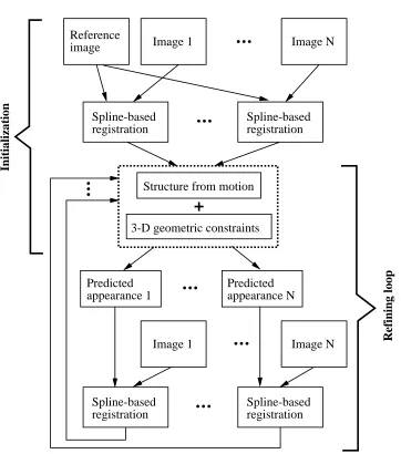
1 General approach of appearance-based constrained structure from motion (AbCSfm). 5 2 Displacement spline: the spline control verticesf
(^
u
j
v
^
j)
gare shown as circles ( )
and the pixel displacementsf
(
u
iv
i)
gare shown as pluses (
+
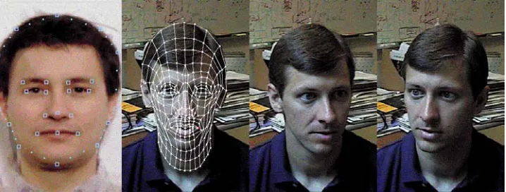
) [22]. . . 63 Reconfigured facial geometry on the face image. Notice the close alignment of the nodes around the eyes, mouth, chin and face margins. . . 11
4 Initial state. The generic face whose DECface topology is known is shown at the left most. The other three images are the input images, with the reference image being the second image from the left. . . 12
5 State immediately after performing spline-based registration for the second and third images in the sequence. . . 13
6 Intermediate predicted facial appearance for the two non-reference images. . . 14
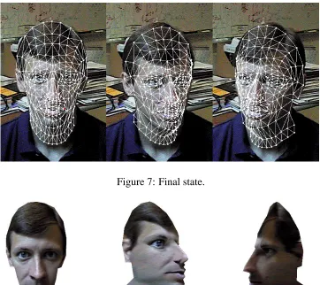
7 Final state. . . 14
8 Appearance of final 3-D face model at various poses. . . 14
9 Side views of original (left) and deformed (right) 3-D meshes for the face in Figure 4. 15 10 Appearance of final 3-D face model at various poses (with no geometric con-straints, apart from line-of-sight). . . 15
11 Input images of another face. . . 15
12 Appearance of final 3-D face model at various poses (from input images shown in Figure 11. . . 16
1
1 Introduction
The classical approach to recovering 3-D structure from a sequence of images is to calibrate the camera, track the features across the sequence, and then apply stereo techniques using the tracked features. More recent techniques allow 3-D structures to be recovered without explicit camera calibration. Nevertheless, the processes of feature tracking and structure from motion are almost always separate.
In this technical report, we propose an approach that integrates tracking, structure from mo-tion with geometric constraints, and use of deformable 3-D models in a single framework. The input image sequence is assumed uncalibrated, and the image correspondences are also assumed not known. The key to making the proposed approach work is the use of appearance-based model matching and refinement. Another distinguishing feature of this approach is that feature corre-spondences are not statically determined; they may “drift” over time according to how well they satisfy both local image similarity and 3-D geometric constraints.
This appearance-based constrained structure from motion (AbCSfm) approach is especially useful in recovering shapes of objects whose general structure is known but which may have little discernable texture in significant parts of their surfaces. A good example of such an object is the human face, where there is usually a significant amount of relatively untextured regions (espe-cially if there is little facial hair) and where the facial structure is known. We applied the proposed approach to 3-D face modeling from multiple images to create new 3-D faces for DECface, a syn-thetic talking head developed at Cambridge Research Laboratory, Digital Equipment Corporation. The DECface model comprises a collection of 3-D triangular and rectangular facets, with nodes as vertices. In recovering the DECface model, we assume that the sequence of images are taken with a camera with unknown camera focal length and extrinsic parameters (i.e., camera pose).
In our current implementation, we use the frontal shot of the face as the reference image and im-pose a line-of-sight constraint of 3-D facial nodes using this reference image. We also constrained 3-D model deformation by minimizing an objective function that trade-off minimal change in local curvature and node position with fit to predicted point correspondences and face appearance.
1.1 Prior work
2 1 INTRODUCTION
initially extracted correspondence to estimate the epipolar geometry using a robust estimator. The computed epipolar geometry is then used to recover more correspondences as in classical stereo matching.
Virtually all stereo approaches assume fixed disparity throughout once it has been established, e.g., through a separate feature tracker or image registration technique. Most techniques assume that the camera parameters, intrinsic and extrinsic, are known. Our proposed method integrates the tracker with structure and motion recovery, and does not assume that the focal length is known. In theory, for general camera motion with constant intrinsic parameters, three views are sufficient to recover structure, camera motion, and all five camera intrinsic parameters [7, 20]. For algorithmic stability, we assume only one unknown intrinsic camera parameter, namely the focal length. The aspect ratio is assumed to be unity, the image skew to be insignificant, and the principal point to be coincident with the center of the image.
The approaches specific to face modeling can be partitioned into two categories based on the input, namely range and image data, and images only. In an approach that uses both range and image data, Lee et al. [11] use dense 3-D data from Cyberware Color DigitizerTM, and apply 3-D feature-based matching (for facial features such as the nose, chin, ears, eyes) to initialize their 3-D adaptable facial mesh. This facial mesh is subsequently augmented with a dynamic model of facial tissue controlled by facial muscles. Kang et al. [10] use as input both range image and corresponding color image of the face. They use color-based 2-D facial feature detection methods to locate the eyes, eyebrows, and mouth. The feature detection involve computing edges in color space followed by contour extraction and smoothing by dilation and shrinking.
The simpliest case of techniques using only images as input involves only two orthogonal views (namely, the front and side views) of the face. Extraction of 3-D face model would then entail profile analysis, identification of facial features from contours, and adjustment of a 3-D face template through interpolation [1, 8].
Lengagne et al. use a calibrated stereo pair and use the dense disparity map computed through an interpolation technique [4]. In their approach, the 3-D deformation of the face model is guided by differential features that have high curvature values (such as the nose and eye orbits).
1.2 Organization 3
using recursive Kalman filtering [9]. The deformation of the face shape is constrained by linear subspace of eigenvectors as a result of Singular Value Decomposition (SVD) of sample face shapes. In this case, the whole face is not tracked. In a more general approach, Fua and Leclerc [5] reconstruct both shape and reflectance properties of surfaces from multiple images. The surface shape is initialized by conventional stereo, and is deformed while minimizing an objective function that is a weighted sum of stereo, shading, and smoothness constraints.
1.2 Organization
In section 2, we describe in detail our approach which we call appearance-based constrained
structure from motion (AbCSfm). This approach enables 3-D models to be extracted from multiple
images despite initially unknown feature correspondences. It is based on image-based registration that is guided by predicted 3-D image appearance and a structure from motion algorithm. To illustrate the proposed approach, we then describe an application that uses AbCSfm to recover 3-D facial models from multiple images in section 3.1. Discussion of the method and a possible variant of it is given in section 4, with a summary subsequently provided.
2 General approach
We have developed an approach that allows us to recover a 3-D model from initially unknown point correspondence and an approximate 3-D template. We call this approach appearance-based
constrained structure from motion (AbCSfm). The components of AbCSfm, as shown in Figure 1,
are
Image registration (spline-based registration in our case [22]
Structure from motion (iterative Levenberg-Marquardt batch approach [23]
Appearance prediction (simple texture resampling [28]). The predicted appearance is
com-puted based on current image point correspondences and structure from motion estimates, and is used to refine image registration.
4 2 GENERAL APPROACH
1. Appearance prediction
In this step, for each image other than the reference image, the appearance of the 3-D model given the camera pose and intrinsic parameters is computed and projected onto a new image.
2. Spline-based image registration
The predicted image is registered with the actual image to refine the point correspondences.
3. Structure from motion
Using the refined point correspondences, estimate the new (usually better) estimates of the camera pose and intrinsic parameters, as well as 3-D model shape.
The use of appearance-based strategy is important as it accounts for not only occlusions, but also perspective distortion due to changes in object pose. In contrast to Lowe’s approach [13] which uses edges, we use whole predicted images.
2.1 Tracking by spline-based registration
In the spline-based registration framework [22, 24], a new image
I
2 is registered to an initial baseimage
I
1 using a sum of squared differences formulaE
(
fu
i
v
i g) =
X
i
I
2(
x
i+
u
iy
i+
v
i)
;
I
1(
x
iy
i)]
2 (1)
where thef
u
iv
ig’s are the per-pixel flow estimates.
In this registration technique, the flow estimatesf
u
iv
igare represented using two-dimensional splines controlled by a smaller number of displacement estimates
u
^
j and^
v
j which lie on a coarser spline control grid (Figure 2). This is in contrast to representing them as completely independentquantities (and thus having an underconstrained problem). The value for the displacement at a pixel
i
can be written as0 @
u
(
x
i
y
i)
v
(
x
iy
i)
1 A
=
X
j
B
j(
x
iy
i)
0 @
u
^
j
^
v
j 1 A or 0 @u
iv
i 1 A=
X jw
ij 0 @u
^
j
^
v
j1
A (2)
where the
B
j(
x y
)
are called the basis functions and are only non-zero over a small interval (finite support). Thew
ij=
B
j(
x
iy
i)
are called weights to emphasize that the(
u
iv
i)
are known linearcombinations of the
(^
u
jv
^
j)
.In the current implementation, the spline control grid is a regular subsampling of the pixel grid,
^
x
j=
mx
i,y
^
j=
my
i, so that each set ofm
2.1 Tracking by spline-based registration 5
Reference
image Image 1 Image N
Spline-based registration
Spline-based registration
Structure from motion
3-D geometric constraints
Image 1 Image N
Spline-based registration
Spline-based registration
Initialization
Refining loop
Predicted appearance 1
[image:11.612.131.493.170.580.2]Predicted appearance N
6 2 GENERAL APPROACH
+
+
+
+
+
+
+
+
+
+
+
+
+
+
+
+
+
+
+
+
+
+
+
+
+
+
+
+
+
+
+
+
+
+
+
+
+
+
+
+
+
+
+
+
+
+
+
+
e e e e(^
u
j^
v
j)
[image:12.612.197.415.102.264.2](
u
iv
i)
Figure 2: Displacement spline: the spline control verticesf
(^
u
jv
^
j)
gare shown as circles ( ) and
the pixel displacementsf
(
u
iv
i)
gare shown as pluses (
+
) [22].bilinear basis functions, i.e.,
B
j(
x y
) = max((1
;j
x
;x
^
jj
=m
)(1
;jy
;y
^
jj
=m
) 0)
(see [22] fora discussion of other possible bases). The local spline-based flow parameters are recovered using a variant of the Levenberg-Marquardt iterative non-linear minimization technique [17].
We also modified (2) to include the weights
m
ijassociated with a mask as follows:0 @
u
iv
i 1 A=
X jm
ijw
ij0 @
u
^
j
^
v
j1
A (3)
where
m
ij= 1
or 0 if the corresponding pixel is in the object or background area respectively.This is necessary to prevent registration of the background areas influencing registration of the projected model areas across images.
m
ij can also assume values between 0 and 1, especiallyduring the hierarchical search where the images are subsampled and the intensities averaged.
2.2 General structure from motion
The formulation of recovering structure from motion is based on that of [23]. Essentially, we are trying to recover a set of 3-D structure parameters
p
iand time-varying motion parametersT
j from
a set of observed image features
u
ij. The general equation linking a 2D image feature locationu
ijin frame
j
to its 3-D positionp
i (i
is the track index) isu
ij=
P
T
(K)2.2 General structure from motion 7
where the perspective projection transformationP
()
is applied to a cascaded series of rigidtrans-formation
T
(k)j . Each transformation is in turn defined by
T
(k)j
x
=
R
(k)
j
x
+
t
(k)
j (5)
where
R
(k) is a rotation matrix andt
( k)j is a translation applied after the rotation. Within each of
the cascaded transforms, the motion parameters may be time-varying (the
j
subscript is present) or fixed (the subscript is dropped).The general camera-centered perspective projection equation is
0 @
u
v
1 A=
P1 0 B B @x
y
z
1 C C A 0 @fx+ y z
+
u
0 rfyz
+
v
0 1A (6)
where
f
is a product of the focal length of the camera and the pixel array scale factor,r
is the image aspect ratio,is the image skew, and(
u
0v
0)
is the principal point. In theory, for general camera motion with constant intrinsic parameters, three views are sufficient to recover structure, camera motion, and all five camera intrinsic parameters [7, 20]. For stability, we assume only one intrinsic camera parameters matter, namely the focal length (the aspect ratio is assumed to be unity).An alternative object-centered formulation (a more general version of [23]) which we use is
0 @
u
v
1 A=
P2 0 B B @x
y
z
1 C C A 0 @sx+ y
1+z
+
u
0rsy
1+z
+
v
01 A
=
0 @ sx 1+z rsy 1+z 1 A (7)with the reasonable assumption that
= 0
and(
u
0v
0) = (0 0)
. Here, we assume that the(
x y z
)
coordinates before projection are with respect to a reference frame that has been displacedaway from the camera by a distance
t
z along the optical axis,1 with
s
=
f=t
z and
= 1
=t
z. Theprojection parameter
s
can be interpreted as a scale factor andas a perspective distortion factor. Our alternative perspective formulation results in a more robust recovery of camera parameters under weak perspective, where1
, and assuming(
u
0v
0)
(0 0)
and0
, we haveP
(
x y z
)
T
(
sx rsy
)
T
. This is because
s
andrs
can be much more reliably recovered than, in comparison with the old formulation wheref
andt
z are very highly correlated.1If we wish, we can view
t z as the
z component of the original global translation which is absorbed into the
8 2 GENERAL APPROACH
2.3 Least-squares minimization with geometric constraints
The Levenberg-Marquardt algorithm [17] is used to solve for the structure and motion parameters. Without the geometric constraints, formulation is exactly that of [23]. We are, instead, trying to minimize
Eall
(
a
) =
Esfm(
a
) +
Egeom(
a
)
(8)where
Esfm
(
a
) =
X i X jc
ij ju
ij;P
(
a
ij)
j
2 (9)
is the usual structure from motion objective function that minimizes deviation from observed point feature positions.P
()
is given in (4), anda
ij=
p
T im
T jm
T g T (10)is the vector of structure and motion parameters which determine the image of point
i
in framej
. The vectora
contains all of the unknown structure and motion parameters, including the 3-D pointsp
i, the time-dependent motion parametersm
j, and the global motion/calibration parametersm
g. The weightc
ij in (9) describes our confidence in measurementu
ij, and is normally set to theinverse variance
;2ij . Implementational details are given in [23]. In our case, we set
c
ij to be a
value proportional to the least amount of local texture indicated by the minimum eigenvalue of the local Hessian. The local Hessian
H
is given byH
=
2 4 P WI
2 x P WI
xI
y PW
I
xI
yP W
I
2 y 3 5 (11)Wbeing the local window centered at
(
x y
)
and(
I
x
I
y)
is the intensity gradient at(
x y
)
. Ife
minijis the minimum eigenvalue at point
i
in framej
, thenc
ij=
e
minijmax
ije
minij(12)
This is particularly important in the case of face model recovery because of the possible lack of texture on parts of the face, such as the cheeks and forehead areas. Using this metric for
c
ijdownplays the importance of points on these relatively untextured areas (see, for example, [18, 24]). To account for occlusions,
c
ij is set to zero if the corresponding point is predicted to behidden.
The other term in (8) is
2.3 Least-squares minimization with geometric constraints 9
which is the additional geometric constraints that reduces the deformation of the template or refer-ence 3-D model. The quantities with the superscript 0 refers to the referrefer-ence 3-D model that is to be deformed.
h
i is the perpendicular distance of pointp
i to the plane passing through its nearestneighbors (three in our case). In other words, if i is the best fit plane of the neighbor points of
p
i,and
p
n
^
i
=
d
iis the equation of i, thenh
i=
p
in
^
i;
d
i (14)
i is the weight associated to the preservation of local height (in a sense, preserving curvature),and
i is the weight associated with the preservation of the reference 3-D position. The weightscan be made to vary from node to node, or made constant across all nodes, as in our case. The Levenberg-Marquardt algorithm first forms the approximate Hessian matrix
A
=
X i 2 4 X jc
ij@
P(
a
ij
)
@a
!T
@
P(
a
ij
)
@a
+
B
(
i)
3
5 (15)
where
B
(
i)
is a matrix which is zero everywhere except at the diagonal entries corresponding tothe
i
th 3-D point. The weighted gradient vector isb
=
Xi 2 4 ; X j
c
ij@
P(
a
ij
)
@a
!T
e
ij+
g
i 35 (16)
where
g
i= (0
:::p
0T i:::
0)
T, and
p
0i
=
i(
h
i;
h
0 i)
@h
i@p
i !T+
i(
p
i ;p
0
i
)
=
i(
h
i;
h
0
i
) ^
n
i
+
i(
p
i ;p
0
i
)
(17)
from (14) and using the simplifying assumption that each node position is independent of its neigh-bors (not strictly true).
e
ij=
u
ij;P
(
a
ij
)
is the image plane error of pointi
in framej
.Given a current estimate of
a
, it computes an incrementa
towards the local minimum by solving(
A
+
I
)
a
=
;b
(18)where is a stabilizing factor which varies over time [17].
10 3 APPLICATION: MAPPING NEW FACES TO 3-D DECFACE
2.4 Generating predicted appearance
It is relatively easy to render the model given the 3-D surface model (with its facets and vertices) and its position and orientation. The object facets are sorted in order of decreasing depth relative to the camera, and then rendered by texture-mapping the facets in the same order. The rendering technique used in our work is a standard technique in computer graphics, and can be found in [28]. A 3-D model that is a good candidate for our proposed approach is the human face model. Its structure is known and using conventional stereo techniques are not very reliable because the human face usually has significant portions of relatively untextured regions.
3 Application: Mapping new faces to 3-D DECface
3.1 DECface
DECface is a system that facilitates the development of applications requiring a real-time lip-synchronized synthetic face [26]. Originally based on the X Window System and the audio facili-ties of DECtalk and AF [12], DECface has been built with a simple interface protocol to support the development of face-related applications. The fundamental components of DECface are software speech synthesis, AF (AudioFile), and face modeling.
Of particular importance to us is the face modeling component. It involves texture-mapping frontal view face images (synthetic or real) onto a correctly-shaped wireframe.
Topologies for facial synthesis are typically created from explicit 3D polygons [15]. For sim-plicity, we construct a simple 2D representation of the full frontal view because, for the most part, personal interactions occur face-to-face. This model consists of 200 polygons of which 50 rep-resent the mouth and an additional 20 reprep-resent the teeth (Figure 3). The jaw nodes are moved vertically as a function of displacement of the corners of the mouth [3]. The lower teeth are dis-placed along with the lower jaw. Eyelids are created from a double set of nodes describing the upper lid, such that as they move, the lids close.
The canonical representation is originally mapped onto the individual’s image mostly by hand. This requires the careful placement of key nodes to certain locations, as illustrated in Figure 3 in particular, the corners of the lips and eyes, the placement of the chin and eyebrows, as well as the overall margins of the face.
3.2 Mapping faces using one input image 11
Figure 3: Reconfigured facial geometry on the face image. Notice the close alignment of the nodes around the eyes, mouth, chin and face margins.
types can be described as a geometric deformation function of which the linear muscle has the simplest derivation (for more details see [25]).
DECface is currently being used as a visual and audio feedback mechanism for the Smart Kiosk project at Cambridge Research Lab, Digital Equipment Corp. [27]. The Smart Kiosk can be considered as an enhanced version of the Automatic Teller Machine, with the added capability of being able to interact with the user through body tracking, and gesture and speech recognition. DECface is used to personalize the interaction between the Smark Kiosk and the user. This ob-jective is achieved partly by its ability to communicate its focus of attention to the user population through the gaze behavior of eye contact.
3.2 Mapping faces using one input image
12 3 APPLICATION: MAPPING NEW FACES TO 3-D DECFACE
Figure 4: Initial state. The generic face whose DECface topology is known is shown at the left most. The other three images are the input images, with the reference image being the second image from the left.
facial features such as the eyes, mouth, and face profile.
Because only one face input image is used, to generate the appropriate 3-D version of DECface, the canonical height distribution is preserved. This is, however, not always desirable, especially since many human faces have significantly different facial shapes. As a result, to preserve as much as possible the correct shape, we use three input images, each showing a different pose of the face, with one showing the frontal face pose. It is possible, of course, to use two or more than three images to achieve the same goal.
3.3 Mapping faces using three input images
In our work, we use three images of the face at different orientations, with one of them at a frontal pose and used as the reference image. As before, we assume all camera parameters, intrinsic and extrinsic, not known (except that the aspect ratio is one, the image skew is zero, and the principal point is at the image center). We also assume that the point correspondences between the generic face and the reference face has been done as in described in the previous section. This is the same as assuming that the reference shape of the model has been initialized. Note, however, that the point correspondences across the image sequence are not known.
We set both
i and i in (13) to 0.25. As mentioned before, the feature track finetuning step13
Figure 5: State immediately after performing spline-based registration for the second and third images in the sequence.
An example is shown in Figures 4-8. A comparison between the original 3-D face model and the deformed 3-D face model is shown in Figure 9. As can be seen, the resulting 3-D face has been horizontally stretched somewhat. If the geometric constraints are not imposed (except for just the simple line-of-sight constraint), then the resulting 3-D face model is quite badly deformed, as seen from Figure 10.
The input images of another face is shown in Figure 11. The resulting face model rendered at three different viewpoints is displayed in Figure 12. As can be seen from the side-by-side visual comparison of the 3-D face models prior to and after deformation (Figure 13), the 3-D model has been again stretched horizontally. In addition, the shape of the forehead is made rounder.
4 Discussion
The algorithm may easily fail if the change in object appearance across image sequence is too drastic from one frame to another. In our application of 3-D face modeling, it tolerates face rotation up to about 15
.
A variant of the method would involve the direct incorporation of the optic flow term into the objective function (8) to give
14 4 DISCUSSION
Figure 6: Intermediate predicted facial appearance for the two non-reference images.
[image:20.612.161.257.111.257.2]Figure 7: Final state.
[image:20.612.124.486.297.619.2]15
[image:21.612.139.479.318.448.2]Figure 9: Side views of original (left) and deformed (right) 3-D meshes for the face in Figure 4.
Figure 10: Appearance of final 3-D face model at various poses (with no geometric constraints, apart from line-of-sight).
[image:21.612.123.455.516.650.2]16 4 DISCUSSION
Figure 12: Appearance of final 3-D face model at various poses (from input images shown in Figure 11.
[image:22.612.208.405.458.601.2]17
where
Eow
(
u
) =
Xi X
j>1
ijj
I
1(
u
i1)
;
I
j(
u
ij)
j
2 (20)
with
I
j(
u
ij)
being the intensity (or color) atu
i on framej
, andij is the weight associated withthe point
u
ij. Note that in our particular application of facial model recovery, since the first frameis the reference frame,
u
i1 is kept constant throughout.One problem with directly embedding this term in the structure from motion module is that the flow error term is local and thus unable to account for large motions. It would either require that the initial model pose be quite close to the true model pose, or the addition of a hierarchical scheme similar to that implemented in the spline-based registration method. Otherwise, the system is likely to have better convergence properties if the tracking is performed outside the structure from motion loop. In the current implementation, while having the small perturbations of the model pose would be desirable from the computational point of view (but not from the accuracy point of view), this is not a requirement.
In addition, using the flow error term directly may not be efficient from the computational point of view. This is because at every iteration and incremental step, a new predicted appearance has to be computed. This operation is rather computationally expensive, especially if the size of the projected model is large. Having the tracking module only loosely coupled with structure from motion results in fewer number of iterations in computing the predicted object appearance. Finally, there is the non-trivial question of assigning the weights
ij relative to the structure from motionand geometric constraint related weights.
Geometric constraints on the face deformation in other forms can also be used. An example would be to use the most dominant few deformation vectors based on SVD analysis of multiple training 3-D faces [9]. A similar approach would be to apply nodal analysis on the multiple training 3-D faces [16, 6] to extract common and permissible deformations in terms of nonrigid modes.
5 Summary
We have described an algorithm called appearance-based constrained structure from motion (AbCSfm) that allows 3-D models to be extracted directly from a sequence of uncalibrated images. It is not necessary to precompute feature correspondences across the image sequence. The algorithm dy-namically determines the feature correspondences, estimates the structure and camera motion, and uses them to predict the object appearance in order to refine the feature correspondences.
18 REFERENCES
results have shown the algorithm to be robust and have good convergence properties.
Acknowledgments
I would like to thank Michael Jones and Rebecca Hwa for “lending” their faces.
References
[1] T. Akimoto, Y. Suenaga, and R. S. Wallace. Automatic creation of 3D facial models. IEEE
Computer Graphics and Applications, pages 16–22, September 1993.
[2] D. DeCarlo and D. Metaxas. The integration of optical flow and deformable models with ap-plications to human face shape and motion estimation. In IEEE Computer Society Conference
on Computer Vision and Pattern Recognition (CVPR’96), pages 231–238, San Francisco, CA,
June 1996. IEEE Computer Society.
[3] V. Fromkin. Lip positions in American English vowels. Language and Speech, 7(3):215–225, 1964.
[4] P. Fua. A parallel stereo algorithm that produces dense depth maps and preserves image features. Machine Vision and Applications, 6:35–49, 1993.
[5] P. Fua and Y. G. Leclerc. Object-centered surface reconstruction: Combining multi-image stereo and shading. International Journal of Computer Vision, 16(1):35–56, September 1995.
[6] J. P. Gourret and J. Khamlichi. A model for compression and classification of face data structures. Computers and Graphics, 20(6):863–879, 1996.
[7] A. Heyden and K. Astrom. Euclidean reconstruction from constant intrinsic parameters. In
Proc.s 13th International Conference on Pattern Recognition, pages 339–343, 1996.
[8] Horace H. S. Ip and L. Yin. Constructing a 3D individualized head model from two orthogo-nal views. The Visual Computer, 12(5):254–266, 1996.
REFERENCES 19
[10] C.-Y. Kang, Y.-S. Chen, and W.-H. Hsu. Automatic approach to mapping a lifelike 2.5D human face. Image and Vision Computing, 12(1):5–14, Jan./Feb. 1994.
[11] Y. Lee, D. Terzopoulos, and K. Waters. Realistic modeling for facial animation. Computer
Graphics (SIGGRAPH’95), pages 55–62, August 1995.
[12] T. M. Levergood, A. C. Payne, J. Gettys, G. W. Treese, and L. C. Steward. AudioFile: A network-transparent system for distributed audio applications. Technical Report 93/8, Digital Equipment Corporation, Cambridge Research Lab, 1993.
[13] D. G. Lowe. Perceptual Organization and Visual Recognition. Kluwer Academic Publishers, Boston, Massachusetts, 1985.
[14] M. Okutomi and T. Kanade. A multiple baseline stereo. IEEE Transactions on Pattern
Analysis and Machine Intelligence, 15(4):353–363, April 1993.
[15] F.I. Parke. State of the art in facial animation. ACM SIGGRAPH Course Notes, 26, 1990.
[16] A. Pentland and S. Sclaroff. Closed-form solutions for physically-based shape modeling and recognition. IEEE Transactions on Pattern Analysis and Machine Intelligence, 13(7):715– 729, July 1991.
[17] W. H. Press, B. P. Flannery, S. A. Teukolsky, and W. T. Vetterling. Numerical Recipes in C:
The Art of Scientific Computing. Cambridge University Press, Cambridge, England, second
edition, 1992.
[18] J. Shi and C. Tomasi. Good features to track. In IEEE Computer Society Conference on
Computer Vision and Pattern Recognition (CVPR’94), pages 593–600, Seattle, Washington,
June 1994. IEEE Computer Society.
[19] G. Stein. Model-based brightness constraints: On direct estimation of structure and motion. In Conference on Computer Vision and Pattern Recognition, pages 400–406, San Juan, Puerto Rico, June 1997.
[20] P. Sturm. Critical motion sequences for monocular self-calibration and uncalibrated Eu-clidean reconstruction. In IEEE Computer Society Conference on Computer Vision and
Pat-tern Recognition (CVPR’97), pages 1100–1105, Puerto Rico, June 1997. IEEE Computer
20 REFERENCES
[21] R. Szeliski. Shape from rotation. In IEEE Computer Society Conference on Computer
Vi-sion and Pattern Recognition (CVPR’91), pages 625–630, Maui, Hawaii, June 1991. IEEE
Computer Society Press.
[22] R. Szeliski and J. Coughlan. Hierarchical spline-based image registration. In IEEE Computer
Society Conference on Computer Vision and Pattern Recognition (CVPR’94), pages 194–201,
Seattle, Washington, June 1994. IEEE Computer Society.
[23] R. Szeliski and S. B. Kang. Recovering 3D shape and motion from image streams using non-linear least squares. Journal of Visual Communication and Image Representation, 5(1):10–28, March 1994.
[24] R. Szeliski, S. B. Kang, and H.-Y. Shum. A parallel feature tracker for extended image sequences. In IEEE International Symposium on Computer Vision, pages 241–246, Coral Gables, Florida, November 1995.
[25] K. Waters. A muscle model for animating three-dimensional facial expressions. Computer
Graphics (SIGGRAPH’87), 21(4):17–24, July 1987.
[26] K. Waters and T. Levergood. DECface: A system for synthetic face applications. Multimedia
Tools and Applications, 1:349–366, 1995.
[27] K. Waters, J. Rehg, M. Loughlin, S. B. Kang, and D. Terzopoulos. Visual sensing of humans for active public interfaces. In Workshop on Computer Vision in Man-machine Interfaces, Cambridge, UK, April 1996.
[28] A. Watt. Fundamentals of Three-dimensional Computer Graphics. Addison Wesley, 1990.
[29] G. Xu and Z. Zhang. Epipolar Geometry in Stereo, Motion and Object Recognition. Kluwer Academic Publishers, September 1996.
[30] Y. Z. Zheng. Acquiring 3-D models from sequences of contours. IEEE Transactions on
TM
A
Structure
fr
om
Motion
Appr
oac
h
using
Constrained
Def
ormab
le
Models
and
Appearance
Prediction
Sing
Bing
Kang
CRL
97/6
October
![Figure 2: Displacement spline: the spline control verticesfthe pixel displacements�u�j�v�j�g are shown as circles (�) andf�ui�vi�g are shown as pluses (�) [22].](https://thumb-us.123doks.com/thumbv2/123dok_us/8990912.968576/12.612.197.415.102.264/figure-displacement-spline-spline-control-verticesfthe-displacements-circles.webp)