Gf'
"JI
(tJJ () (J1\
,,-J.,
l." t ·JRESEARCH, INC.
CRAV X-MP AND CRAV-1®
COMPUTER SYSTEMS
1/0 SUBSYSTEM (lOS)
OPERATOR'S GUIDE
RECORD OF REVISION
~'--I=:. ~~
... _.1
'SUiW
TRESEARCH, INC, PUBLICATION NUMBER SG-OOSI
Each time this manual il revised and reprinted, all cheAl/es issued against the previous version In the form of change packets are incorporated into the new version and the new version IS assigned an alphabetic level. Between reprints, changes may be issued against the current version in the form of change packets. Each change packet is assigned a numeric deSignator, starting with 0-' for the first change packet of eech revilion level.
Every page changed by e reprint or by a chenge packet has the revision level and change packet number In the lower righthand corner. Change. to pert of 8 page are noted by a change bar along the margin of the page. A change bar in the margin opposite the page number indicates that the entire page is new; a dot in the same place indicates that information has been moved from one page to another, but has not otherwise changed.
Request. for copies of Cray Rllsearch, Inc. publications and comments about these publications should be directed to: CRAY RESEARCH, INC.,
1440 Northland Drive,
Mendota Heights, Minnesota 55120
Revision Description
November, 1980 - Original printing.
A June, 1981 - This printing represents a major rewrite and reorganization. It supports the 1.10 version of the station. The MONITOR station command and a number of new Kernel
commands have been added. Several appendixes have been added including Appendix F which describes the parameter file editor and the file utilities. Also, to provide conformity of
terminology among station manuals, the term master operator station replaces system operator station. Changes are not noted by change bars. All previous printings are obsolete.
B June, 1982 - Rewrite. This printing supports the 1.11 version of the station and includes online tape information and new Kernel commands. It also includes new station command and message display information. Appendixes G (Kernel halt error codes), H (interactive station commands), and I (tape mount
request operation) have been added and Appendix B has been reorganized.
C May, 1983 - Rewrite. In accordance with the 1.12 version of the station, this printing supports the CRAY X-MP and features that include deadstart from 80 Mbyte disk on lOS, new
concentrator software (NSC), and miscellaneous changes to startup procedures, lOS dump programs, file utilities, and Kernel and station commands. In addition to these changes, new commands have been added to both the Kernel and Station command sections. The Kernel command section contains some
D
D-Ol
January, 1984 - This reprint with reV1S10n supports the 1.13
version of the station. Major changes include multitasking, multiple streams, dataset disposition to Peripheral Expander devices, a new HELP command, STATION command display changes, command file capabilities added to the lOS station, and BMX
monitor display entries. Miscellaneous technical and
editorial changes are also included. All previous printings are obsolete.
PREFACE
This publication describes the operational features of a Cray Research, Inc., I/O Subsystem and is for use by computer operators using a CRAY-l
Computer, Models 8/1200 through 5/4400, all CRAY-l M models, and all CRAY
X-MP models.
Section 1 presents an overview of the hardware and software system configurations. Section 2 provides the Cray Computer System startup
procedures. Section 3 describes the Kernel commands. Section 4
summarizes station commands in general and then presents them in detail in alphabetical order. Appendixes include information about error
messages, 105 dump programs, shutdown procedures, file utilities, disk
I
formatting, and online disk device error messoages.A description of the I/O Subsystem equipment is available in the I/O
Subsystem Reference Manual, CRI publication HR-0030. Detailed
information on the I/O Subsystem software is reported in the lOS Software
Internal Reference Manual, CRr publication SM-0046, and in the 105 Table
CONTENTS
PREFACE • • • • • • • • • • • • • • • • • • • • • • • • • 6 • • • •
1. INTRODUCTION
.
. .
.
.
. .
.
.
.
.
. . .
.
.
.
.
. . .
.
.
.
.
HARDWARE CONFIGURATION • • • • • • • •·
.
.
.
.
.
. . .
.
I/O PROCESSORS • • • • • • • • • • • •· .
. .
.
.
.
.
. . .
.
SOFTWARE CONFIGURATION •• • • • • • •· . .
.
.
.
.
.
.
. . .
KERNEL SOFTWARE • • • • • • • • • • • •·
.
. .
.
.
.
.
. .
.
.
I/O SUBSYSTEM STATION SOFTWARE • • • •·
.
.
. .
.
.
.
.
.
.
.
v 1-1 1-1 1-6 1-7 1-8 1-8
2. STARTING A CRAY COMPUTER SYSTEM WITH AN I/O SUBSYSTEM • • • • • 2-1
3.
CRAY COMPUTER SYSTEM DEADSTART SUMMARY
·
.
.
. . .
. .
. .
.
.
STARTUP WITH lOS RESTART SUMMARY.
. .
. .
.
.
. .
.
.
.
.
lOS DEADSTART DETAILED PROCEDURE •• • • • • • • • • • • • • • lOS deadstart from tape • • • • • • • • • • • • • • • Setting the toggle switches • • • • • • • • • • Mounting the tape • • • • • • • • • • • • • • • •
Loading the deadstart program • • • • • • • • • • Loading the Kernel • • • • • • • • • • • • • • • • • Entering the date and time • • • • • • • • • • • lOS deadstart from Peripheral Expander disk • • • • •
Setting the toggle switches • • • • • • • • • • • Mounting the disk • • • • • • • • • • • • • • • • • • Loading the deadstart program • • • • • • • • • • • • Loading the Kernel • • • • • • • • • • • • • • • Entering the date and time • • • • • • • • • •
STARTUP WITH lOS RESTART DETAILED PROCEDURE • • • • • • • • • • USing CONTROL D (method A) • • • • • • • • • • • • • • • •
Using the IOP-O MC and DEADSTART buttons (method B)
Responding to the SYSDUMP? message • • • • • • Requesting a dump • • • • • • • • • • • • • continuing lOS restart without a dump • • • MAINFRAME DEADSTART • • • • • • • • • • • • •
.
.
.
.
.
. .
.
.
.
.
STATION INITIALIZATION
.
.
.
.
.
.
.
.
.
.
.
.
.
.
.
.
.
.
KERNEL COMMANDS
.
.
.
.
.
.
.
. • • • • •
• • • • • • •.
.
. .
KERNEL CONSOLE
. . .
. . . .
.
.
. . .
.
.
.
.
.
.
.
.
.
. . .
4.
TYPES OF KERNEL COMMANDS • •
Initialization commands
. . .
.
· .
.
. .
·
. . .
·
.
.
.
CRAY command
.
.
.
· . .
.
. . .
. .
STATION command •.
. .
. . .
.
. .
. .
MASTER commandCONFIG command HELP command
· . . . .
. . .
. ·
. . . .
.
.
·
.
. . . .
. .
·
. .
· . .
.
.
.
. . .
.
. .
.
.
.
.
TTY command • • • •
.
.
. . ·
.
. · . . .
• • • • Concentrator commands • • • • • • •· .
.
Communication with CRI front-end interface
CONC command • • • • • • • • • • • • •
·
.
. . .
ENDCONC command. .
,.. . .
.
· . .
.
.
Communication with an NSC A130 adapter
· .
.
NSC command • • • • • • • • •· .
.
.
.
.
.
NSCEND command •
Interactive communication with COS
IAIOP command • •
.
,.
. .
.
.
.
. .
· . . .
.
.
.
IAIOP LOG command IAIOP POLL command • • IAIOP LOGOFF command • IAIOP END command lACON command
· .
.
.
. .
.
· . .
. .
.
·
. . . .
.
·
.
.
Device commands •• • • • • • • • • •
· .
.
Peripheral Expander tape mount messages • • • • • •Peripheral Expander disk mount message • • • • • • •
Miscellaneous maintenence commands •
·
·
. .
.
.
LISTP command • • • • •·
. .
.
LISTQ command • • • • • • •
UBTAPE command • • • •
· .
.
. .
. .
,.
.
.
· .
. . .
. .
PRTAPE conunand
ERRDMP command
· .
.
. .
• • •.
·
.
.
.
.
. .
.
.
.
· . .
.
.
.
.
ERROR command • •TIME command • CLOCK command • •
. .
.
. .
. . .
.
.
·
.
.
.
.
.
.
.
. . .
.
. .
· .
.
.
STATION COMMANDS
.
.
.
.
. . .
.
. .
. .
. .
.
. . .
. .
.
DISPLAY FORMAT. . .
. .
.
.
. .
. . . .
.
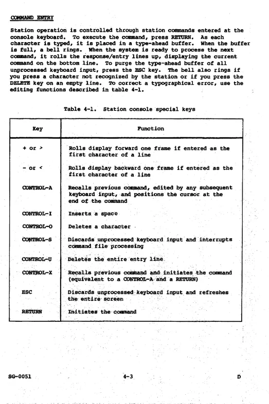
• • •COMMAND ENTRY • • • • • • • • • • STATION COMMAND DESCRIPTIONS
Command formats
.
. . .
.
.
.
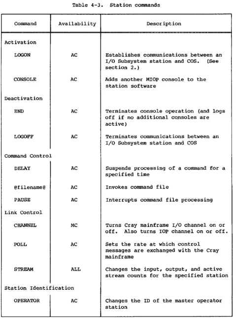
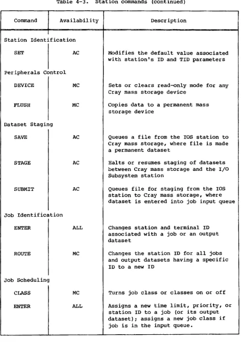
Station command summary • •
· .
.
. . .
.
·
. .
. . .
.
· . . .
.
.
.
.
• •·
.
· . .
.
@filename@ - Command file call • • • • • CHANNEL - Turn channel on or off • • • • CLASS - Turn job classes on or off •• • CLEAR - Clear screen • • • • • • • • • •
• • •
COMMENT
· .
.
.
·
. .
·
.
.
.
Command stream comment • •
· .
.
.
- Alters tape or disk device confiquration Allocate additional station console • • • Display dataset status • • • CONFIGURECONSOLE DATASET
DELAY - Suspend command processinq • • • • •
station command summary (continued)
DEVICE - Change read-only status on mass storage device • • • • • • • • • • • • • • • • • • • • DISK - Display disk statistics • • • • • • • • • • • DROP - Drop job • • • • • • • • • • • • END - End station operation • • • • • • • • • • • • •
ENTER - Change job scheduling parameters • • • • • •
ERROR - Display hardware error information • • • • •
FLUSH - Copy data to backup dataset • • • • • HELP - Display help for commands • • • • • • • • • • JOB - Display job status • • • • • • • • • • • • • • JSTAT - Job status information display • • • • • • • KILL - Kill job • • • • • • • • • • • • • • • • • LEMIT - Limit number of jobs active • • • • • LINK - Link status display • • • • • • • • • • • LOGOFF - Log off station • • • • • • • • • • •
LOGON - Log on station • • • • • • • • • • • • • • • MESSAGE - Enter message into logfile • • • • • • • • MONITOR - Monitor system parameters • • • •
OPERATOR - Change master operator station • • • • PAUSE - Interrupt command file processing • • • • • • POLL - Set control message exchange rate • • • • RECOVER - Recover system • • • • • • • • • • •
REFRESH - Set display refresh rate • • • • • • REPLY - Reply to station request message • • •
RERUN - Rerun job • • • • • • • • • • • • • • • • RESUME - Resume job processing • • • • • • • • • ROUTE - Change station 10 • • • • • • • • • • • •
RSTAT - Display generic resource status • • • • • • • SAVE - Stage permanent dataset • • • • • • • • • • • SCROLL - Use display for command/response scroll area SET - Modify parameters • • • • • • • • • • • • • • • SHUTDOWN - Shut down the system • • • • • • • • SNAP - Print display contents • • • • • • • • STAGE - Halt or resume staging • • • • • • • STATCLASS - Display job class status • • • • • • • • STATION - Display I/O Subsystem station status • • • STATUS - Display system status • • • • • • • •
STMSG - Display station messages • • • • • • • • • • STORAGE - Display mass storage status • • • • • • • • STP - Display System Task Processor statistics
STREAM - Change stream counts • • • • • • • • •
STRSTAT - Display station stream status • • • • • • • SUBMIT - Stage job dataset • • • • • • • • • • •
SUSPEND - Suspend job processing • • • • • • • SWITCH - Manipulate job sense switches • • • • • • • TAPE - Display tape device information • • • • • • • TJOB - Diplay tape job's status. • • • • • •
APPENDIX SECTION
A.
B.
C.
CHARACTER SET. • • • • • •
lOS DUMP PROGRAMS • • • • • •
SYSDUMP • • • •
SYSDUMP parameter list • SYSDUMP code functions • • SYSDUMP messages • • • • DMP. • • • • • • • •
• • • •
• • • •
•
• •
• Load DMP from Peripheral Expander tape • Load DMP from Peripheral Expander disk • DMP messages • • • • •
STATION MESSAGES • • • • • • •
• • • • • • • • • • • • • • • • • • • • • • • • • • • • •
D. DATASET TRANSFERS USING THE PERIPHERAL EXPANDER DEVICES •
E.
F.
DATASET ACQUISITION
DATASET DISPOSITION • •
PERIPHERAL EXPANDER ERROR MESSAGES •
STARTUP FILE CREATION AND MAINTENANCE •
105 FILE EDITOR •
File editor commands • APPEND command BYE command • • • DELETE command INSERT command PRINT command • REPLACE command • TYPE command FILE UTILITIES • • •
• • • • • • • • • • • • • • • • • • • • • • • • • • • • • • • • • • • • • •
Peripheral Expander disk directories • File utility commands
CLEAR utility •
COpy utility DDUMP utility • DEF utility • DELETE utility DLOAD utility • DSTAT utility • EDIT utility FDUMP utility • FLAW utility
• • • • • • • • • • • • • • • • • • • • • • • • • • • • • • • • • • • • • • • • • • • • • • • • • • • • • • • • • • • • • • • • • • • • • • • • • • • • • • • • • • • • • • • • • • • • • • • • • • • • • • • • • • • A-I B-1 B-1 B-2 B-5 B-6 B-7 B-8 B-9 B-9 C-l D-l
• D-l • D-2
G. Ho 10 J. Ko L. M.
File utility commands (continued)
FLOAD utility 0 • 0 0 • • • 0
· .
.
.
.
.
FSTAT utility • 0 0 • • •
.
.
.
..
.
INIT utility 0 • • • • • • 0·
.
.
.
.
.
.
. .
. .
.
PROC utility 0 • 0 •
·
.
.
.
.
.
. .
.
.
RENAME utility
o.
0 • • 0 0·
.
. .
.
.
.
. .
.
File utility error messages
• 0
o •
TAPE MOUNT REQUESTS • • 0 0 • • • • • • • 0 • • • 0 • • • •
ONLINE TAPE DEVICE ERROR MESSAGES 0 • • • •
·
. .
. ·
.
. .
. .
INTERACTIVE STATION COMMANDS· . .4. . . . .
NSC ACTIVITY MESSAGES 0 •
·
. · .
.
• • • •· .
.
.
.
• • • o •JOB CONTROL INFORMATION 0
·
.
.
.
. ·
.
• •FORMATTING THE 80 MBYTE DISK o •
ONLINE DISK DEVICE ERROR MESSAGES • • 0 o • •
00-19 AND 00-29 DISK MESSAGES 0
00-49 DISK MESSAGES • • • • • • • o • • •
· .
·
.
.
.
.
.
o • • o • •
·
.
.
.
.
.
. .
·
. · .
.
·
.
· .
.
. .
.
. .
FIGURES
1-1 A typical Cray Computer System with an I/O Subsystem 0 • •
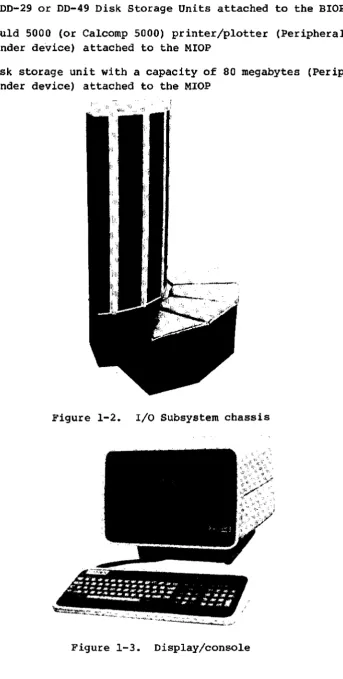
1-2 I/O Subsystem chassis •
· · ·
• 0·
·
• •· ·
•· ·
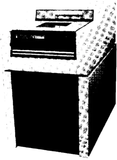
• •1-3 Display/console • • • • 0
·
• • 0·
• • 0·
• 0· ·
0 •·
·
1-4 Peripheral Expander magnetic tape unit • • • • • • 0 • •
1-5 00-29 Disk Storage Unit • • 0
·
0·
• 0 • •·
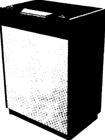
• • • 0 • • 01-6 00-49 Disk Storage Unit • •
·
·
•· ·
• •·
• •·
· ·
•·
•· ·
1-7 Peripheral Expander printer/plotter •
· ·
• •·
•· ·
• •· ·
•1-8 Peripheral Expander disk storage unit 0 0 0 •
·
0·
0·
•·
0 •4-1 Station screen format • • • • • 0
·
• •·
·
•·
• •·
• • •·
•TABLES
3-1 Device commands
.
·
·
• •· ·
• • 0 0 • • 0·
•· ·
0 • •· ·
•4-1 Station console special keys
·
0 • •·
·
• •·
•·
•· ·
•4-2 Command syntax conventions •
·
• •·
• 0 • 0 • •4-3 Station commands
· ·
• 0· ·
0 •· ·
·
0·
I
INTRODUCTION
The Cray Research, Inc., I/O Subsystem is an integral part of all models of the CRAY X-MP and CRAY-l M Series, and models S/1200 through S/4400 of the CRAY-l S Series Computer Systems. This manual describes the
operational features of a Cray Research I/O Subsystem running under the
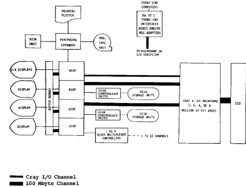
Cray Operating System (COS). Figure 1-1 shows a typical hardware
configuration for a Cray Computer System with a 4-processor I/O Subsystem.
The I/O Subsystem (lOS) handles disk and tape drive activity and provides operator control of COS and its resources. Specifically, the I/O
Subsystem is used to:
• Transmit data between the Cray mainframe and I/O Subsystem
peripherals such as disk units
• Communicate with front-end computers
• Facilitate system maintenance
• Submit jobs through the station (collect and present data to the
Cray mainframe for processing and receive output from the mainframe for distribution to slower peripheral devices)
• Transfer jobs and data as OOS datasets from the I/O Subsystem tape
or disks to Cray mass storage or from Cray mass storage to I/O Subsystem tapes, disks, or printers
• Access interactive COS jobs
Operator maintenance functions (deadstarting the Cray mainframe and dead dumping) are available at the I/O Subsystem when it is linked to the channel providing maintenance control of the Cray mainframe.
HARDWARE CONFIGURATION
An I/O Subsystem consists of a chassis (see figure l-2) housing from two to four I/O Processors (lOPs) and at least one-half million 64-bit words
of Buffer Memory. The four types of lOPs are:
• MIOP
• BIOP
Master I/O Processor (required) Buffer I/O Processor (required)
I
• DIOP
• XIOP
Disk I/O Processor (one or two, optional) Auxiliary I/O Processor (one, optional)
PERIPHERAL
EXPANDER
MIOP
BIOP
DIOP
HOP
. . . . Cray I/O Channel . . . . 100 Mbyte Channel
1 TO 3
BLOCK MUL T! PlEXER CONTROLLERS
FRONT-END COMPUTERS
u~ TO 3 FRONT-ENO INTERFACES
BOXES AltO/OR
NSC ADAPTERS
TO MAINFRAME OR I/O SUBSYSTEM
DISK
STORAGE LIlli TS
- - 1 TO 12 CHANNElS
CRAY )( - MP MAlttFRAME
I, 2. 4. OR B
MiLLION 64-BI1 WOHOS
l1li
100 or 1250 MByte SSD Channels (depending on mainframe type, two VHSP channels can be attached)Figure 1-1. A typical CRAY X-MP Computer System with an I/O Subsystem
In addition to the chassis, the I/O Subsystem consists of the following devices, shown in figures 1-3 tllrough 1-7, respectively.
sso
• Two to four Ampex display/consoles attached to the MIOP and one to
four display/consoles attached to any of the other lOPs
[image:14.595.55.558.139.522.2]I
•
Two DD-29 or DD-49 Disk Storage Units attached to the BIOP or DIOP• A Gould 5000 (or Calcomp 5000) printer/plotter (Peripheral Expander device) attached to the MIOP
I
•
A disk storage unit with a capacity of 80 megabytes (Peripheral Expander device) attached to the MIOPFigure 1-2. I/O Subsystem chassis
[image:15.597.134.477.70.749.2]Figure 1-4. Peripheral Expander magnetic tape unit
.,
.,'"
i~\:!1Ii
[image:16.598.240.356.98.357.2] [image:16.598.196.398.410.685.2]Figure 1-6. DD-49 Disk Storage unit
[image:17.603.192.400.56.372.2] [image:17.603.213.386.466.697.2]I
Figure 1-8. peripheral Expander disk storage unit
The I/O Subsystem can support a maximum of:
•
•
•
•
Three front-end computer interfaces Four display/consoles per processor
12 DCU-4 or DCU-5 Disk Controller unitst
48 DD-29 or DD-49 Disk storage Unitst
If one lOP is dedicated to magnetic tapes (other than Peripheral Expander tapes), the I/O Subsystem can support a maximum of:
• Three Block Multiplexer controllers • 12 Block Multiplexer channels
I/O PROCESSORS
The MIOP (Master I/O Processor) is required. The MIOP communicates with the Cray mainframe and with the other lOPs. The MIOP supports at least two display/consoles, a printer, a magnetic tape unit, and a disk storage unit through the Peripheral Expander. The MIOP can support two
additional display/consoles operating as station consoles, and up to three front-end computer interfaces for Cray mainframe/front-end
[image:18.595.234.355.112.300.2]I
communication: up to three CRI interfaces, or up to three NSC (Network Systems Corporation) interfaces, which can replace any or all of the CRI front-end interfaces.
See section 3 of this manual or the lOS Software Internal Reference
Manual, CRr publication SM-0046, for more information on the NSC adapter.
The BrOp (Buffer rio Processor) is also required. The BIOP connects to a
100 Mbyte channel and transfers data between the Cray mainframe and the I/O Subsystem.
The third and fourth I/O Processors are optional. On a system with four lOPs, both the third and fourth can be DIOPs, for driving additional disk
storage units, or the third can be a OIOP and the fourth an XIOP, for
controlling magnetic tape devices. On a system with three lOPs, the
third can be either a OIOP or an XIOP. A second 100 Mbyte channel can be
configured between the DrOp and the Cray mainframe to improve data streaming rates.
The BIOP and each DIOP include one to four Disk Controller Units, each of which controls up to four Disk Storage Units. The Disk Controller Units may be any combination of DCU-4 and DCU-S controllers. The DCU-4
controller supports DD-29 Disk Storage Units while the DCU-S supports OD-49 Disk Storage Units. Similarly, an XIOP includes one to three Block Multiplexer controllers, each of which includes up to four Block
Multiplexer channels.
The magnetic tape devices attach to the XIOP. The tape units supported
are IBM-compatible 9-track, 200 ips, 1600/6250 bpi devices.
A Cray Computer System can include disk storage units attached directly to the Cray mainframe in addition to those attached to the I/O
Subsystem. Operator commands applying to mass storage devices affect equally disks attached to the Cray mainframe and the I/O Subsystem. The Cray Operating System (COS) tracks the location of each disk storage unit.
The lOPs are connected to each other via an accumulator channel and to Buffer Memory via a 100 Mbyte channel.
SOFTWARE CONFIGURATION
The riO Subsystem software is part of the Cray Operating System (OOS).
As the lOS operator, you are concerned with two parts of the lOS
KERNEL SOFTWARE
The
KePnel
software (the Kernel) controls operations of the I/O Processors. You control the Kernel software viaKePnet aommands
entered at a
KePnel oonsoLe.
Kernel commands and Kernel consoles are so named to distinguish them fromstation oommands
andstation
oon8oles,
which are described next, under Station Software.You can only enter Kernel commands (see section 3) at a Kernel console, and most Kernel commands can be entered only at a Kernel console attached to the MIOP. Any display/console connected to the MIOP is a Kernel
console at deadstart. Following deadstart, all MIOP display/consoles other than one Kernel console can be used as station consoles. Each of the other lOPs has one Kernel console.
You initialize Kernel software at I/O Subsystem deadstart (see section 2). Through Kernel commands, you initiate the station software (a program executing under the control of the Kernel software). Through Kernel commands, you also control the I/O Subsystem's Peripheral Expander devices and perform maintenance functions. You control the use of the concentrator software that allows front-end computers to communicate with
the Cray mainframe and use of the interactive concentrator, which allows communication with an executing COS job. See section 3 for specific
information about Kernel commands.
I/O SUBSYSTEM STATION SOFTWARE
An I/O Subsystem
station
is a software package that provides for operator communication with COS. A station provides a vehicle forentering commands and getting information about Cray system status. (See Appendix I for information about the interactive station.)
Through I/O Subsystem station software, you can submit batch jobs to the
I
Cray mainframe from the Peripheral Expander magnetic tape or disk units and monitor the progress of the jobs submitted.You control station software from a station console. At least one station console must be connected to the MIOP, and the MIOP can have up to two more station consoles attached to it.
You initialize station software at the MIOP Kernel console by entering the Kernel STATION command (see sections 2 and 3). Stations require a unique LOGON ID for communicating with
cos.
You establish communication between COS and the station with the LOGON station command (see sections 2 and 4.).COS designates a station as the
mastep opepatop station
via an installation parameter. This parameter is a default, which can be overridden with the OPERATOR command described in section 4 of this manual.Only one station can serve as the master operator station of a Cray
Computer System at any given time. Whether or not the station logging on is the master operator station depends on its LOGON ID and TID
parameters. (See the LOGON operator command in section 4.)
With the master operator station, you have access to commands that control COS and manipulate all jobs in the system, control all mass
STARTING A CRAY COMPUTER SYSTEM
WITH AN I/O SUBSYSTEM
Startup is the procedure that brings a Cray Computer System with an I/O Subsystem (lOS) to an operational state. The startup procedure consists of three parts: lOS deadstart or restart, Cray mainframe startup, and lOS station initialization. Startup file creation and maintenance is addressed in Appendix F.
The following summaries are quick reference guides to starting the system. The first summary describes startup beginning with lOS deadstart; the second summary describes startup beginning with lOS restart.
CRAY COMPUTER SYSTEM DEADSTART SUMMARY
The following summary is a quick-reference guide to the procedure for 1) deadstarting the lOS, 2) deadstarting the mainframe, and
3} initializing the station. This summary is followed by a summary of the lOS restart process. Details follow the summaries.
1. lOS tape or disk deadstart
a. Set toggle switches on lOS maintenance panel to select unit.
b. Mount tape or disk.
c. Press only the IOP-O MC (MASTER CLEAR on Model A) and DEADSTART buttons on the lOS Power Distribution Unit or the lOS chassis.
Do the next steps at the MIOP KePneL consoLe.
2
d. When the message FILE @MTO: (for tape) or FILE @DKO (for disk) appears on the screen, respond by entering 3 followed by a RETURN
for tape or
dir/fiLename
followed by a RETURN for disk.e. Enter date and time in response to prompts on screen.
2. Mainframe deadstart
b. Wait for CPU <-> MIOP CHANNEL INIT and CPU <-> MIOP
LINKAGE COMPLETE messages.
3. Station initialization
a. At MIOP Kernel console, type STATION.
b. At station console, type LOGON.
c. Do station message/response portion of startup if appropriate.
d. Enter Y followed by a period and press RETURN to check for STARTUP COMPLETE message.
e. Enter station commands such as RECOVER and CONSOLE, depending on site, and enable additional channels with concentrator commands such as NSC and IAIOP, as required.
STARTUP WITH lOS RESTART SUMMARY
The following summary is a quick-reference guide to the procedure for 1)
restarting the lOS, 2) deadstarting the mainframe, and 3) initializing the station. Details on both deadstart and restart follow this summary.
TWo methods are available for the lOS restart portion of startup. Try method A first~ if it does not work, try method B.
1. lOS restart
a. Try method A:
Type CONTROL D at the MIOP Kernel console. If method A works, the following message appears:
SYSDUMP?
To respond to this message, skip method B and continue. If
SYSDUMP? does not appear, try method B.
b. Try method B:
• Press only the IOP-O MC (MASTER CLEAR on Model A) and
DEADSTART buttons on the lOS Power Distribution Unit or the lOS chassis (depending on your site). The following message appears:
SYSDUMP?
If method B is also unsuccessful, an lOS tape or disk deadstart is necessary. Go to the beginning of the first summary (Cray Computer System Deadstart summary).
c. Respond to the SYSDUMP? message by requesting a dump as follows, if one is required; if not, skip to the next procedure, I,d below.
• Enter Y without a RETURN.
• If applicable, select the restart parameter YES to indicate that a restart can be done from the MIOP Kernel console. (See Appendix B in this manual for a description of SYSDUMP.)
d. If a dump is not required, proceed as follows:
• Enter N without a RETURN.
• Enter Y without a RETURN in response to RESTART message.
• Enter the directory name and file name of the Kernel binary previously saved on the Peripheral Expander disk as
dir/fitename.
If a directory name followed by a slash isentered, a list of all files in the requested directory will be displayed.
• Enter date.
• Enter time.
2. Mainframe deadstart
a. At MIOP Kernel console, type START followed by the binary file name and the parameter file parameters.
b. Wait for CPU <-> MIOP CHANNEL INIT and CPU <-> MIOP
LINKAGE COMPLETE messages.
3. Station initialization
a. At MIOP Kernel console, type STATION.
b. At station console, type LOGON.
d. Enter Y followed by a period and press RETURN to check for
STARTUP COMPLETE message.
e. Enter station commands such as RECOVER and CONSOLE, depending on site, and enable additional channels with concentrator commands such as NSC, and IAlOP, as required.
105 DEADSTART DETAILED PROCEDURE
The lOS is deadstarted when the Kernel software is read from tape or disk into the Master I/O Processor (MIOP). To deadstart the lOS, use one of two procedures: tape or disk deadstart.
lOS DEADSTART FROM TAPE
The I/O Subsystem is deadstarted from a previously created file on tape or disk. The following paragraphs describe deadstart from tape.
Setting the toggle switches
To deadstart from tape, you must set the toggle switches on the lOS maintenance panel to 22 (octal) to select the lOS Peripheral Expander
tape unit.
Mounting the tape
The deadstart tape contains the following first five files:
FILE 0
FILE 1
FILE 2
FILE 3
FILE 4
TAPELOAD, the tape deadstart program DISKLOAD, the disk deadstart program DMP, the I/O Processor dump program The Kernel
overlays for the Kernel and the station
Mount the deadstart tape on the lOS Peripheral Expander tape unit (figure 1-4).
Loading the deadstart prqgram
Loading the Kernel
Respond to the prompt FILE @MTO: at the MIOP Kernel console by entering 3 (for file 3) and pressing RETURN, so that TAPELOAD can read the Kernel software into the MIOP.
The Kernel goes through its initialization sequence, reads the overlays from file 4, and displays the following message on the Kernel console of each I/O Processor (lOP):
IOP-n KERNEL, VERSION
x.xx
SNan,aite.
mmVdd/yy hh:mm:ss
n Number designating the I/O Processor where the console is attached
x.xx
Software version numberan
Mainframe serial numbersite
Installation locationmm/dd/yy
Kernel assembly datehh:rrm:S8 Kernel assembly time
The following message can appear on the BIOP or DIOP display only,
indicating that the configured system disk has not responded to attempts to select it. The disk might be disabled at the lOS Power Distribution Unit cabinet or at the disk unit itself (maintenance mode).
DISK NOT READY CH
nn
Entering the date and time
Next, a prompt is issued at the MIOP Kernel console for the current date:
ENTER DATE:
Enter the date in the following format:
rrm/dd/yy
If the year entered does not match the year configured in the system, the following warning message is displayed:
WARNING! Entered year does not match system-configured year.
To change the system-configured year, use the I@YEAR installation
parameter described in the COS Operational Procedures Reference Manual, CRr publication SM-0043.
The following display then appears at the MIOP Kernel console:
ENTER TIME;
Enter the time in the following format:
hh:mm:88
To start the mainframe, go to the mainframe startup description (START command) in this section.
I
lOS DEADSTART FROM PERIPHERAL EXPANDER DISKThe deadstart disk is readied by a CRI systems analyst. The formatting routine for the 80 Mbyte disk, FaOM, is described in Appendix L:
initializing and copy routines are described in Appendix F of this manual.
Setting the toggle switches
To deadstart from disk, you must set the toggle switches on the lOS maintenance panel to 60 (octal) to select the lOS Peripheral Expander disk unit.
Mounting the disk
The disk contains the following files:
DISKLOAD Copied by INIT (Appendix F) from the deadstart tape file 1
DMP Copied by INIT from the deadstart tape file 2
Kernel Copied by COpy (Appendix F) from the deadstart tape file 3 to some directory with a 2-part name of the form:
dir/filename
(directory and filename)Overlays Copied by COpy from the deadstart tape file 4 to some directory with a name of the form:
dir/filename.Ov,
wheredir/filename
is the Kernel filename.Mount the deadstart disk on the lOS peripheral Expander disk unit (figure
Loading the deadstart program
Load the disk deadstart program, DISKLOAD, into the MIOP by pressing only the IOP-O MC (MASTER CLEAR on Model A) and DEADSTART buttons on the Power Distribution Unit or 105 chassis maintenance panel (depending on your site).
Loading the Kernel
Respond to the prompt FILE @DKO: at the MIOP Kernel console by entering either the directory name (di~) to get a menu display of all files in
the requested directory or the Kernel filename (di~/fitenam~ to load the Kernel, and press RETURN. DISKLOAD reads the Kernel software into the MIOP from
dip/fitename.
The Kernel goes through its initialization sequence, reads the overlays, and displays the following message on the Kernel console of each I/O Processor ClOP):
IOP-n KERNEL, VERSION
:t:.xx
SNsn,site.
mm/dd/yy
hh:mm:ss
n
Number designating the I/O Processor where the console is attachedx.xx
Software version numbersn
Mainframe serial numbersite
Installation locationmm/dd/yy
Kernel assembly datehh:mm:ss
Kernel assembly timeThe following message can appear on the BIOP or DIOP display only,
indicating that the configured system disk has not responded to attempts to select it. The disk might be disabled at the 105 Power Distribution Unit cabinet or at the disk unit itself (maintenance mode) •
DISK NOT READY CH
nn
Entering the date and time
Next, a prompt is issued at the MIOP Kernel console for the current date:
ENTER DATE:
Enter the date in the following format:
I
If the year entered does not match the year configured in the system, the
following warning message is displayed:
WARNING! Entered year does not match system-configured year.
Reenter the date. This time the year will be accepted even if it still
disagrees with the system configuration.
To change the system-configured year, use the I@YEAR installation
parameter described in the COS Operational Procedures Reference Manual,
publication SM-0043.
The following display then appears at the MIOP Kernel console:
ENTER TIME:
Enter the time in the following format:
hh:mn:88
To start the mainframe, go to the mainframe startup description (START command) in this section.
STARTUP WITH 105 RESTART DETAILED PROCEDURE
You can restart the I/O Subsystem from files that were restarted from previously saved on an expander disk. Begin restart from disk in one of two ways, depending on whether or not the system is accepting
interrupts. First try method A: type CONTROL D. (If typing CONTROL D
does not work, skip to method B.)
USING CONTROL D (METHOD A)
If the system is accepting interrupts, typing CONTROL D at the MIOP
Kernel console causes the SYSDUMP? message to appear. Use method B,
which follows, if typing CONTROL D does not work. If method A is
successful, skip method B and continue.
USING THE IOP-O Me AND DEADSTART BUTTONS (METHOD B)
First, ensure that no tape is ready on the Peripheral Expander tape drive
I
and that no disk is ready on the Peripheral Expander disk drive. Thenpress only the IOP-O MC (MASTER CLEAR on Model A) and DEADSTART buttons
If both methods are unsuccessful, a tape or Peripheral Expander disk deadstart is necessary. Use the lOS deadstart procedure followed by the mainframe startup and station initialization procedures (see the Cray
computer System deadstart summary or detailed discussions in this section).
RESPONDING TO THE SYSDUMP? MESSAGE
If a system dump is required, continue with this procedure; if a dump is not required, skip this procedure.
Requesting a dump
TO request a system dump:
1. Enter Y without a RETURN.
2. If applicable, select the restart parameter YES to indicate that a restart can be done from the MIOP Kernel console. (See
Appendi~ B in this manual for a description of SYSDUMP.)
Continuing lOS restart without a dump
If a dump is not required, proceed as follows:
1. Enter N without a RETURN.
The following message appears:
RESTART?
2. Enter Y without a RETURN. The next message is: RESTART FILE @DKO:
3. Enter the directory name and file name of the Kernel binary previously saved on the Peripheral Expander disk as
dir/filename.
If a directory name followed by a slash isentered, a list of all files in the requested directory will be displayed.
The following message is displayed on the Kernel console of each I/O Processor (lOP):
IOP-n KERNEL, VERSION X.XX SNsn,
site. mm/dd/yy
hh:mm:s8~.~ Software version number
en
Mainframe serial numbersite
Installation locationmmVdd/yy
Kernel assembly datehh:mm:ss
Kernel assembly timeThe following message can appear on the BlOP or Drop display only,
indicating that the configured system disk has not responded to attempts' to select it. The disk might be disabled at the lOS Power Distribution Unit cabinet or at the disk unit itself (maintenance mode).
DISK NOT READY CB nn
The MIOP Kernel console displays:
ENTER DATE:
Enter the current date in the following format:
rrm/<id/yy
If the year entered does not match the year configured in the system, the following warning message is displayed:
WARNING! Entered year does not match system-configured year.
Reenter the date. This time the year will be accepted even if it still disagrees with the system configuration.
To change the system-configured year, use the I@YEAR installation
parameter described in the COS Operational Procedures Reference Manual, publication SM-0043.
The console then displays:
ENTER TIME:
Enter the time in the following format:
hh:mm:s8
To start the mainframe, see the START command described next under
I
I
I
I
MAINFRAME DEADSTART
TO deadstart the Cray mainframe after deadstarting or restarting the I/O Subsystem, enter the START Rernel command with its parameters for the two required files at the MIOP Rernel console. The two required files are:
• Binary file containing the operating system code
• Parameter file
The CRI systems analyst creates the parameter file, using procedures
defined in Appendix F of this manual.
The START command tells the lOS Rernel program where the files required for deadstart are stored and establishes the link between the lOS and the mainframe.
As reflected by the START command parameters (see the following
definitions), each of the two mainframe startup files can be stored on either magnetic tape or expander disk.
The command syntax conventions used in the START command format below are summarized in table 4-2.
Format:
{@MTunit:num
} {@MTunit:nwn
START
(@DRunit:][dip/lfile
l@DKunit:](dip/]file
Parameters:
@MT
unit
num
dil'
@DR
file
@TT
@T'!'
Peripheral Expander tape device
Unit number (0-9)
Physical file number on tape (0-9999)
Directory name on disk; maximum of 15 alphanumeric
characters
Peripheral Expander disk device
File name on disk; maximum of 15 alphanumeric characters
I
I
ED Option to route the parameter file through the editor before going to the mainframe. This option cannot be specified with the @TT parameter.
If a device is not specified, the expander disk unit 0 is used. If a directory name is not specified, the default directory (see the DEF
utility in Appendix F) is used.
Examples:
START @MTO:5 @MTO:6
In this example, the COS binary file is file number 5 and the parameter file is file number 6. Both are on tape unit
o.
START @DKO:ABC/COS @DKO:XYZ/DEADSTART
In this example, the OOS binary file is cos in directory ABC, and the parameter file is DEADSTART in directory XYZ. Both files are on disk unit
o.
START ABC/COS DEADSTART
In this example, the COS binary file is COS in directory ABC, and the parameter file is DEADSTART in the default dir@ctory (see the DEF utility in Appendix F). Both files are on the default device, disk unit
o.
A parameter file that was saved previously can be modified by the EDIT utility (described in Appendix F) as follows:
START COS DEADSTART,ED
After you enter the START command, a CPU <-> MIOP CHANNEL INIT
message appears on the MIOP display/console. Then wait for the CPU
<-> MIOP LINKAGE COMPLETE message to appear. If mainframe deadstart is not successful, error messages are displayed instead of the CPU
STATION INITIALIZATION
The next phase in bringing a Cray Computer System to an operational state is to bring up the station software.
1. Initialize the station software by entering the STATION Kernel command at an MIOP Kernel console:
STATION [ nwn]
(The STATION Kernel command is explained in detail in section 3
of this manual.)
The following information appears at the console specified by the
num
parameter of the STATION command (nummight be a default value):CRAY STATION, VERSION
x. xx
2. Establish communication between the station and the Cray mainframe by entering the LOGON station command at the
initialized station console:
LOGON [ , id] [,
tid]
(The LOGON station command is explained in detail in section 4 of th i s manual.)
3. At the master operator station (described in section 1), respond to all messages that occur during startup. The display/console responds to LOGON by beeping and displaying an M (as shown in figure 4-1) at the top of the screen to indicate that a
response-required message is waiting_ Display the station messages by entering the STMSG station command (section 4):
STMSG
The messages that appear at this time have the following general format and content:
msgnum
time
PFobtem-speoifio prompt Fequiring
analyst interaotion
OF ENTER GO OFTo ignore the messages and continue with startup, use the REPLY response with GO, SKIP, or CONTINUE, as indicated by the STMSG display. An example of this type of response is:
REPLY msgnwn GO
If any other response is required, see the CRI systems analyst. Because all messages potentially require interaction with the CRI systems
analyst, they are documented for the analyst in the COS operational Procedures Reference Manual, CRI pUblication SM-0043.
4. Check for the STARTUP COMPLETE message by entering the following:
Y.
RETURN
5. Depending on the site,t you typically enter the following station commands, described in section 4, to complete the procedures that bring the system to an operational state:
STATUS RECOVER LIMIT
CHANNEL n ON CONSOLE 1
As required, also enter the NSC and IAIOP concentrator commands (described in section 3) to enable additional channels.
KERNEL COMMANDS
3
The Kernel program in the Master I/O Processor (MIOP) allows you to
control the I/O Subsystem (lOS) via the commands you enter at a dedicated console (the Kernel console). These commands are called Kernel
commands. Kernel commands are not recognized by the station software.
For an overview of the Kernel software, see section 1.
KERNEL CONSOLE
The display/console at which Kernel commands are entered is called the
Kernel console.
A Kernel command can be entered only at a Kernelconsole, and most Kernel commands can be entered only at an MIOP Kernel console.
All display/consoles are Kernel consoles when the I/O Subsystem is deadstarted; one console is dedicated to the MIOP Kernel by default.
This console cannot be dedicated to station software; attempting to
assign this console to station software results in the following message:
CRT NOT AVAILABLE FOR ASSIGNMENT
See the CONSOLE command in section 4 for more information about console assignment to a station.
Since all MIOP consoles are initially Kernel consoles, any MIOP console can be used to enter Kernel commands when not dedicated to the station.
All Kernel operator messages, including peripheral Expander tape mount requests and device error messages, are directed to this console.
The following special keys on the Kernel console are recognized by the Kernel command processor.
RETURN Initiates the command
RUBOUT or DEL Backspaces and erases one character on the entry line CONTROL-A Repeats the last input line
I
I
CONTROL-H Backspaces one character but does not erase
CONTROL-U Deletes the entire entry line
CONTROL-X Repeats the last input line and initiates the command
Right arrow Moves cursor right One character (CONTROL-L)
Left arrow Moves cursor left one character (CONTROL-H)
TYPES OF KERNEL COMMANDS
A Kernel command consists of a unique command verb that can be accompanied by parameters. Table 4-2 describes command syntax
conventions. A Kernel command is executed when you press the RETURN key
on the Kernel console.
Some commands are operator responses requested by the Kernel.
The following types of Kernel commands are described in this section.
• Initialization • Concentrator • Device
• Peripheral Expander tape and disk mount responses • Miscellaneous maintenance
The following types of Kernel commands are described in other sections of this publication:
• START command to deadstart the Cray mainframe (section 2)
• I/O Subsystem file editor commands (Appendix F) • File utility commands (Appendix F)
INITIALIZATION COMMANDS
Initialization commands allow you to initialize software and prepare the Cray Computer System for job processing.
CRAY command
Typically, the link between the lOS and the mainframe is established via
the START command described in section 2. However, you can enter the
CRAY command at the Kernel console when you have restarted the lOS but not the mainframe.
Format:
When the link is successfully established, the following messages appear on the Kernel console:
CPU <-> MIOP CHANNEL INIT CPU <-> MIOP LINKAGE COMPLETE
If an error is encountered, the message is issued:
CPU NOT RESPONDING - RETRY?
or
LOW SPEED CHANNEL DATA ERROR
DATA EXPECTED:
DATA RECEIVED: CONTINUE?
:x::x::x::r:=r:
yyyyyy
Enter Y (yes) to attempt initialization again; enter N (no) to
terminate. Upon termination, the following message is issued:
CPU <-> MIOP LINKAGE FAILED
STATION conunand
To initialize the I/O Subsystem station software, enter the STATION Kernel command (also described in section 2).
Format:
STATION [num]
num Number (0-3) of the console attached to the MIOP. If not
I
at any console other than the Kernel console is the console at which the command is entered. The default at the Kernel console depends on the I/O Subsystem configuration.
Consult a Cray Research systems analyst for the I/O Subsystem configuration. The Kernel console cannot be assigned as an lOS station software console.
NOTE
The STATION Kernel command described here and the STATION command described in section 4 are not the same 1 they perform different functions.
To establish communication between COS and a station, see the LOGON station command described in sections 2 and 4.
MASTER command
The I/O Subsystem must know the 10 of the master disk device, which contains the startup files and is normally set up at installation time.
The master disk device ID is the channel number and the I/O Processor to which the master disk device is connected, and is also the device type. The master device ID is set to channel 20, lOP-I, OD29 by default during IDS deadstart. The MASTER command is used to verify or change the master device ID.
TO verify the master device 10, enter the MASTER command without parameters.
Format:
I
The console displays the channel, lOP number, and device type, respectively, as fOllows:I
MASTER 20-1 DD29I
Format:
MASTER
chan-iop [type]
chan
iop
type
New channel number
New lOP number, as follows:
1 BlOP
2 lOP-2 (if it is a OIOP)
3 lOP-3 (if it is a DIOP)
Optional device type. If
type
is not specified, the master device type remains unchanged. Options are:0019 00-19 Disk
0029 00-29 Disk
0049 00-49 Disk
The new channel number, lOP number, amd device type are displayed.
CONFlG command
The CONFIG Kernel command displays the status of configured peripheral devices. Use this command at any time to determine the availability of a configured device.
Format:
CONFIG
Iiop]
The CONFlG command displays the following lOP configuration information.
• Identification of the device attached to each channel
• Operational status of each device
• Composition of Local (MIOP) Memory: Number of Disk Activity Links COALs) Number of 4000a-parcel I/O buffers
Number of software stacks in Buffer Memory Number of parcels allocated for overlays
• The Kernel operator console channel number for the I/O Processor (displayed with an asterisk preceding the number)
iop
Number of the lOP (0-3) to be displayed. The default isthe number of the lOP attached to the console at which the command is entered.
NOTE
The CONFIG Kernel command described here and the OONFIG
command described in section 4 are not the same; they
perform different functions.
HELP command
The HELP command displays helpful information on all Kernel commands.
Format:
HELP [cmd]
Name of command for which help is desired. If null, all Kernel commands are listed. If not unique, all possible choices are listed.
TTY command
The TTY command allows you to assign an MIOP console other than the kernel console for use as a special-purpose terminal. This
special-purpose terminal permits communication with the Cray mainframe in
an operating system environment that is unique to certain sites. The TTY
command is used only in selected Cray sites that use the special-purpose
terminal. The TTY command is not used with the Cray Operating System
(COS).
NOTE
The TTY command should not be invoked when the Cray
Format:
TTY dev [furze]
dev
tunc
Octal device address of terminal~ for example, 40.
Specifies start of terminal session. Determines how the special purpose terminal and the mainframe interpret, echo, and process all characters. Omitting this parameter starts the terminal session in cooked-input mode. (A discusssion of cooked- and raw-input modes follows the parameter descriptions.)
END Stop terminal session
TABS Change tab stops, up to 10 decimal integers
(default is 1, 9, 17, 25, 33, 41, 49, 57, 65, and
73)
During input mode, the following conditions apply.
• Your use of the carriage return or newline on the special-purpose terminal sends a line to the mainframe
• Tab characters sent from the mainframe are interpreted at the terminal
Use the following characters to edit your text. These characters are not sent to the mainframe.
Character
CONTROL-a CONTROL-e CONTROL-u CONTROL-x DEL
<-->
Description
Recall last line Toggle insert
mode
Erase current line
Recall and execute last line
Delete character to left of cursor (rubout) Cursor left (left arrow)
Cursor right (right arrow)
Non-printable or control characters are interpreted depending on the terminal being used.
CONCENTRATOR COMMANDS
communicates with an NSC (Network Systems Corporation) adapter: and a
third supports interactive communication
withCOS through the
display/console.
Communication with CRI front-end interface
The I/O Subsystem concentrator communicates with a CRI front-end
CONC command - The CONC command initiates the concentrator. A concentrator can be implicitly initiated during startup or can be initiated by the station CHANNEL ON command. If the concentrator is terminated (see the ENDCONC command following), the CONC command must be used to re-initiate it.
Format:
oh Number pair (0-2), which maps to a channel pair connecting the I/O Subsystem to the front-end computer system. The default is
o.
Consult a Cray Research system analyst for the I/O Subsystem configuration.If successful, initialization is recognized with the following message:
CONCENTRATOR NUMBER eh INITIALIZED
ENDCONC command - To terminate the concentrator, which is implicitly initiated by the START command or explicitly via the CONC command, enter the ENDCONC command.
Format:
ENDCONC [eh]
eh Number assigned in CONC statement when CONC was used to initiate the concentrator
When all resources are released, the following message appears:
CONCENTRATOR NUMBER oh TERMINATED
Communication with an NSC Al30 adapter