362
ANALYSIS ON EFFECT OF EXCITATION FREQUENCY ON
NONLINEAR CHARACTERISTICS OF A GEAR PAIR
SYSTEM BASED ON NUMERICAL SIMULATION
JUNGANG WANG, YONG WANG, ZHIPU HUO
School of Mechanical Engineering, Shandong University, Jinan 250061,Shandong, China
ABSTRACT
A nonlinear dynamic model of the geared rotor system, with consideration of the bearing clearances and gear backlashes, is established. A numerical algorithm based on Runge–Kutta-Butcher method is used to study the nonlinear behaviors of the system accounting for the effects of different excitation frequency. A detailed parametric research is conducted to analyze the influences of the excitation frequency on the nonlinear characteristics of the system. The final goal of the work is to study bifurcation and chaotic behavior of a gear pair model that includes nonlinearities due to bearing and teeth backlash. The analyses are performed in a parametric manner using non-dimensional excitation as bifurcation parameters. The results show that the different excitation frequency can significantly influence the nonlinear dynamic responses.
Keywords:Nonlinear Response, Excitation Frequency, Bifurcation Phenomena
1. INTRODUCTION
Geared rotor systems can be found in a wide range of automotive, aerospace, marine, wind turbine and industrial applications. The dynamic response of a geared rotor system, in generally, depends on the time-varying stiffness, static transmission error, gear backlash, the damping coefficient ratio and excitation loads. These parameters have direct effects on the dynamic response and performance of the system. The nonlinear dynamic behaviors of the system are investigated and the several studies on the effect of systematic parameter on the dynamic response are summarized as follows.
A considerable amount of studies on the dynamic model for the dynamic analysis of geared rotor system are reported by many researchers[1,2,3,4]. Raghothama and Narayanan [5] carried out the incremental harmonic balance method to investigate the periodic motions of a non-linear geared rotor-bearing system. It was conducted that the system exhibited a period doubling route and a quasi-periodic route to chaos in different regions of excitation frequency. Vedmar and Anersson[6] presented a method to calculate dynamic gear tooth force and bearing forces where the bearing model was under elastic bearings assumption. Alhyyab and Kahraman[7] investigated steady state period-one motions of a nonlinear geared rotor-bearing
system by using a multi-term harmonic balance method in conjunction with discrete Fourier transforms. Rui and Chen[8] analyzed the dynamic response of gear model under primary resonance and 1/2 sub-harmonious resonance by means of averaging method. Vaishya and Singh[9] used a sliding friction method to simulate the nonlinear dynamics of a gear system in order to obtain insights into the relative effects of sliding friction and mesh damping, respectively. Liu and Robert[10] examined a nonlinear, parametrically excited dynamics of idler gear sets. The periodic steady state solutions were obtained using analytical and numerical approaches. Li et al[11] applied the theory of multiple scales method to research the vibration behaviors of gear system.
363 fast Fourier transform spectra and bifurcation diagrams in detail.
2. MODELING AND EQUATION OF
MOTION
Td
Fd fd(xd)
kd cd e(t)
fr(xr) kr
cr
Tp
θp xp fp(xp)
kp cp θd
md
,
Id,Rdmp
,
Ip,Rp Fpxd
Figure 1: Nonlinear Model Of A Gear Pair System
The nonlinear model of a geared rotor system considered in this study is shown in Figure1. In this model it is assumed that the system is symmetric about the plane of the gears and the axial motion is negligible. Bearings and shafts that support the gears are represented by equivalent damping, linear stiffness and clearance elements as shown in Figure1. The damping elements are characterized by linear viscous damping coefficients cd and cp
The bearing clearance elements are defined by
force-displacement function fd(xd) and fp(xp) .
The support stiffness elements are represented by
corresponding scaling constants kd and kp
External radial preloads are applied to both the rolling element bearings. Therefore, the essential vibration of the system can be described by four degrees of freedom system, with coordinates
T p x d x p d
X =[θ θ ] (1)
By using Newton's second law, the corresponding equations of vibration are obtained in the general form
= − + = + + = + + − = − = + p F r x r x d r h p x p x p h p x p m d F r x r x d r h d x d x d h d x d m d F r x r x d r h d x d x d h d x d m p p t p T r x r x d r h p R p p I d d t d T r x r x d r h d R d d I ) , , ( ) , ( ) , , ( ) , ( ) , , ( ) , ( ) , , ( ) , , ( ) , , ( ) , , ( θ θ θ θ θ θ θ θ θ θ θ (2 )
This model takes into account the static transmission, e(t) representing geometrical errors
of the gear teeth profile and spacing. In addition, the quantity ) ( ) ( ) ( )
(t Rd d Rp p xd t xp t e t
r
x = θ − θ + − − (3
)
is known as the dynamic transmission error.
The damping mechanism in both the gear mesh and the bearings are assumed to be linear, so that the corresponding forces may be expressed in the simpler form = + = + = ) , ( ) ( ) , ( ) , ( ) , , ( p d n n x n f n x n c n x n x n h r x d r h r x r c r x r x d r h θ θ (4)
In these equations, xd and xp are the transverse displacements of the gears; θd and θp are the
wheel angular positions; md and mp are the gear masses; Id and Ipare the mass moments of inertia of the gears; Rd and Rp are the base circle radii of
the gears. kr is the gear mesh stiffness; cr
represents the linear viscous damping of the gear
mesh; the quantity Td(t,θd,θd) represents the moment input to the driving gear, while,
) , ,
( p p
p t
T θ θ is the resistant moment developed on
the driven gear during the motion. Fd and Fp refer
to the bearing pretension radial forces applied on the gear centers.
Furthermore, taking into account the gear backlash, the gear meshing restoring force component is expressed in the form
r r r r d
r x f x k
h(θ , )= ( ) (5)
where kr represents the gear mesh stiffness, while − ≤ + ≤ ≥ − = l r x l r x l r x l r x l r x r x r
f ( ) 0 (6)
and 2l represents the total gear backlash.
Likewise, the restoring forces in the bearings is expressed in the classical linear form
n n n
n x k x
f ( ) = (7)
364 + = − = d p p d p d e p p d d R I R I R I I m R R x 2 2 θ θ (8)
The original set of equations of motion (2) can be obtained in the following form
= − − + + − − + + = − − + − + − − + − + − = − − + + + − − + + + Ro F t e p x d x R x r f r k t e p x d x R x r c R x e m p F t e p x d x R x r f r k p x p f p k t e p x d x R x r c p x p c p x p m d F t e p x d x R x r f r k d x d f d k t e p x d x R x r c d x d c d x d m )) ( ( )) ( ( )) ( ( ) ( )) ( ( )) ( ( ) ( )) ( ( (9)
Dimensionless forms of the above equations are obtained by letting
= = = = = = = = = = = = = = = = d d Ro n e o o n e Ro Ro p e n p p p n d d d i n d r d e n i i n i i i e r n r r i i R T F b m F F b m F F m m k b m F F b m F F b e F m c m m k t t m k m k b t x t x b t x t x ), ( ) ( , ) ( , ) ( ) ( , ) 2 ( , , d), p, (i , ) ( ) ( , ) ( ) ( 2 2 23 2 2 13 13 ω ω ω ω ω ζ ω ω ω ω ω ω (10)
The dimensionless governing equations of motion (9) are yielded in the normalized form
) (t F Kf U C U
M+ + = (11)
with b b x r p d i b b x b b b b x b b x b b x x f i i i i i i i i i i i i i − < = ≤ ≤ − > + −
= 0 , ,
)
( (12)
) sin( 0 0 ) sin( 0 0 ) ( 2 o o o i i i i Ro p d t F t F F F F t
F ω ψ ω ψ
ω + + + − −
= (13)
= − = − = − = ) ( ) ( ) ( 1 0 0 0 0 0 0 0 0 2 1 0 1 0 1 0 0 0 1 23 22 13 11 33 23 22 13 11 r r p p d d x f x f x f f k k k k K C M ζ ζ ζ ζ ζ (14)
3. NUMERICAL SOLUTIONS
The nonlinear dynamic equations presented in equation (11) for the geared rotor system are solved by using the fifth order Runge–Kutta-Butcher method. The algorithm is written as
h k k k k k y
yi i (7 32 12 32 7 )
90 1 6 5 4 3 1
1= + + + + +
+ (15)
where + − + + − + = + + + = + − + = + + + = + + = = ) 7 8 7 12 7 12 7 2 7 3 , ( ) 16 9 16 3 , 4 3 ( ) 2 1 , 2 1 ( ) 8 1 8 1 , 4 1 ( ) 4 1 , 4 1 ( ) , ( 5 4 3 2 1 6 4 1 5 3 2 4 2 1 3 1 2 1 h k h k h k h k h k y h t f k h k h k y h t f k h k h k y h t f k h k h k y h t f k h k y h t f k y t f k i i i i i i i i i i i i (16)
365
4. RESULTS AND DISCUSSIONS
1.06 1.08 1.1 1.12 1.14
-0.03 -0.02 -0.01 0 0.01 0.02 0.03
Dimensionless displacement
D
im
en
sio
n
le
ss
v
elo
city
(a)
0 0.5 1 1.5 2 2.5
-1 -0.5 0 0.5 1 1.5
Dimensionless displacement
D
im
en
sio
n
le
ss
v
elo
city
(b)
0.75 0.8 0.85 0.9 0.95 1 0
0.005 0.01 0.015 0.02 0.025 0.03 0.035 0.04
Dimensionless frequency
D
im
en
sio
n
le
ss
a
m
p
litu
d
e
(c)
Figure 2: Simulation Obtained For k11=0.25, k22 =0.25 With ωi =0.8675,
(A) Phase Diagram; (B) Poincaré Map; (C) Power Spectrum.
To test the existence of the essential dynamics of the geared rotor system and provide valuable insights into its nonlinear dynamic behavior, the phase diagrams, the Poincaré maps and the power spectra of the system are illustrated in Figures.2-5.
Figure 2 shows simulation obtained for k11=0.25,
22
k =0.25 with ωi =0.8675. From Figure2, we can
see that the spectrum graph includes mesh frequency 0.8675; the phase plane is a circle; the Poincaré map is a point. It shows that the vibration
of the system is a simple harmonic motion.
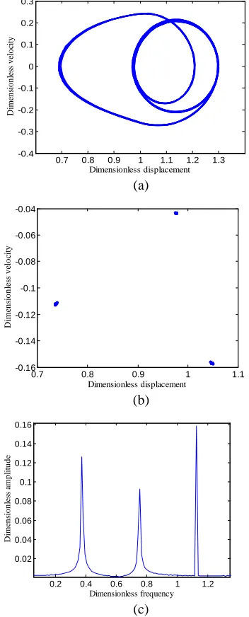
Figure 3 presents simulation obtained for
11
k =0.25, k22=0.25 with ωi=1.1256. From Figure 3, we can observe that the spectrum graph includes
mesh frequency 1.1256 and n1.1256/3 (n=0, ±1,
±2…) frequencies; the phase plane is a 3-looped circle; the Poincaré map includes three points. It is concluded that the vibration of the system is 1/3 sub-harmonic motion.
0.7 0.8 0.9 1 1.1 1.2 1.3
-0.4 -0.3 -0.2 -0.1 0 0.1 0.2 0.3
Dimensionless displacement
D
im
en
sio
n
le
ss
v
elo
city
(a)
0.7 0.8 0.9 1 1.1
-0.16 -0.14 -0.12 -0.1 -0.08 -0.06 -0.04
Dimensionless displacement
D
im
en
sio
n
le
ss
v
elo
city
(b)
0.2 0.4 0.6 0.8 1 1.2
0.02 0.04 0.06 0.08 0.1 0.12 0.14 0.16
Dimensionless frequency
D
im
en
sio
n
le
ss
a
m
p
litu
d
e
[image:4.612.93.516.71.625.2](c)
Figure 3: Simulation Obtained For k11=0.25,
22
k =0.25 With ωi=1.1256. (A) Phase Diagram; (B) Poincaré Map; (C) Power Spectrum.
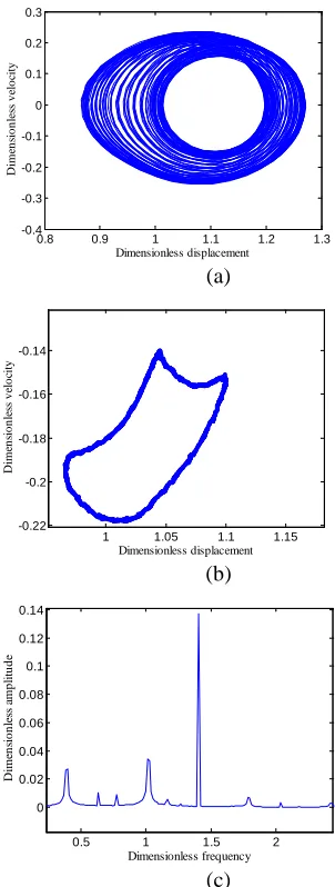
Figure4 depicts simulation obtained for k11=0.25,
[image:4.612.323.499.215.651.2]366 found that the spectrum graph consists of two fundamental frequencies ω1 and ω2 at a ratio ω1
/ω2 and there are peaks at the combination
frequencies mω1+nω2 (m, n=0, ±1, ±2…); the
phase plane is a shaped belt; the Poincaré map is a deformed closed orbit. It is implied that the vibration of the system is quasi-periodic motion.
0.8 0.9 1 1.1 1.2 1.3
-0.4 -0.3 -0.2 -0.1 0 0.1 0.2 0.3
Dimensionless displacement
D
im
en
sio
n
le
ss
v
elo
city
(a)
1 1.05 1.1 1.15
-0.22 -0.2 -0.18 -0.16 -0.14
Dimensionless displacement
D
im
en
sio
n
le
ss
v
elo
city
(b)
0.5 1 1.5 2
0 0.02 0.04 0.06 0.08 0.1 0.12 0.14
Dimensionless frequency
D
im
en
sio
n
le
ss
a
m
p
litu
d
e
[image:5.612.96.521.62.563.2](c)
Figure 4: Simulation Obtained For k11=0.25,
22
k =0.25 With ωi=1.4060. (A) Phase Diagram; (B) Poincaré Map; (C) Power Spectrum.
Figure 5 denotes simulation obtained for
11
k =0.25, k22=0.25 with ωi=1.4060. From Figure 5, we can see that a characteristic broad spectrum is obtained; the phase plane is a chaotic strange attractor; the Poincaré map includes many points. It is concluded that the vibration of the system is chaotic motion.
0.8 1 1.2 1.4 1.6
-0.4 -0.3 -0.2 -0.1 0 0.1 0.2 0.3 0.4
Dimensionless displacement
D
im
en
sio
n
le
ss
v
elo
city
(a)
0.8 0.9 1 1.1 1.2 1.3
-0.4 -0.3 -0.2 -0.1 0 0.1 0.2 0.3
Dimensionless displacement
D
im
en
sio
n
le
ss
v
elo
city
(b)
0.5 1 1.5 2
0 0.02 0.04 0.06 0.08 0.1 0.12
Dimensionless frequency
D
im
en
sio
n
le
ss
a
m
p
litu
d
e
[image:5.612.301.518.67.535.2](c)
Figure 5: Simulation Obtained For k11=0.25,
22
k =0.25 With ωi=1.4150. (A) Phase Diagram; (B) Poincaré Map; (C) Power Spectrum.
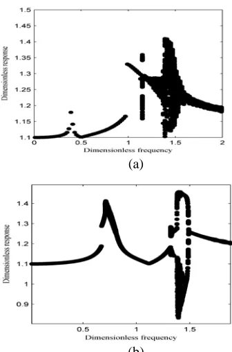
Figure 6(a) presents bifurcation diagram for the meshing gears in the line of action direction for
11
k =0.25, k22 =0.25. With the changes of
excitation frequency ωi the vibration of the system also changes. It can be observed that geared rotor system exhibits periodic motion at almost of the dimensionless coefficient of ωi, i.e. ωi < 1.1256.
Furthermore, whenωi is 1.0, the mesh frequency
closes to the natural frequency of the system and the jumping phenomenon occurs. However, at a
higher dimensionless ration of ωi = 1.4060, the
[image:5.612.101.252.182.581.2]367 characterized by chaotic motion in the intervals with ωi = 1.2335-1.4057 and ωi > 1.4062. The results show that the system vibrations change from periodic motion to chaotic motions through 3-period bifurcation, and changes from chaotic motions to periodic motion by inverse quasi-period bifurcation.
(a)
[image:6.612.101.269.195.449.2](b)
Figure 6: Bifurcation Diagrams Of Meshing Gears In The Contact Line Direction Using Dimensionless
Frequency, ωi As Bifurcation Parameter With
i
F =0.0532, ξ33 =0.0516: (A) k11=0.25, k22=0.25; (B) k11=1.75, k22=1.75.
Figure 6(b) shows bifurcation diagram for the meshing gears in the line of action direction for
11
k =1.75, k22=1.75. Comparison of the bifurcation diagram with those presented in Figure 6(a), it can be seen that the system shows 1T-periodic motion at low values of the dimensionless frequency, i.e.
i
ω ≤ 1.3253. However, as ωi is increased from
1.3253 to 1.3673, the 1T-periodic motion is
replaced by sub-synchronous 2T-periodic motion.
Chaotic behavior appears as the dimensionless frequency is further increased from ωi =1.3673 to
i
ω =1.4923. The system also exhibits periodic
motion at high values of the dimensionless frequency, i.e. ωi > 1.4923. Moreover, there are jumping phenomena at the dimensionless frequency
of ωi =0.6051 and ωi =1.3675. Thus, it can be
inferred that the dynamic responses change from periodic motions to chaotic motions by double-period bifurcation and from chaotic motions to periodic motions by inverse double-period bifurcation.
5. CONCLUSIONS
In the present paper, the nonlinear model is proposed to study the dynamic behaviors of the gear pair based on the numerical method of the RKB. The results show that the different excitation frequency can significantly influence the nonlinear dynamic response. There are three kinds of forced stead responses, i.e. simple harmonic, sub-harmonic and chaotic responses. The system responses transform from periodic motions to chaotic motion through double-period bifurcation and from chaotic motions to periodic motions by inverse double-period bifurcation.
ACKNOWLEDGEMENTS
This work was supported by the Chinese National Science Foundation (No.50775130), Shandong Provincial Natural Science Foundation,
China (No.ZR2010EM012), Independent
Innovation Foundation of Shandong University (IIFSDU2012TS044) and the Graduate Independent Innovation Foundation of Shandong University, GIIFSDU (No.31360070613215).
REFERENCES:
[1] O. Nevzat, D. Houser, “Dynamic analysis of high speed gears by using loaded static transmission error”, Journal of Sound and Vibration, Vol. 125, No. 1, 1988, pp. 71-83.
[2] T. Rook, R. Singh, “Dynamic analysis of a reverse-idler gear pair with concurrent clearances”, Journal of Sound and Vibration, Vol. 182, No. 2, 1995, pp. 303-322.
[3] Q. Zhang, L. Tang, “Nonlinear dynamic fault model of gear transmission system with gear tooth crack”, Journal of Vibration Engineering, Vol. 24, No. 3, 2011, pp. 294-298.
[4] R. Parker, S. Vijayakar, “Non-linear dynamic response of a spur gear pair: modeling and
experimental comparisons”, Journal of Sound
and Vibration, Vol. 237, No. 4, 2000, pp. 435-455.
368
Journal of Sound and Vibration, Vol. 226, No. 3, 1999, pp. 469-492.
[6] L. Vedmar, A. Anersson, “A method to determine dynamic loads on spur gear teeth and on bearings”, Journal of Sound and Vibration, Vol. 267, No. 5, 2003, pp. 1065-1084.
[7] A. Alhyyab, A. Kahraman, “Non-linear dynamic analysis of a mesh gear train using multi-term harmonic balance method: Sub-harmonic motions”, Journal of Sound and Vibration, Vol. 279, No. 1, 2005, pp. 417-451.
[8] M. Rui, Y. Chen, “Nonlinear dynamic research on gear system with cracked failure”, Journal of Mechanical Engineering, Vol. 47, No. 21, 2011, pp. 84-90.
[9] M. Vaishya, R. Singh, “Sliding friction-induced nonlinearity and parametric effects in gear
dynamics”, Journal of Sound and Vibration,
Vol. 248, No. 4, 2001, pp. 671-694.
[10] G. Liu, G. Robert, “Nonlinear dynamics of idler gear systems”, Nonlinear Dynamics, Vol. 53, No. 4, 2008, pp. 345-367.
[11] G. Li, G. Yu, “Method of multiple scales in solving nonlinear dynamic differential
equations of gear systems”, Journal of Jilin