ANALYSIS ON EFFECT OF BEARING TYPES ON
CONTINUOUS GIRDER BRIDGES UNDER SHIP COLLISION
1GUOQIANG XIE, 2WEI HU
1Henan Polytechnic University, Henan 454000, Jiaozuo, China, [email protected]
2Beijing municipal bridge maintenance management group Co.Ltd, 100097, Beijing, China
ABSTRACT
After analyzing the existing simplified methods of ship-bridge collision and comparing their pros and cons, a relatively safe simplified analysis process is put forward. The time-history curve of the ship collision force obtained from the ship-rigid wall collision simulation using the software LS-DYNA is put into the whole bridge dynamic model in SAP2000 and then dynamic response analysis of the whole ship has been carried on. Respect to the bridge with ordinary fixed bearings and seismic isolation bearings, the influence of the bearing type on the key structure of the bridge are analyzed. Then the features and rules of the continuous bridges dynamic responses with different bearings under different ship-bridge collision angle and velocity are obtained.
Keywords: Continuous Bridges, Ship Collision, Bearings, Numerical Stimulation, Collision Angle,
Bearing Type
1. INTRODUCTION
The bridge is an important transport hub of the traffic system. In recent years, with the rapid development of China’s economy, more and more long-span bridges over rivers and straits have been built, and capacity, quantity and speed of the ships are constantly growing, which increases the potential risk of bridge collision. The ship-bridge collisions happen frequently both at home and abroad.
The process of ship-bridge collision, which belongs to the area of impact dynamics, is exceptionally complicated. The dynamic load of the collision interface is determined by the transmission process of the coupled waves between the collision objects. The transmission of the wave varies due to the difference of the structures and material of the ships, the bridge piers and the safeguard facilities. Under ship-bridge collision, many factors, such as the weather, wind, waves and water current, will influence the collision force and the responses of the bridge structure. The features of the ships including the type, size, internal structure and speed and angle of the ship- bridge collision, size and material of its components are also important factors to be considered.
The bearings are connected the girder and the pier. Theory and experiment show that the bearing
type has a great influence on the bridge dynamic responses. In the study of bridge seismic resistance, the flexure supporting structure and power – dissipation structure can reduce the bridge dynamic response under earthquake by lengthening the structural period and consuming energy. Though massive research on the technology of seismic absorption and isolation has been done by domestic and foreign scholars[1-3], influence of the bearing, as the joint of the upper and lower structures, on the collision force under the ship-bridge collision has not been studied. This article analyzes and studies the continuous bridges with ordinary fixed bearings and seismic isolation bearings respectively under the ship-bridge collision.
2. SIMPLIFIED ANALYSIS METHOD OF
BRIDGE-SHIP COLLISION
ISSN: 1992-8645 www.jatit.org E-ISSN: 1817-3195
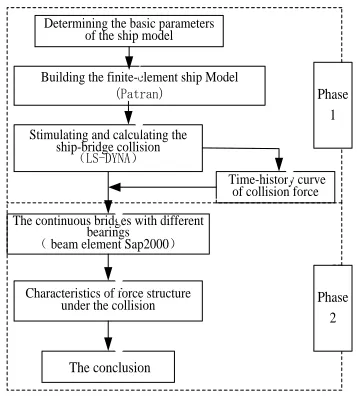
model is used to study the local collision effect. Through the analytical software LS-DYNA, the time-history curve of the collision force under the ship-rigid wall collision is obtained. In this phase, the characteristics of the ship in the collision, not the response of the bridge structures, need more attention[4]. It is conservative to replacing the ship-bridge collision force with the time-history curve of the ship-rigid wall collision force. In phase 2, put the time-history curve of the ship-rigid wall collision force into the continuous bridge beam element model built with SAP2000 for dynamic response analysis of the whole ship. Then the responses of major parts are obtained and a conclusion is drawn.
Building the finite-element ship Model
(Patran)
Stimulating and calculating the ship-bridge collision
(LS-DYNA)
The continuous bridges with different bearings
( beam element Sap2000)
Characteristics of force structure under the collision
The conclusion
Time-history curve of collision force Determining the basic parameters
of the ship model
Phase 1
Phase 2
Figure 1: Flow Chart Of Simplified Analysis Method
3. CALCULATION EXAMPLES AND
ANALYSIS
3.1 The Finite Element Model Of The Ship The ship used in the article is cargo ship 10000DWT, whose parameters are shown in Table 1. The ship bow, which produces a large deformation to energy consumption in the collision, is stimulated more intensively with elastic-plastic steel as the stimulation material, whose parameters are identical to that of the actual bow. The other parts of the ship, far from the collision area, are unlikely to deform. In order to save the effort of model building, calculating time and memory space, the structure is stimulated with relatively rough finite-element mesh and rigid material.
Since the collision is transient and the steel of the bow has large strain rate, the influence of material strain rate should be taken into consideration. In this paper, Cowper-Symonds model is used for the
strain rate, which is [5]
' 1/
0
/ 1 ( / ) q
e e D
σ σ = + ε⋅ , and the strain rate
coefficient of the mild steel in the ship bow
isD=40.4 , q=5.
[image:2.612.104.285.271.470.2]In this course, MSC. PATRAN and FEMB are used in early phase, and the model of Patran is shown in Figure 2. Then LS-DYNA is used as the solver for the analog stimulation of the ship-rigid wall collision.
Table 1
Major Parameters And Size Of The Colliding Ship
Ship type
Length( m)
Breadth (m)
Depth( m)
Draught (m)
Load (t)
Displacem ent (t)
Cargo
ship 121.0 20.0 9.0 6.0 9440 11900
Figure 2: The Finite Element Of Ship
3.2 The Finite Element Model Of The
Continuous Bridges With Different Bearing Type
The bridge used in the calculation is one
continuous bridge in China with the spans of 5×
180 180 180 180 180 180 180 180 180 180 180 180
200 200 200 200 200 200
5¡ Á5000=25000
[image:3.612.94.295.64.545.2]1# 2# 3# 4# 5#
Figure 3: Elevation Of The 50-Meter Continuous Bridge
Figure 4: Elevation And Side View Of No. 3 Pier
(Unit: Cm)
Figure 5: The Finite Element Model Of The Whole Bridge
(a) Model 1: No. 4 pier of this model is fixed while the others are mobile. All the piers are fixed with pot rubber bearings. The ship will hit the abutment of No. 3 pier. The longitudinal friction of bearing should be considered. Model 1is shown as in Figure6.
1# 2# 3# 4# 5# 6#
[image:3.612.330.506.558.651.2]mobile bearing fixed bearing
Figure 6: Calculation Diagram Of Model 1
(b) Model 2: The bearings in this model are all lead rubber, and the ship will hit the abutment of No. 3 pier.
(c) Model3: The bearings in this model are all hyperboloid spheroid, and the ship will also hit the abutment of No. 3 pier.
3.3 The Three Different Bearing Types And Their Stimulation Parameters
The bridge bearing is an important part joining the upper and lower structure of a bridge, which has been proven by large amount of experiment analysis. The dynamic characteristic of the bearing has great influence on the dynamic responses of the bridge structure. Many scholars both home and abroad have conducted a series studies on the characteristics and calculation modes of different types of bearings[6-9]. There are many types of bridge bearings, and the followings types are widely used in projects: plate rubber bearing, polytetrafluoroethylene (PTFE) sliding bearing, pot rubber bearing, seismic resistance pot rubber bearing, hyperboloid bearing, lead rubber bearing, spheroid bearing and arch steel plate bearing[10], etc.. This article mainly studies the influences that the three different bearings, namely, pot rubber bearing, hyperboloid bearing and lead rubber bearing, have on the responses of the key structures of a continuous bridge under a collision.
3.3.1 Pot rubber bearing and its stimulation parameters
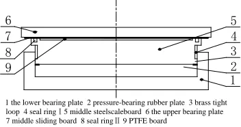
The ordinary rubber bearing is shown in Figure7, whose mechanical property is linear elasticity. The relative displacement between the upper and lower structure of the bridge is realized through the ultralow friction coefficient between the PTFE plate and the steel plate. It is mainly characterized by low damping. And large bearing displacement may be produced even under low horizontal loading.
6 7 8 9
5 4 3 2 1
1 the lower bearing plate 2 pressure-bearing rubber plate 3 brass tight loop 4 seal ringⅠ5 middle steelscaleboard 6 the upper bearing plate 7 middle sliding board 8 seal ringⅡ 9 PTFE board
Figure 7: Ordinary Rubber Bearing
[image:3.612.95.296.626.695.2]ISSN: 1992-8645 www.jatit.org E-ISSN: 1817-3195
rigidity and the smooth value is 10 so as to guarantee iteration convergence.
3.3.2 Lead rubber bearing and its parameters
The lead rubber bearing is a kind of shock resistant bearing with lead stick put into the ordinary rubber bearing to improve its hysteretic energy capability. The lead rubber bearing not only meets the rigidity requirements of static load, but also provides the yield rigidity required by earthquake load. Under a relatively high earthquake load, the lead rubber bearing is barely affected by horizontal loading with its excellent hysteretic characteristics. It can consume large amount of vibrational energy and restore its force with the function of the rubber. The hysteretic curve area of the lead rubber bearing is much bigger than that of ordinary rubber bearings, and its initial rigidity is ten times as much as that of ordinary rubber bearings, and its post-yield rigidity is close to the shearing rigidity of ordinary rubber bearings.
The great many power performance experiment have proven that the hysteretic curve of lead rubber bearings is bilinear, therefore, the following bilinear resilience model is used for the earthquake response analysis of lead rubber bearings. In Fig. 8, K refers
to the rigidity on elastic stage, xy is yield
displacement, Kp is the rigidity on plastic stage, Xo
is the point of speed changing symbol, and
y y
Q =Kx is the yield shearing force.
F(χ)(shearing force)
B(Ⅰ)
A(Ⅰ)
Qy
F(Ⅰ)
E(Ⅱ)
D(Ⅱ)
- Qy C(Ⅱ)
-¦ Ö0 -¦ Öy
¦ Öy ¦ Ö0
K
¦ Ö
[image:4.612.335.498.192.287.2](relative displacement)
Figure 8: The Bilinear Resilience Model
The yield force of the lead rubber bearing in this article is 561KN, the initial rigidity is 30100kKN/m, and the yield rate (the rate between the initial yield rigidity and post-yield rigidity) is 0.1528.
3.3.3 Hyperboloid bearing and its stimulation parameters
Hyperboloid bearing belongs to the category of sliding bearing and is composed of upper bearing plate with a sliding spherical surface, a bispherical middle bearing plate, a lower bearing plate with rotating spherical surface and a ring cuff, as is shown in Fig. 9. When the structure receives
relatively low ground drive, the ring cuff’s contraint on the upper and lower plates prevents the upper structure from sliding and thus keeps the structure stable; while the drive exceeds the limit, the bolt joining the ring cuff and the upper bearing plate will be cut and sliding will happen. At this point, the force transmitted to the upper structure will not increase with the ground drive.
upper bear i ng pl at e mi ddl e bear i ng pl at e l ower bear i ng pl at e
r i ng cuf f
[image:4.612.97.283.459.554.2]sl i di ng spher i cal sur f ace r ot at i ng spher i cal sur f ace
Figure 9: Hyperboloid Spheroid Bearing
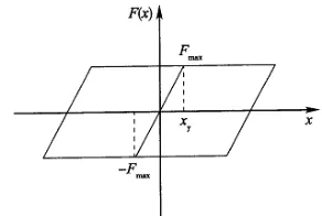
The hysteretic curve of hyperboloid spheroid bearing resembles the stress-strain relationship of elastic-perfectly plastic material, and the resilience model used in this article is shown as follows. In
Fig. 10, Fx refers to the critical friction force, x
refers to the relative displacement of the upper
structure and the pier top, and xy is critical
displacement with the limit from 0.002 to 0.005 meter. According to the condition that the maximum value of elastic restoring force equal to the critical sliding friction force, the critical
displacement value d y
u R x
k
=
, in which ud refers to
the sliding friction coefficient, which is usually 0.02, and R refers to the gravity that the upper structure has on the bearing (KN).
Figure 10: Resilience Model Of The Sliding Bearing
[image:4.612.342.488.503.601.2]3.4 Calculation And Result Analysis Of Bridge Dynamic Response
The mechanism of ship-bridge collision is very complicated, and the slight difference of collision position or the collision angle may lead to a quite different result[15]. The collision angle refers to the included angle between the ship axis and the transverse direction of bridge pier. The finite-element ship model hits the above three continuous bridge models at the constant speed of 4m/s with
different angles of 0º, 2 º, 4 º till 50 º. According
to the simplified analysis and numerical stimulation calculation analysis, we can get the collision force time-history of the ship under collision. Put it as the
input load into the bridge calculation model built with SAP2000 to analyze whole bridge dynamic response, and we will get the different responses of the key structure of the continuous bridges with the above three different bearings with different collision angles. The key structure includes the maximum abutment displacement, maximum pier top displacement, maximum bearing shearing force, maximum pier bottom shearing force and moment area, maximum pile top shearing force and moment area, etc. The curves of the response are shown as follows in Figure11-18.
0 10 20 30 40 50
5.0x10³ 1.0x10⁴ 1.5x10⁴ 2.0x10⁴ 2.5x10⁴ 3.0x10⁴
maximum ship collision force fitting straignt line Y = 31878.58889-501.52765 * X R=0.95228 m axi m um s hi p c ol li si on f or ce fr om di ff er ent c ol li si on a ngl es ( kN )
different angles of ship-bridge collision(°)
0 10 20 30 40 50
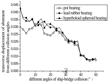
0.000 0.005 0.010 0.015 0.020 0.025 0.030 0.035 0.040 0.045 pot bearing lead rubber bearing hyperboloid spheroid bearing
t ra ns ve rs e di spl ac em ent of a but m ent fr om di ff er ent c ol li si on a ngl es ( m)
[image:5.612.318.505.258.397.2]different angles of ship-bridge collision(°)
[image:5.612.100.287.262.394.2]Figure 11: The Maximum Ship Collision Force With Different Angles
Figure 12: The Maximum Transverse Displacement Of Pile Cap With Different Angles
0 10 20 30 40 50
0.00 0.02 0.04 0.06 0.08
0.10 pot bearing
lead rubber bearing hyperboloid spheroid bearing
tr ans ve rs e di spl ac em ent of pi er t op f rom di ff er ent c ol li si on a ngl es ( m )
different angles of ship-bridge collision(° )
0 10 20 30 40 50 0.0 5.0x10² 1.0x10³ 1.5x10³ 2.0x10³ 2.5x10³ 3.0x10³ 3.5x10³ pot bearing lead rubber bearing hyperboloid spheroid bearing
tr ans ve rs e s he ar ing f or ce of pi er bot tom f rom di ff er ent c ol li si on a ngl es ( kN )
different angles of ship-bridge collision(° )
Figure 13: The Maximum Transverse Displacement Of The Pile Top With Different Angles
ISSN: 1992-8645 www.jatit.org E-ISSN: 1817-3195
0 10 20 30 40 50 0.0 2.0x10³ 4.0x10³ 6.0x10³ 8.0x10³ 1.0x10⁴ 1.2x10⁴ 1.4x10⁴ 1.6x10⁴ pot bearing lead rubber bearing hyperboloid spheroid bearing
tr ans ve rs e m om ent a re a of pi er bot tom f rom di ff er ent c ol li si on a ngl es ( kN ، m )
different collision angles of ship-bridge collision( °)
0 10 20 30 40 50 0 1x10³ 2x10³ 3x10³ 4x10³ 5x10³ 6x10³ 7x10³ 8x10³ 9x10³ 1x10⁴ pot bearing lead rubber bearing hyperboloid spheroid bearing
tr ans ve rs e s he ar ing f or ce of pi le t op fr om di ff er ent c ol li si on a ngl es ( kN )
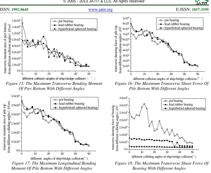
[image:6.612.91.526.62.419.2]different collision angles of ship-bridge collision(°) Figure 15: The Maximum Transverse Bending Moment
Of Pier Bottom With Different Angles
Figure 16: The Maximum Transverse Shear Force Of Pile Bottom With Different Angles
0 10 20 30 40 50 0.0 5.0x10³ 1.0x10⁴ 1.5x10⁴ 2.0x10⁴ 2.5x10⁴ 3.0x10⁴ pot bearing lead rubber bearing hyperboloid spheroid bearing
t ran sv er se m om en t ar ea o f p il e t op f rom di ff er ent c ol li di ng a ngl es ( kN ، m )
different angles of ship-bridge collision(° )
0 10 20 30 40 50 0.0 5.0x10² 1.0x10³ 1.5x10³ 2.0x10³ 2.5x10³ 3.0x10³ 3.5x10³ pot bearing lead rubber bearing hyperboloid spheroid bearing
tr ans ve rs e s he ar ing f or ce of be ar ing f rom di ff er ent c ol li di ng a ngl es ( kN )
[image:6.612.98.315.71.403.2]different colliding angles of ship-bridge collision(° )
Figure 17: The Maximum Longitudinal Bending Moment Of Pile Bottom With Different Angles
Figure 18: The Maximum Transverse Shear Force Of Bearing With Different Angles
The calculation result indicates that the maximum collision force drops with the increase of the colliding angle. But the responses of bridge key structures do not decrease with the increase of the colliding angle. And there is a large difference among the responses of the bridges with three different bearings. The changing rules are summarized as follows:
(1) From Figure11, with the increase of the collision angle, the maximum ship collision force decreased linearly, while the responses of the key bridge structures do not decrease with it. From
Figure12, when the transverse abutment
displacement response of continuous bridge with the pot bearing reaches the maximum value under
the10º collision angle, the curve around 25º has a
slight rally and then show a oscillation decrease tendency. The curve of the maximum abutment transverse displacement of the bridges with lead bearing and hyperboloid spheroid bearing are on a stable declining tendency and without obvious fluctuation, the maximum value will appear in the
0º collision angle. The transverse rigidity of the pot
bearing is far greater than that of the lead bearing and hyperboloid spheroid bearing, so it joins the girder and the lower part much tighter and makes
the piers as a whole resist together against the
collision force. When 0º ship-bridge collision
happens, the ship hits against the bridge which is much heavier and will produce a large deformation while the abutment produces a slight deformation. When the transverse rigidity of the bearing is small, yielding happens to the lead bearing, which leads to the sliding of the upper structure and the increasing of the abutment displacement and thus the deformation of the collision ship bow is small.
(2) From Figure14 and Figure15, with the increase of the collision angle, the maximum shearing force of pier bottom of pot bearing bridge is less likely to fluctuate and is more stable. If the
angle is less than 10º in a collision against the lead
bearing bridge, with the increase of the colliding angle, the maximum transverse shearing force of the pier bottom is in the trend of gradual decrease
and it will witness obvious fluctuation at about 15º,
[image:6.612.320.516.265.390.2]transverse shearing force of the pier bottom of hyperboloid spheroid bearing bridge is the largest.
From the above three conditions, it can be found that the transverse yielding rigidity of hyperboloid spheroid bearing is small since the bridge is
small-spanned. When collision happens at 0 º, the
maximum transverse shearing force of pier bottom of hyperboloid spheroid bearing bridge is 3480KN, 4% less than the response value 3635KN when the ship hits a single pier. This explains that when the pier yielding rigidity is small, and the joining rigidity of the lower and upper part is low, the vibration of the upper part on the pier is not big under a ship collision, which can be regarded as the action between the single pier and the ship. When the bearing rigidity of, for example, a pot bearing, is large, that is to say, the upper and lower parts are tightly connected, the upper structure changes the basic vibrating frequency of the pier shaft and the boundary conditions, and reduces the responses of the pier stud under the ship collision force. It is also found that the bigger the transverse rigidity of the bearing, the smoother the curve, and the smaller the transvers rigidity, the more obvious the curve fluctuation.
(3) From Figure16 and Figure17, with the increase of the colliding angle, the maximum transverse shearing force of the pier top of pot bearing bridge does not on monotone decrease, and its variation tendency resembles that of the transverse moment area of pier tops. If collision
happens within the angle from 10º to 15º, the piles
are very likely to be damaged by shearing force. The maximum transverse shearing force of the pier top of the lead bearing bridge is on smooth decrease and without evident fluctuation. The maximum appears when the collision happens from the angle of zero degree, and the shearing force stays strong and the pile foundation is in danger when the
colliding angle is within 15º. The response curves
of hyperboloid spheroid bearing bridge and lead bearing bridge are highly similar. Since the transverse rigidity of the pot bearing is high, the collision force transmits both upward to the upper structure and downward to the pile foundation. But with the quake insulation bearing, the collision force is mostly transmitted to the pile foundation, and leads to obvious responses from the pile foundations of lead bearing bridge and hyperboloid spheroid bearing bridge.
From the above three conditions, it is found that the response to the collision is the smallest with the pot bearing bridge. When the upper part and the
lower part is tightly connected, the full bridge structure reacts with the ship, and the ship is damaged while the bridge responses slightly. The type of the bearings has much weaker influence on the pile response than on the piers.
(4) From Figure18, with the increase of the collision angle, the maximum transverse shearing force of pot bearing is not on monotone decrease,
but abruptly increases at the angle between 10º to
15º and gradually decreases after that. When the
angle is between10º and 15º, the bearings are easy
to damage. With the increase of the collision angle, the maximum transverse shearing force of the lead bearing decreases gradually and the absolute value of the slope will be very small. The response value of the transverse shearing force of hyperboloid spheroid bearing is the smallest. The transverse shearing force of pot bearing is much bigger than that of the lead bearing and the hyperboloid bearing.
4. CONCLUSION
(1) In this article, a simplified method of ship-bridge collision is proposed. The time-history of the collision force under ship-rigid wall collision, as the dynamic load, is put into the finite-element model of the bridge. Then the influence of the bearing types on the responses of the key bridge structures is studied to prove the feasibility of the simplified method.
(2) The responses of the key bridge structures with three different bearings are compared and analyzed. It is found that the responses of the key structures of the pot bearing continuous bridge are the smallest. That is to say, when the upper part and lower part are tightly connected, all the bridge piers as a whole resist together against the collision force and the key structures of the bridge respond slightly.
ISSN: 1992-8645 www.jatit.org E-ISSN: 1817-3195
response of the piles is much weaker than that of the piers.
REFERENCES
[1] D. Wang, Q. Feng, X. Ling, et al., “State-of-the-art of nonlinear seismic response analysis of RC
bridge”, Earthquake Engineering and
Engineering Vibration, Vol. 1,2002.
[2] J. Wang, J. Li, L. Fan, “Effects of Restrainers Seismic Responses of Continuous Beam
Bridge”, Journal of the China Railway Society,
Vol. 30, No.3, 2003, pp. 71-77.
[3] Z. Li, F. Yue, L. Zhou. “Equivalent Kelvin Impact Model for Pounding Analysis of Bridges During
Earthquake”, Engineering Mechanics, Vol. 25,
No.4, 2008, pp. 138-133.
[4] W. Fan, W. Yuan, L. Li, Z. Yang, “Practical Procedure for Dynamic Response Analysis of Thousand-meter Scale Cable-stayed Bridge
Subjected to Ship Collision”, Journal of Wuhan
University of Technology, Vol. 34, No.4, 2010, pp. 671-673.
[5] American Association of State Highway and
Transportation Officials(AASHTO). Guide
Specification and Commentary for Vessel Collision Design of Highway Bridges, Washington,D.C.,1991.
[6] Constantinou M, Mokha A, Reinhorn A, “Teflon
Bearings in Base Isolation Ⅱ :Modeling”,
J.Struct,Engng, Vol. 116, No.2, 1990, pp. 455-457.
[7] Luciana R, Barroso, “Perfomance Evaluation of Vibration Cotrolled Steel Structures Under Seismic Loading”, Stanford University,1999. [8] S. Xue, X. Li, Y. Cai, “Experiments on a New
Type of Seismic Isolation Bearing Combined with Teflon Frictional Sliding System and
Springs”, Jounal of Beijing University of
Technology, Vol. 35, No.2, 2009, pp. 168-173. [9] C. Zeng, Z. Tao, W. Pan, et al., “Research of the
Influence Factors of the Friction Coefficient PTFE and Stainless Steel Plate of FPE”,
Earthquake Resistant Engineering and Retrofitting, Vol. 31, No.1, 2009, pp. 59-63. [10] S. Liao, Z. Wu, J. Jin, “Rubber Bridge Bearing”.
![Assessment of Physiological Health Status in Relations to Different Anthropometric and Cardio respiratory Measures of Head Supported Load Carrying Male Porters of Sikkim, India [Article Retracted]](data:image/gif;base64,R0lGODlhAQABAIAAAP///wAAACH5BAEAAAAALAAAAAABAAEAAAICRAEAOw==)