A BASED RULES APPROACH FOR DISTRIBUTED TEST
1
MY El HASSAN CHARAF, 2MOHAMMED BENATTOU, 3SALMA AZZOUZI
Laboratory of Research in Computer Science and Telecommunication Faculty of Science Ibn Tofail University
Kenitra, Morocco
ABSTRACT
Since testing is a continuous activity throughout the entire development process, it is important to take into account the inherent complexity of the distributed systems architecture that require special testing techniques. In fact, in the distributed test context where a set of parallel testers exchange I/O messages to perform the test, some potential problems of coordination can arise amongst remote testers. These problems are usually known as controllability and Observability issues. The emphasis of recent works is focused on the use of rules based systems that describe the system behavior by simple rules which increase the flexibility and easiness of programming. In this paper, we introduce some technical issues for testing distributed frameworks using rules based systems to overcome such problems.
Keywords: Rules-based system; Distributed test; Rules; Controllability and Observability Problems;
Synchronization.
1. INTRODUCTION
Unlike the centralized test where the entire activity of the test (injection of stimulis and observing reactions of the implantation under test) is performed by a single entity, this activity is performed by a set of parallel testers called PTCS (Parallel Test Components) in the distributed context. The difficulty is in ensuring coordination between such PTCs. The coordination between the PTCs produces some problems known as controllability and observability issues that have great influence on several aspects of the testing activity, such as the execution of the test sequences, the fault detectability in the test system and the interpretation of testing results.
As ANSWER to these difficulties, a significant tendency is focused on the use of rules based systems. This kind of systems permits the implementation of highly flexible systems capable of adapting themselves to different situations by seeking to express an automatism in a similar way to as would make it a human being: “IF antecedents THEN consequents”. Additionally, the testers -in such systems- are able to take decisions concerning possible malfunctions and decided if the process of test returns a failed verdict or an accepted one.
In THIS article, we explore the benefits of rule-based multi-agent systems to concept communication between different components of
the distributed test application. We also explain how such systems can avoid the use of the coordination messages and resolve the synchronization problems. By the way, the testers will exchange only some messages called observation messages which will reduce significantly I/O operations and the use of external messages.
This article is organized as follows: The second section describes the architecture, the concept of distributed testing, and the test procedure while referring to the problem of synchronization.
We introduce then in the third section an example of rules generation from a global test sequence. In the fourth section, we present rules and facts as components of a petri net to benefit of its formalism.
The last section describes our rule-based multi-agent system prototype for testing distributed applications.
A. Architecture
The basic idea is to coordinate parallel testers using a communication service in conjunction with the (IUT)1. Each tester interacts with the IUT through a port called the Point of Control and
Observation (PCO)2 and communicates with other testers through a multicast channel (Fig.1).
Figure 1. Test Architecture
An IUT (Implementation Under Test) is the implementation of the distributed application to test. It can be considered as a "black-box", its behavior is known only by interactions through its interfaces with the environment or other systems.
B. Modeling by automaton
To approach the testing process in a formal way, the specification and the IUT must be modeled using the same concepts. The specification of the behavior of a distributed application is described by an automaton with n-port (FSM Finite State Machine) [1] defining inputs and the results expected for each port called PCO.
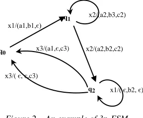
We denote Σk the input alphabet OF the port k (PCO number k) and Γk the output alphabet of the port k. Fig. 2 gives an example of 3p-FSM with Q = {q0, q1, q2,q3}, q0 is the initial state, Σ1 = {x1}, Σ2 = {x2}, Σ3 = {x3}, and Γ1 = {a1,a2,a3 }, Γ2 = { b1,b2,b3}, Γ3 = { c1,c2,c3}.
Figure 2. An example of 3p-FSM
A test sequence of an np-FSM automaton is a sequence in the form: !x1? y1!x2? y2…! xt?yt that for i = 1,..,t : xi є Σ , yi Γk and for each port k |yi ∩Γk| ≤ 1.
• !xi :Denotes sending the message xi to IUT.
2 PCO : Point of Control and Observation
• ?yi :Denotes the reception of messages
belonging to the yi from the IUT.
An example of a TEST sequence of 3p-FSM illustrated in Fig. 2 is:
!x1?{a1,b1,є}!x2?{a2,b3,c2}!x2?{a2,b2,c2}!x1?{є, b2, є}!x3 ?{a1,є,c3}. (1)
Generally, test sequences are generated from the specification of the IUT and characterized by fault coverage. Several methods exist for generating test sequences from I/O FSM specifications. They are mainly for detecting the following types of fault: output faults, transfer faults or combination of both of them [2].
C. Distributed Test Problems
Many kinds of problems can arise in the distributed test context, we define these notions by referring [3].
1) Controllability Problem
It can be defined from Test System view as capability of a Test System to force the IUT to receive inputs in the given order. Controllability problem arises when Test cannot guarantee that IUT will receive event of transition(i) before event of transition (i+1).
2) Observability Problem
It can be defined from Test System view as capability of a Test System to observe the outputs of the IUT and decide which input is the cause of each output.
For distributed test architecture where a transition contains at most single output for each output, observability problem arises when two consecutive transition (i) and transition(i+1) occurs on the same port k but only one of the transitions has an output in port k and the other one is an empty transition with no output. In this case the Test System cannot decide whether transition(i) or transition(i+1) is the cause of output.
To resolve such problems, authors in [3] propose an algorithm to generate local test sequences from the global test sequence. We will get the following local test sequences by applying the algorithm mentioned above to the global test sequence (1):
w1=!x1?a1?a2?a2!O3!x1?a1,
w2=?b1!O3!x2?b3!x2?b2?b2!C3, (2) w3=?O2?c2?c2?O1?C2!x3?c3 .
q2
x3/(a1,є,c3)
x1/( є,b2, є) x3/( є, є,c3)
q1 x2/(a2,b3,c2)
q0
x1/(a1,b1,є)
x2/(a2,b2,c2) Multicast channel
IUT
PCO
PCO
Tester
Tester
Tester
As shown in the obtained local test sequences, some coordination messages (Ck) are added to the
projections of the global test sequence in each port to avoid both the controllability and observability problems when using the complete test sequence. We notice two kinds of coordination messages:
• C coordination messages for guaranteeing controllability
• O coordination messages for guaranteeing observability. We denote:
• !C{t1,,tr}(!O{t1,,tr} resp.) the sending of a
coordination message (observation message resp.) to the testers t1..tr.
• ?Ct(?Ot resp.) the receipt of a coordination
message (observation message resp.) from the tester t.
3) Synchronization Problem
As explained above, the algorithm in [3] allows the generation of local test sequences to be performed by each tester.
[image:3.612.97.299.370.449.2]
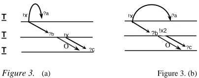
Figure 3. (a) Figure 3. (b)
Each tester is running its local test sequence produced from the global test sequence of the IUT. Thus, the testers are working together but independently, which leads us to manage the problem of synchronization of testers. We will run the first fragments of the local test sequences w1, w2 and w3 defined as follows:
wf1=!x1?a1,
wf2= ?b1!O3!x2, (3) wf3=?O2?c2 .
Running wf1, wf2 and wf3 should give the result shown in Fig. 3(a) but the execution of our prototype provides an incorrect result given in Fig. 3 (b). Indeed, in the last diagram the second tester sends the message x2 to the IUT before the first tester receives the message a1 from the IUT.
So, the execution of local testing is not conform with the specification in (1), where the message ‘x2’ must be sent only if all messages due to the sending of ‘x1’ by the tester-1 are received by the IUT.
In the following of this paper, we will take - for simplicity, the test sequence of 3p-FSM shown in Fig. 2 defined as:
!x1?{a1,b1,є}!x2?{a2,b2,c2}!x3?{є,є,c3}. (4)
D. Related Works
Many works has been made to avoid the problems described in the previous section. Indeed, the author in [4] shows that controllability and observability are indeed resolved if and only if the test system respects some timing constraints. Then the article determines these timing constraints and other timing constraints which optimize the duration of test execution.
In [5], the authors explain how both
controllability and observability problems can be overcame through the use of coordination messages among remote testers.
The work [6] proposes a new method to generate a test sequence utilizing multiple unique input/output (UIO) sequences. The method is essentially guided by the way of minimizing the use of external coordination messages and input/output operations.
In [7], the authors suggest to construct a test or
checking sequence from the specification of the system under test such that it is free from these problems without requiring the use of external coordination messages. In this context, they propose some algorithms for constructing subsequences that eliminate the need for external coordination messages.
Another work [8] shows that the use of
coordination messages can introduce delays and this can cause problems where there are timing constraints. Thus, sometimes it is desired to construct a checking sequence from the specification of the system under test that will be free from controllability and observability problems without requiring the use of external coordination message exchanges. To this end, the authors suggest an algorithm that achieves this.
The main idea in [9],[10],[11] is to construct a test sequence that causes no controllability or observability problems during its application in a distributed test architecture. For some specifications, such test sequence exists where the coordination is achieved via their interactions with the IUT [12]. However, this case is not always true as detailed in [13] and [9].
O O
?c ?c
!x ?b
?a
!x
?b !x ?a
!x
T
T
T
The emphasis of recent works is to minimize the use of external coordination message exchanges among testers [11],[14] or to identify conditions on a given FSM under which controllability and observability problems can be overcome without using external coordination messages [13], [15].
Finally, our work is mainly based on [5], [16] and the algorithm proposed in [3] for writing test coordination procedures in a distributed testing architecture.
The paper can be considered as a continuity of [17] where we propose the use of the MAS (multi-agent system) incorporated with ontology.
2. RULES GENERATION FROM A
GLOBAL TEST SEQUENCE
The basic idea behind introducing the rule’s concept in the distributed test context is that the exchange of messages to perform the test is sequential. In fact, for each transition in the test process, the next messages to be sent to the IUT depend mainly on the previous messages received even from the IUT or from other testers. The idea is to write algorithm to deduce -from the global test sequence- the rules to be respected by the testers to guarantee their coordination. In fact, each rule is composed by two parts, conditions and results. These components are shared between the IUT and the testers as facts.
To communicate with the IUT, the testers follow some instructions described through these rules. When the necessary conditions (facts) have arisen, the tester proceeds in applying results as described in its local rules. Let us take the global test sequence!x1?{a1,b1,є}!x2?{a2,b2,c2}!x3?{є,є,c3} defined in (4). It can be translated on a set of rules as follow:
If the tester T1 send a message x1 to the IUT
(!x1.T1) then the tester T1 will receive a message
a1 from the IUT (?a1.T1) and the tester T2 will receive a message b1 from the IUT (?b1.T2).
If the message a1 is received in the tester T1
(?a1.T1) and the message b1 is received in the
tester T2 (?b1.T2). Then the tester T2 will apply the message x2 to the IUT (!x2.T2).
At this stage, we have an observability problem so we will introduce an observation message O3 to be sent by tester T2 to the tester T3. In this case, the next rule is as follow:
If the tester T2 send a message x2 to the IUT
(!x2.T2) then the tester T1 will receive a message
a2 from the IUT (?a2.T1) and the tester T2 will receive a message b2 from the IUT (?b2.T2) and the tester T3 will receive a message c2 from the
IUT (?c2.T3) and the tester T2 will send an
observation message O3 to tester T3 (!O3.T2).
All these rules can be expressed over each tester as local rules as follows:
! x1.T1 ?a1.T1 ; !x1.T1 ?b1.T2 ;
?a1.T1 !x2.T2 ; ?b1.T2 !x2.T2 ;
!x2.T2 ?a2.T1 ; !x2.T2 ?b2.T2 ; !x2.T2 ?c2.T3 ; !x2.T2 !O3.T2
However, we can notice that the verdict of the test over the whole system can be obtained by calculating if all the local rules have been respected in each tester during the test execution. Thus, in the point of view of the Test system, the coordination is ensured using the global rules as follows:
! x1.T1 ?a1.T1 ^ ?b1.T2,
?a1.T1 ^ ?b1.T2 !x2.T2,
!x2.T2 ?a2.T1^ ?b2.T2 ^?c2.T3 ^ !O3.T2.
In the next subsections, we explain how we can generate (local/global) rules from a given global test sequence.
Let’s take the example of the global test sequence defined in (4). The algorithm [20] generates a matrix of local rules by browsing the‘t’ messages to be sent to the IUT in the global test sequence.The rules will be constructed as follows:
• Each message belonging to yi is a part of a rule in the matrix as a consequence of sending message xi
• Each message belonging to yi is a part of a rule in the matrix as an antecedent of sending message xi+1.
To avoid observation problems, each tester receiving a message h є yi-1 should be able to determinate that h has been sent by IUT after IUT has received xi-1 and before IUT receives xi.
Afterwards, we introduce the observation messages to write rules for avoiding this problem
Therefore, by applying the algorithm [20] to the global test sequence defined in our example, the obtained matrix is a R38 matrix composed by the
elements Rij defined as follows:
R11:! x1.T1?a1.T1 R21: ! x2.T2 ?a2.T1 R31: ! x3.T3?c3.T3
R12:!x1.T1 ?b1.T2 R22: ! x2.T2 ?b2.T2 R32:!x3.T3!O1.T3
R13:?a1.T1 !x2.T2 R23: ! x2.T2 ?c2.T3 R33:!x3.T3!O2.T3
R14:?b1.T2 !x2.T2 R24: ?a2.T1!x3.T3 R34:!O1.T3 ?O3.T1
R15:є R25: ?b2.T2 !x3.T3 R35:!O2.T3 ?O3.T2
R16:є R26: ?c2.T3 !x3.T3 R36:є R17:є R27: ! x2.T2!O3.T2 R37:є R18:є R28: !O3.T2 !O2.T3 R38:є
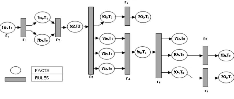
Then, we can deduce facts and global rules from the obtained matrix as:
• F =:{ !x1.T1- ?a1.T1- ?b1.T2- ?a2.T1- ?b2.T2- ?c2.T3-!O3.T2- ?O2.T3-?c3.T3-!O1.T3- !O2.T3-?O3.T1-?O3.T2}
• R= :{r1 - r2 - r3 - r4 - r5 - r6 -r7 -r8}
r1 : ! x1.T1 ?a1.T1 ^ ?b1.T2
r2 : ?a1.T1 ^ ?b1.T2 !x2.T2
r3 : !x2.T2 ?a2.T1^ ?b2.T2 ^?c2.T3 ^ !O3.T2
r4 : ?a2.T1^ ?b2.T2 ^?c2.T3 !x3.T3
r5 : !O3.T2 ?O2.T3
r6 : !x3.T3 ?c3.T3 ^!O1.T3 ^ !O2.T3
r7 : !O1.T3 ?O3.T1
r8 : !O2.T3 ?O3.T2
After obtaining the lists of facts and rules, we
describe in the next section our test model using the Petri Net formalism
3. FORMAL DEFINITION AND BASIC
TERMINOLOGY
A Petri net (also known as a place/transition net or P/T net) is one of several mathematical modelling languages for the description of distributed systems. A Petri net is a directed bipartite graph, in which the nodes represent transitions (i.e. events that may occur, signified by bars) and places (i.e. conditions, signified by circles). [18]
In our case, the places represent facts and transitions represent rules. Let’s define the following structures:
• A: matrix of antecedents, Aij =1 if the fact
fj is antecedent in rule ri else Aij =0
• C: matrix of consequents, Cij =1 if the fact
fj is consequent in rule ri else Cij =0
• M: The state (marking) of a Petri net is defined as:
M: P-> N, i.e., a function mapping the set of places onto {0,1,2, … }.
In our case, this function M is defined as follows:
M: F-> {0,1}, i.e., a function mapping the set of facts onto {0,1}.M0 is the initial state ;
M0= (1,0,0,0,0,0,0,0,0,0,0,0,0,0,0).
[image:5.612.96.506.497.672.2]The next diagram represents facts and rules deduced from the global test sequence (4) by applying the algorithm explained in the previous section.
In our case, the matrices A and C are defined as:
We denote A(.,rj ) (respectively C(.,rj )) the row associated to the rule rj in the matrix of antecedents A (resp. matrix of consequents C).
Sensitized rules: In a Petri net, a rule rj is sensitized for a marking M if and only if M A(.,rj ). The is a vectors comparison and it will be done fact by fact as follows:
In our example, let’s take a marking M=(1,1,1,0,0,0,0,0,0,0,0,0,0,0,0) and calculate if the rules r2 and r3are sensitized for this marking or not. We have A(.,r2) =
(0,1,1,0,0,0,0,0,0,0,0,0,0,0,0) and A(.,r3)=(0,0,0,1,0,0,0,0,0, 0,0,0,0,0,0). By
comparing M with the rows above: M A(.,r2 ) and A(.,r3 ) M , we can deduce that the rule r2 is sensitized for the marking M but the rule r3 is not.
Fired rules: In a Petri net, a sensitized rule rj for
a marking M can be fired and the next marking M is defined as:
The marking vector M is composed by positive or null values because M A(.,rj ) for the sensitized rule rj. In the example above if the rule
rj is fired the next marking will be
M=(1,0,0,1,0,0,0,0,0,0,0,0,0,0,0)
As conclusion, when we have the facts and rules list represented in a matrix form (A,C) and the initial state of the system M0, we can then deduce using simple arithmetic operations the state of the system and decide if some rules can be enabled. In the next section we introduce a rule-based multi agent system that will implement rules and facts described previously.
4. TEST PROTOTYPE
A. Terminology
1) Rule-Based Expert System
A rule based expert system is typically composed of at least three primary components. These are the
knowledge base which is a collection of rules, the inference engine that enables the expert system to draw deductions from the rules in the KB and finally the working memory which contains the data that is received from the user during the expert system session.
2) Rule-Based Multi-Agent System MAGSY
As detailed in [19], the kernel of an agent in MAGSY is a forward-chaining rule interpreter. Therefore, each agent has the problem solving capacity of an expert system. The knowledge of the agents is structured in an object-oriented knowledge representation scheme. There is a global knowledge base which contains the knowledge that may be accessed by all of the agents.
B. Architecture
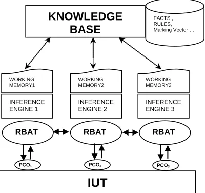
[image:6.612.314.514.407.595.2]A rule-based multi-agent system has been proposed to avoid the synchronization problem described above. It’s mainly based on the use of some agents in the distributed nodes connected to the IUT. Each agent executes only a part of the global reasoning, and diffuses through the network the obtained results. By the way, other agents can use these results to participate in the reasoning.
Figure 5. Architecture Of The Distributed Test System
As shown in fig. 5, the system is composed of the following components:
• The IUT (Implementation Under Test) is the implementation to be tested.
• Some agents RBATi (Rule-Based Agent
Testers) connected to the IUT using a PCOi (Point of Control and Observation) to exchange inputs/outputs messages.
f F, M(f) A(f, rj)
M= M
-
A(.,rj ) + C(.,rj )KNOWLEDGE BASE
IUT
RBAT RBAT RBAT
INFERENCE ENGINE 1
INFERENCE ENGINE 2
INFERENCE ENGINE 3
WORKING MEMORY1
WORKING MEMORY2
WORKING MEMORY3 FACTS , RULES, Marking Vector …
• A global KB (Knowledge Base) that store facts, global rules, RBAT identification and the Marking vector.
Each RBATi uses its inference engine and its working memory to communicate with the KB for making a global reasoning.
C. Test procedure
1) Description
• For sending an input to the IUT, the Rule-Based Agent Tester (RBATi) checks the knowledge base to test if the rule is sensitized using the marking M.
• When an RBATi apply an input to the IUT, the IUT sends some outputs messages to the concerned RBATj.
• After receiving the outputs messages from the IUT, each RBATj check using its forward-chaining rule interpreter (IEj) and its Working Memory (WMj) if the message received is the expected one.
If the result is OK => The RBATj
notifies the Knowledge Base (rule fired).
Else => Test Failed.
• The rules Ri of testers concerned by
validating a rule ri must be fired to decide if the next rule can be sensitized.
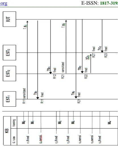
2) Flow Diagram
Let’s take F and R the lists of facts and global rules respectively deduced from the global sequence test (4) and M0 the initial marking.
Since M0 is the initial state, the tester RBAT1 will apply input x1 to the IUT, by the way r1 is fired and the marking will be M1. M1= M0 - A(.,r1 ) + C(.,r1 ) ; M1= (0,1,1,0,0,0,0,0,0,0 ,0,0,0,0,0). When other agent testers receives outputs -induced by applying x1 - from the IUT, each RBATi calculates if the message received is the expected one by checking its local rules. If so, the local rule is fired. Else, the test fails.
[image:7.612.314.522.76.335.2]While all local rules (R11,R12) participating in the global one r2 are fired then the global rule r2 is fired too and the marking is updated to M2=M1-A(.,r2)+C(.,r2). We have A(.,r2)= (0,1,1,0,0,0,0,0,0,0,0,0,0,0,0) and C(.,r2) = (0,0,0,1,0,0,0,0,0,0,0,0,0,0,0). In this case M1= (0,1,1,0,0,0,0 ,0,0,0,0,0,0,0,0) will change to M2=(0,0,0,1,0,0 ,0,0,0,0,0,0,0,0,0) as described in Fig. 6.
Figure 6. The Flow’s Diagram For Exchanges Between Rbati And IUT
Finally, compared to other works that attempt to deduce local test sequences and including some coordination and observation messages to ensure coordination between testers, we suggest in this paper to deduce some rules to be fulfilled by each agent tester to guarantee their coordination.
5. CONCLUSION
The distributed computing becomes the key issue in modern system design. It provides new high possibilities for Internet-based applications. However, in practice the development of distributed component systems is more complex especially where the implementation must take into account some synchronization rules, and the coordination of distributed components. In this article, we present a way to avoid the exchange of the external coordination messages between various components of the distributed test platform.
As explained, this has done by introducing the notions of rule-based multi-agent system to propose an architecture, a model and a method that guarantee the principles of coordination and synchronization in the distributed test context.
The implementation of this approach by writing the kernel of the agent testers using the Prolog formalism, and testing web services applications are the perspectives of our approach.
REFERENCES
[1] A. Gill, “Introduction to the theory of finite-state machines”, Mc Graw-Hill, New Yor- USA, 1962.
[2] A.Petrenko,G.v. Bochmann,M.Yao, “On fault coverage of tests for finite state specifications”,Computer Networks and ISDN System 29,1996,pp.81-106.
[3] O. Rafiq and L. Cacciari, “Coordination algorithm for distributed testing” ,The Journal
of Supercomputing,Volume 24, Number 2, pp
203-211, doi: 10.1023/A:1021759127956 , 2003.
[4] A. Khoumsi, “A Temporal approach for testing distributed systems”, IEEE Transactions on Software Engineering, Nov.2002, vol. 28, no.11, pp. 1085-1103, doi:10.1109/TSE.,2002.1049406.
[5] M.Benattou, L. Cacciari, R. Pasini and O. Rafiq, “Principles and tools for testing open distributed”,Proceedings of the IFIP TC6 12th International Workshop on Testing Communicating Systems. Method and Applications, 1999. p.77-92.
[6] W. y. Liu, H. w. Zeng and H.k. Miao, “Multiple UIO-based test sequence generation for distributed systems” , Journal of Shanghai
University (English Edition), Volume 12,
November 2007,Number 5, pp 438-443, doi: 10.1007/s11741-008-0512-3.
[7] J. Chen, R. M. Hierons and H. Ural, “Testing in the distributed test architecture: formal methods and testing”,Lecture Notes in Computer Science,
2008, Volume 4949/2008, 157-183, doi:
10.1007/978-3-540-78917-8_5.
[8] R. M. Hierons and H. Ural, “Checking
sequences for distributed test architectures”,
Distributed Computing, Volume 21,April 2008, Number 3,pp 223-238,doi: 10.1007/s00446-008-0062-4.
[9] K.C Tai and Y.C Young: “Synchronizable test sequences of finite state machines”,Computer Networks 13. 1111-1134 (1998).
[10]G.Luo, R. Dssouli and G.v Bochmann:
“Generating synchronizable test sequences based on finite state machine with distributed ports”In the 6th IFIP workshop on protocol Test Systems, pp.139-153. Elsevier (1993).
[11]R.M Hierons.”Testing a distributed
system:Generating minimal synchronized test sequences that detect output-shifting faults”,
Information and Software technology ,43(9):551-560,2001.
[12]G.Luo , R. Dssouli, G.v. Bochmann, P.
Venkatram and A. Ghedamsi:”,Test generation with respect to distributed interfaces, 16,119-132 (1994).
[13]J.Chen,R.M. Hierons, and H.Ural. “Conditions for resolving observability problems in distributed testing”,In 24rd IFIP International Conference on Formal Techniques for Networked and Distributed Systems (FORTE
2004), volume 3731 of LNCS, pages
229-242.Springer-Verlag, 2004.
[14]L. Cacciari and O.Rafiq. “Controllability and observability in distributed testing”, Information and Software technology,41:767-780,1999. [15]J.Chen,R.M. Hierons, and H.Ural. “Resolving
observability problems in distributed test
architecture”,25rd IFIP International
Conference on Formal Techniques for Networked and Distributed Systems (FORTE
2005), volume 3731 of LNCS, pages
219-232.Springer-Verlag, 2005.
[16]O. Rafiq, L. Cacciari and M. Benattou,
“Coordination Issues in Distributed Testing”,Proceeding of the fifth International Conference on Parallel and Distributed Processing Techniques and Applications (PDPTA'99, USA: CSREA Press) pp: 793-799.
[17]H. Charaf, M. Benattou, S. Azzouzi, J.
Abouchabaka, “Using an Ontology for Modeling the Communication in the Distributed Test” , The 3th International Conference on Web and Information Technologies June, 2010, Marrakech – Morocco.
[18]J.L.Peterson."Petri net theory and the modeling of systems",Prentice Hall,Inc Englewood Cliffs,
1981.
[19]C.Bǎdicǎ, L. Braubach and A. Paschke “Rule-based distributed and agent systems”, Rule-Based Reasoning, Programming, and Applications Lecture Notes in Computer Science, 2011, Volume 6826/2011, 3-28