205
NUMERICAL SIMULATION STUDY OF AIR DISTRIBUTION
LAW OF AIR PRESSURE SYSTEM IN THE MINE REFUGE
CHAMBER
FANGWEI LI, *LONGZHE JIN, ZINA ZHAN
Civil and Environment Engineering School, University of Science and Technology Beijing, 100083, Beijing, China
*Corresponding Author
ABSTRACT
During the mine disaster, the refuge chamber becomes a living space for persons in distress, and it is an important topic to ensure the supply of oxygen in the refuge space in the study of the environment control of refuge chamber and survival support. Through the combination of RNG k-ε turbulence model, finite-volume discretion method and SIMPLE algorithm, the three-dimensional turbulence mathematics, physics models of refuge chamber air flow under air pressure and oxygen supply conditions are established, and corresponding laws are analyzed and the main parameters in environment control are determined, providing a theoretical basis for the design and layout of the refuge chamber.
Keywords: Refuge Chamber, Air Pressure, Oxygen Supply System; Air Distribution Law, Numerical
Simulation
1. INTRODUCTION
According to statistics and rescue experience for coalmine accidents, the miners, who are dying immediately from injuries such as explosion and collapse on the first site when the mine accidents happen, account for around 30% of total death toll. Most of miners die because they are unable timely to evacuate to safe area or go up due to oxygen depletion, high-concentration poisonous and pernicious gases in nearby areas, or their no timely evacuation to safe areas because escape roads are blocked up by explosion. Thus, it is the most direct reason causing casualties that miners who are unable to transfer are exposed in the poisonous and pernicious gases in coalmine accidents [1, 2].
Based on above considerations, if there are the confined spaces (refuge chambers) for emergency refuge to maintain refugees’ survival safeguard in a certain time, the survival probability can be improved greatly for the trapped personnel by contacting and assisting outside rescue by communication device [3]. In the refuge chamber, oxygen concentration goes down, carbon dioxide goes up, and temperature and humidity lose balance with human body’s metabolism. However, air quality in refuge chamber concerns personnel’ comfort and health, and affects energy consumption in the chamber. Thus, good air flow way is the foundation to realize rational distribution of
pollutants such as temperature, humidity, oxygen and carbon dioxide.
Indoor air flow is complicated. No doubt, modern computer technology is an instrument for air flow in the numerical simulation lab. The CFD method is used to study different physical conditions and model configurations, with less time and research cost [4]. Nielson [5] is the one who applied the DFD method to air flow simulation in the lab in the earliest time. In more than ten years after that, developed countries also put in a lot of manpower, material and financial resources to energy saving and improvement of operational efficiency of the entirely society, and had achieved a certain results. The US is one of countries which apply CFD technology in the earlier time [6], and it is originated from the US space and national defense fields at the earliest. The American National Standards Institute (ANSI) also established a special research institute to study the CFD technology. Besides that, ASHARE also established related research institute in 1989 [7], and organized and completed the task of the Numerical Calculation of Indoor Air Flow. They studied a lot of related issues about the indoor air flow simulated by CFD method.
206 chamber which is a special survival space involved in many factors, the research on its air distribution is still in the blank stage, and further deep analysis and study are needed for that. For this reason, we have studied the indoor air distribution in the refuge chamber through designs of different oxygen-supply, purification and temperature-humidity schemes as well as application of Fluent software, and summed up factors and their law influencing distribution of oxygen and carbon dioxide. This will offer the theoretical basis for the future design and application of the refuge chamber.
2. ANALYSIS OF AIR DISTURBANCE
SOURCE IN REFUGE CHAMBER
The air pressure and oxygen supply system in the refuge chamber consists of an air pressure pipe and a return air pipe. The fresh air is introduced by the air pressure pipe, after the pressure-reduction handling through air pressure control device, the air is distributed uniformly and the chamber is kept under positive pressure through the air-arrangement pipeline, to ensure air quality and maintain the body's normal life activities of the persons in distress [8].
Because the air is introduced through the air-supply pipeline, the volume of the air has a major impact on the persons in distress. As the survival area of the refuge chamber is the main activity area for the refuge persons, it is assumed the volume of air supplied for each refuge person is 150L/min when the survival area is taken as the study objective, and by referring to the methods mentioned in Reference [8], the volume of air is calculated as follows:
Q R K K
Qa1 1 2 (1) Where, Qa1represents the required volume of air
for the survival area, L/min; K1 represents the air
leakage coefficient of the air pressure pipeline, which can be about 1.2; K2 presents the uneven
coefficient of the refuge persons, which can be 1.2; R represents the total number of persons in the refuge chamber, which can be 100; Q represents the volume of air supplied for each person, which can be 150L/min. Therefore the volume of air required for the survival area is 21600 L/min. The diffused air arrangement is employed in the pipeline of air pressure system, to achieve uniform air arrangement and bring ease and freedom to the persons.
3. THE ESTABLISHMENT OF
COMPUTATIONAL MODEL OF THE REFUGE CHAMBER
3.1 The establishment of numerical model The primary physical laws of conservation required to be abided in fluid flow include law of conservation of mass and law of conservation of momentum. As this article focuses on the study of the law of distribution of air in the refuge chamber, containing different components of mixtures and inter-reaction in air flow, the system shall also abide to the law of conservation of components and law of conservation of energy. For the state of air flow, it is generally the turbulent state, and thus the turbulent transport equations shall also be included in the system. Each control equation is discussed in detail as follows [9]:
1) The mass conservation equation
For the state of air flow in the refuge chamber, the general flow rate is the low-speed flow less than 10m/s, and thus it can be taken as that the air is in the stable and incompressible state, i.e.:
0 z y x (2) Where, ρ is the density, υ, ν and ω are the three-dimensional speed, x, y and z is the three-dimensional coordinates
2) Momentum conservation equation
As the air belongs to Newtonian fluid, i.e., the viscous stress τ shall be proportional to the deformation rate of the fluid, the momentum conservation equation applies to all the directions of x, y and z, and it is called N-S equation totally, that is: x S x p grad div u div
t
) ( ) ( ) ( (3) y S y p grad div u div
t
() ( ) ( ) (4) z S z p grad div u div
t
() ( ) ( ) (5) Where, p is the pressure on the fluid unit; u is speed vector; Fx, Fy and Fz are the volume force on
the fluid unit, when only gravity occurs, Fx=Fy=0 ,Fz=ρg; the signals Sx, Sy and Sz are the general
source terms, Sx Fx sx , Sy Fy sy ,
z z
z F s
S , and generally s
x, sy and sz are lower
207 3) Constituent mass conservation equation The mass conservation equation refers to the change rate of mass of some chemical constituent to time, and it should equal the single diffusion flow and chemical production rate of the entire interface. So the constituent mass conservation equation is:
s s s
s
s div uc divD grad c S
t
c
(6) Where, cs is volume concentration, ρcs is mass
concentration, Ds is diffusion coefficient of the
constituent, Ss is the generation of chemical reaction
in unit time and volume. In this paper, the constituents in air mainly include N2, O2, CO2 and H2O. The process of CO2 purification includes the
chemical reaction of LiOH and CO2. O H CO Li CO
LiOH 2 2 3 2
2 (7)
4) Energy conservation law
The energy conservation law is the one that the heat-exchange flow system should satisfy. It means the increment rate of energy in the fluid unit is equal to net heat flow into the unit plus the work that area and volume force do to the fluid unit, and its equation is:
T p S gradT c k div T div t T (8) Where, cp is specific heat (J/kg·K); T isthermodynamic temperature (K) ;k is coefficient of heat transfer; ST is the inner heat source and heat
energy transferred from mechanical energy in the fluid.
5) Turbulence control equation
For the present level of the computer can not be used for the simulation through N-S equation, generally the average time processing method is employed for the transient N-S equation, and the turbulence equation reflecting the turbulence characteristics is supplemented, such as the commonly used turbulence k-ε equation, i.e., turbulence kinetic energy k transport equation and the turbulent dissipation rate ε transport equation:
Turbulence kinetic energy k transport equation is:
G t k
t gradk P
div uk div t
k
(9) Turbulent dissipation rate ε transport equation:
G t t P K C k C grad div u div t 1 2 2 (10) Where, Cμ, σk, σε, C1 and C2 are constants,
t C k2
In summary, integrate formula 2-10 together, a total of nine equations, the unknown terms can be calculated separately. In the process of numerical
simulation of turbulence, the choice of turbulence model is very important, in this article, the RNG k-ε
model is chosen as a turbulence model, and the wall function method is employed to deal with flow in the near wall regions.
3.2 The establishment of physical model 1) The choice of study objective and the establishment of model
Depending on the differences of the functions of areas in the refuge chamber, the refuge chamber can be divided inward and outward into buffer area and survival area. As the environmental parameters of the living area is closely related with human health, the main equipment in the refuge chamber are all arranged in the living area, and considering the complex structure of the refuge chamber, it is quite difficult to build the model according to the overall structure. Therefore, the living area in the refuge chamber is selected finally as the study objective of this article to build the model.
[image:3.612.314.524.344.473.2]Kp=7850 α=45° R=10000
Figure 1 Floor Plan Of The Survival Area In The Refuge Chamber
Figure 2 Base Model-Axonometric Drawing
The volume grid of TGrid( Tet/Hybrid)
[image:3.612.92.301.590.700.2]208
Figure 3 Base Model-Left Elevation Of Grid Division
[image:4.612.88.527.41.787.2]2) The setting of boundary conditions The mine refuge chamber can accommodate 100 persons at most, the survival time is 96 h, and the total square of the living area is 117.92 m2, with a length of 27.8 m, width 4.4 m, and height of 3.8 m. The sectional shape is semicircle, the radius of which is 2.2 m the height of the straight wall is 1.6 m. The air arrangement pipeline in the refuge chamber is 2.7 m in height, a pipeline with a length of 200 mm is used for the extended connection on both side of the pipeline, a air-arrangement hole is equipped in the middle of each section of pipeline, with 5 for a single, and 11 in all, the branch pipe for the connection of each air arrangement hole is 200 mm in length, with a diameter of 75 mm approximately, and meanwhile each section of the pipeline is about 3.0 m and is connected with the flange.
Table 1 Table On The Main Parameters
Positions Boundary types
Temperat
ure Components
Turbule nce strength
Air pressure
inlet
Speed inlet
v=7.55m/s 21℃
21% of O2
5% 0.5% of CO2
0.5% of H2O
78% of N2
Over-pressure
exhaust valve outlet
Outflow — — —
All wall
surfaces Wall surface Heat
Insulation — —
Human aspiratory
surface
Outflow — — —
Human exhalation
surface
Speed inlet
v=0.0003m/s 35℃
20.5% of O2
8% 0.9% of CO2
2.1% of H2O
76.5% of N2
Purifier fan
Air inlet fan
30℃
21% of O2
5% Resistance
upwards 0.5% of CO2
Resistance 300 Pa
78.5% of N2
and H2O
Air-conditionin
g fan
Air inlet fan
0℃
21% of O2
5% Resistance
leftwards 1% of H2O
Resistance 300 Pa
78% of N2
and CO2
4. ANALYSIS OF NUMERICAL
SIMULATION RESULTS OF REFUGE CHAMBER
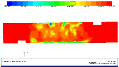
[image:4.612.314.521.256.373.2]4.1 Analysis of oxygen distribution results Through the body sitting height of 1.3 m and standing height of 1.8 m, the cloud drawing of oxygen concentration of the process of air pressure and oxygen supply of the refuge chamber is drawn separately; meanwhile laws shall be summed up through the values of the axis wire in two-plane length directions as well as oxygen-concentration scattered points in the axis wire in the direction of the height of the refuge chamber.
Figure 4Air Pressure And Oxygen Supply Y=1.3 M Oxygen Concentration Cloud Drawing
Figure 5 Air Pressure And Oxygen Supply Y=1.3m Oxygen-Concentration Scattered Points
[image:4.612.87.526.398.734.2]209
Figure 7 Air Pressure And Oxygen Supply Y=1.8m Drawing Of The Oxygen Concentration Scattered Points
Figure 8 Drawing On The Oxygen-Concentration Scattered Points On The Vertical Line In The Air
Pressure And Oxygen Supply System
Through what is shown in Figure 4-8, in the height of 1.3 m, the oxygen concentration in the central positions of the chamber is between 18.0%~21.0%, and the concentration of both sides is between 20.5%~21%; in the height of 1.8 m, the oxygen concentration in the central position of the chamber is between 20.5%~21.0%, and the concentration on both sides is between 20.8%~21.0%. From the above data, we can learn that the oxygen concentration of both sides of the chamber is greater than that of the central position, and the oxygen concentration at the height of 1.8 m is just above 1.3 m. In the perpendicular bisector in the direction of the height, the oxygen concentration of the air is about 19.9%.
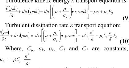
4.2 Analysis of CO2 distribution results The co2 cloud drawing is analyzed through the body sitting height of 1.3 m; meanwhile laws shall be summed up through the values of the axis wire in this plane length directions as well as co2 -concentration scattered points in the axis wire in the direction of the height of the refuge chamber.
Figure 9 Air Pressure And Oxygen Supply Y=1.3m Co2
Cloud Drawing
Figure 10 Air Pressure And Oxygen Supply Y=1.3m And The Drawing On The Co2-Concentration Scattered
Points In The Perpendicular Bisector
Through what is shown in Figure 9-10, at the height of 1.3 m, the co2 concentration of the central positions of the chamber is between 0.209%~0.421%, and the concentration of both sides is between 0.380%~0.420%. At the perpendicular bisector in the direction of the height, the concentration of co2 is about 0.90%.
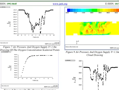
4.3 The control verification with the on-site test
The on-site manned test for the refuge chamber is conducted in the Kong Zhuang Mine, which is a comprehensive inspection on various functional indictors of the chamber.
[image:5.612.314.519.271.450.2]210 O2 concentration is between 19.9%~20.7%, the average value is 20.4%, and its trend of change is as shown in the following drawing.
19.6 19.8 20.0 20.2 20.4 20.6 20.8 21.0
0 240 480 720
Time/min
O
2
Concent
ration/
[image:6.612.91.299.125.469.2]%
Figure 11 The Drawing Of O2 Concentration Change
Curve
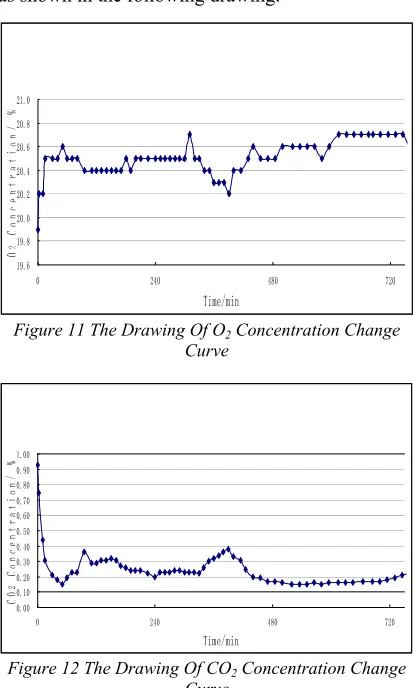
0.00 0.10 0.20 0.30 0.40 0.50 0.60 0.70 0.80 0.90 1.00
0 240 480 720
Time/min
CO
2
C
onc
ent
rat
ion
/
%
Figure 12 The Drawing Of CO2 Concentration Change
Curve
The boundary conditions for various working conditions and numerical simulation in the manned test are similar, and the height of the measuring point is about 1.8, therefore a control analysis is conducted on the average oxygen value result and air pressure and oxygen supply 1.8 m simulation plane cloud drawing.
According to the control results, it is learnt that the simulation result and test result of O2 and CO2 concentration are similar, the reliability of the air pressure and oxygen supply system can be verified
5. CONCLUSIONS
1) The oxygen concentration of both sides of the chamber is higher than that of the central position, and the concentration increases with the increase of the height.
2) The volume of air pressure and oxygen supply in the survival area is 21600L/min, which
can ensure the supply of oxygen in the chamber under manned conditions, providing life guarantee for the persons in distress.
3) The diffused air supply is employed, with an air arrangement spacing of 2.5 m, which ensures the uniform distribution of air in the chamber, and forming turbulent disturbance.
In different types of refuge chambers, the boundary conditions should be regulated based on actual site situation, and the on-site construction and equipment arrangement scheme is optimized, so as to ensure reliability of the confined space. By this way, it can gain the precious time for coalmine underground rescue to safeguard miners’ life safety.
REFRENCES:
[1] Y. Tana, M. Sata, “Asymmetric fingerprinting based on 1-out-of-n oblivious transfer”, Proceedings of International Conference on Computer Application in multimedia, IEEE Conference Publishing Services, February 25-28, 2010, pp. 622-632.
[2] Defa Hu and Qiaoliang Li, “Asymmetric fingerprinting based on 1-out-of-n oblivious transfer”, IEEE Communications Letters, Vol. 14, No. 5, 2010, pp. 101-111.
[1] Li Fangwei, Jin L, Huang Z, Zhang X, “Establishment of Understand emergency System in Xu Zhuang Coalmine of Datun”, Journal of Liaoning Technical University (Natural Science), Vol. 31, No. 2 2012, pp. 189-192.
[2] Li J, Jin L, Wang S, “Research of Mine Safety Protection System Based on Emergency Refuge Space”. China Safety Science Journal, Vol. 20, No. 4, 2010, pp. 155-159.
[3] Michael. A. Fasouletos, “Parametric Design of a Coal Mine Refuge Chamber”, West Virginia University, 2007, pp. 12-50.
[4]A. A, Karim, P.F. Nolan, “Modeling reacting localized air pollution using Computational Fluid Dynamics (CFD)”, Atmospheric Environment. Vol. 45, 2011, pp.889-895.
[5] FlakeK.K,H. W. TAN, “CFD applications in air conditioning design [A]”, Press of China Building Industry, 1999, pp. 1-16.
[6] A. J. Baker Richard, M. Kelso. “Computational fuild Dynamics: A Two-Edged Sword .
211 [7] Chen H, Huang S, Zhang D, “Numerical
Simulation of Air Distribution in Air-conditioned Train Passenger Compartment”, Fluid Machinery, Vol. 40, No. 4, 2002, pp.59-61.
[8] Wang P. Research on the Air Pressure and Oxygen Supply System of the Permanent Refuge Chamber in Changcun Mine, Beijing: Department of Civil & Environmental Engineering of University of Science & Technology Beijing, 2011. pp.15-61.