R E S E A R C H
Open Access
Bit-depth scalable lossless coding for high
dynamic range images
Masahiro Iwahashi
1*, Taichi Yoshida
1, Norrima Binti Mokhtar
2and Hitoshi Kiya
3Abstract
In this paper, we propose a bit-depth scalable lossless coding method for high dynamic range (HDR) images based on a reversible logarithmic mapping. HDR images are generally expressed as floating-point data, such as in the OpenEXR or RGBE formats. Our bit-depth scalable coding approach outputs base layer data and enhancement layer data. It can reconstruct the low dynamic range (LDR) image from the base layer data and reconstructs the HDR image by adding the enhancement layer data. Most previous two-layer methods have focused on the lossy coding of HDR images. Unfortunately, the extension of previous lossy methods to lossless coding does not significantly compress the enhancement layer data. This is because the bit depth becomes very large, especially for HDR images in floating-point data format. To tackle this problem, we apply a reversible logarithmic mapping to the input HDR data. Moreover, we introduce a format conversion to avoid any degradation in the quality of the reconstructed LDR image. The proposed method is effective for both OpenEXR and RGBE formats. Through a series of experiments, we confirm that the proposed method decreases the volume of compressed data while maintaining the visual quality of the reconstructed LDR images.
Keywords: High dynamic range imaging; Lossless coding; Bit-depth scalable coding
1 Introduction
Image data compression technologies, such as the JPEG 2000 international standard [1,2], allow high quality images to be transmitted via worldwide digital commu-nication networks. Digital cinema and 4K images are remarkable examples of such technology [3,4]. These images require a huge number of pixels to express fine textures at high spatial resolutions.
Recently, high dynamic range (HDR) images have attracted considerable attention [5]. These images have a high resolution of pixel values, i.e., numerous pixel tones. Compared with the current standard for low dynamic range (LDR) images, which are expressed in 8 bits, HDR images have an extremely long bit depth and high dynamic range of pixel values. To fully utilize this dynamic range under limited memory space, the pixel values are expressed as floating-point data, such as in OpenEXR or RGBE format [6,7]. This paper focuses on the compres-sion of HDR images in these data formats. Moreover, the
*Correspondence: [email protected]
1Department of Electrical, Electronics and Information Engineering, Nagaoka University of Technology, 1603-1 Kamitomioka, Nagaoka, Niigata, Japan Full list of author information is available at the end of the article
proposed method, referred to as bit-depth scalable coding, is backward compatible with a standard coding method for LDR images.
Bit-depth scalable coding outputs compressed data in two layers, a base layer and an enhancement layer. From the bit stream in the base layer, the LDR image is decoded with a standard lossy decoder. By adding the bit stream in the enhancement layer, the original HDR image can be decoded without any loss. This scalable coding system has the advantage that it can directly accommodate both HDR and LDR users. Therefore, the system has attracted many researchers, and a number of variations have been reported [8-15].
Ward et al. [8] proposed a backward compatible bit-depth scalable coding method in which the original HDR color image is tone mapped in the base layer to produce an LDR image that is compressed by the JPEG inter-national standard encoder. The enhancement layer then embeds the luminance ratio of the LDR and HDR images. The original HDR color image is decoded by multiply-ing the luminance ratio in the enhancement layer and the LDR color image in the base layer. This method has been extended to video signals and has attracted attention as
a bit-depth scalable video coding method in international standardization activities [9-11,16]. For still images, Khan introduced a piecewise linear model of a tone mapping [12]. Jinno et al. improved the coding efficiency in the enhancement layer by replacing the ratio with a low-pass-filtered HDR image [15]. However, these reports focused on ‘lossy’ coding for HDR images.
Unlike these previous reports, we discuss the ‘lossless’ coding of HDR images under a scalable coding scheme that is compatible with lossy LDR image coding. The loss-less coding of HDR images is especially important for storing and archiving original visual data such as med-ical, artistic, and astrograph images. Such data can be used for diagnosis based on medical images, analysis of astrograph images, art preservation, and bio-medical detections [17,18].
First, we discuss a baseline method [19] that was sim-ply extended to lossless scalable coding from a non-scalable HDR image coding method [20]. Although the baseline method is straightforward and easy to imple-ment, the coding efficiency in the enhancement layer is not satisfactory. To cope with this problem, we intro-duced a reversible logarithmic mapping and reintro-duced the dynamic range of the HDR images [19,21]. This approach was shown to be effective for compressing data in the enhancement layer. However, the method was limited to the OpenEXR format [6]. Another rep-resentative format, referred to as RGBE [7], has been ignored.
In this paper, we improve on our previous conference papers [19,21] and add some theoretical analysis. First, we show that a simple extension of the reversible loga-rithmic mapping (Rev) to the RGBE format degrades the visual quality of the decoded LDR images. To avoid this problem, we introduce a format conversion (Cnv) to the system. We demonstrate that simply extending Rev mag-nifies the quantization error added by the lossy coding in the base layer. Second, we analyze the theoretical basis for why our method improves the coding efficiency of the sys-tem. We estimate how the bit depth of the residual image to be encoded in the enhancement layer is reduced by Rev. We also explain why the simply extended Rev degrades the LDR images, and why Cnv improves their quality in the RGBE format.
This paper is organized as follows. In Section 2, we describe two floating-point data formats and a non-scalable HDR image coding method. A baseline non-scalable coding method that simply extends the non-scalable cod-ing approach is then summarized in Section 3, and the concept and implementation of the proposed method are introduced in Section 4. The theoretical analysis is described in Section 5, and our experimental results are summarized in Section 6. Finally, we present our conclu-sions in Section 7.
2 Data format and non-scalable coding
We first describe two floating-point data formats for HDR images. A non-scalable lossy coding method, which is extended to scalable lossless coding of HDR images in the next section, is also summarized.
2.1 Type A format of HDR images
To date, there are two well-known representative data for-mats for HDR images. One is the OpenEXR floating-point data format [6] and the other is the RGBE data format [7]. In the OpenEXR data format, a pixel value xH,c of an HDR image is described by an exponent value xE,c, mantissa valuexM,c, and sign valuexS,cas
xH,c=(−1)xS,c
1+2−10xM,c
2−15+xE,c
if xE,c=0 (1)
and
xH,c=(−1)xS,c
0+2−10xM,c
2−14
if xE,c=0 (2)
for a color componentc∈ {R,G,B}. The exponent, man-tissa, and sign values are given as integers in the ranges
xM,c∈
0, 210−1, xE,c∈
0, 25−1, xS,c∈[0, 1] . (3)
The mantissa, exponent, and sign have depths of 10 bits, 5 bits, and 1 bit, respectively. Therefore, a pixel value of an HDR image is expressed in 10+5+1 = 16 bits for each color component. Note that in certain special cases, xE,c=31 [6].
In the remainder of this paper, we denote the exponent, mantissa, and sign of each color component as a vector
⎧ ⎪ ⎨ ⎪ ⎩
xE =xE,R, xE,G, xE,BT xM =
xM,R, xM,G, xM,B T
xS =
xS,R, xS,G, xS,B T
(4)
and define the HDR image dataxDas
xD=[xE, xM, xS] . (5)
Using these vectors, we denote Equations 1 and 2 as
xH =FltA(xD), (6)
where the pixel value of the HDR imagexHis
xH =
xH,R, xH,G, xH,B T
. (7)
Hereafter, we refer to OpenEXR as the ‘type A’ format.
2.2 Type B format of HDR images
In the RGBE data format, a pixel value of an HDR image xH,cis given as
xH,c=
xM,c+0.5
256 2xE,0−128 ifxE,0=0
for a color componentc∈ {R,G,B}. Both the mantissa and exponent have depths of 8 bits, i.e.,
xM,c∈
0, 28−1, xE,0∈
0, 28−1. (9)
The exponentxE,0is commonly used among three color components. In this format, a pixel value is expressed with a total of 32 bits [7]. Using the vectors, we denote Equation 8 as
xH =FltB(xD). (10)
Hereafter, we refer to RGBE as the ‘type B’ format. Note that, for a type B image,xHin Equation 10 is non-negative. In contrast,xH in Equation 6 for a type A image can be negative, zero, or positive.
[image:3.595.60.541.586.712.2]2.3 Non-scalable lossy coding
Figure 1 illustrates the ‘HDR image coding in JPEG 2000’ reported in [20]. At the encoder, the HDR image data xD is converted into the pixel valuexH by Flt, where Flt denotes FltA in Equation 6 for type A images and FltB in Equation 10 for type B images. The logarithmic func-tion logeis applied to each color component ofxH. Note that pixel values that are less than or equal to zero are first clipped to the minimum positive pixel value in the image. In terms of the signal-to-noise ratio (SNR) of the variances, the effect on the LDR images is almost zero. At worst, of the nine test images considered in this paper, the SNR is less than 10−2[%] for a type A ‘still life’ image. The effect on HDR images is also limited, with an SNR of less than 10−10[%] for the same input image.
The pixel values are normalized to the range [0, 255] by
Nrm(x)=(x−minX)· 255
maxX−minX (11)
forX = {x|x ∈ image}, where minX and maxXare the minimum and maximum pixel values in the setX, respec-tively. Because the input values to the encoder must be integers, the results are rounded to be integers. Namely,
xB=Rnd(Nrm(loge(Clp(xH)))) (12)
is fed into the encoder, where Rnd and Clp are the round-ing and clippround-ing operations, respectively. In the decoder, the HDR pixel valuesyHare recovered from the decoded imageyBwith the inverse of each Nrm and loge.
In this paper, we extend this method to the scalable loss-less coding of HDR images. The tone mapping operator Tmo described in Section 2.4 is added to this procedure as ‘part A’ to display color LDR images with better quality.
2.4 Tone mapping operation
We now summarize the tone mapping operator for color images based on the Hill function [5]. A pixel value of the HDR imageyH,cis tone mapped toyL,cof the LDR image as
yL,c=Rnd
255yH,c·yL,Y/yH,Y
(13)
forc∈ {R,G,B}, where
yH,Y =0.27yH,R+0.67yH,G+0.06yH,B yL,Y =Hill
yH,Y/Y¯H,Y
, (14)
and the Hill function is defined as
Hill(x)= x a
xa+ba. (15)
In (14),Y¯H,Yis defined as ¯
YH,Y=exp
Ensloge(yH,Y)
, (16)
where Ens(·)denotes the ensemble average over all pos-itive values of yH,Y in the image. a and b are user-set parameters. In our experiments, we use(a,b)=(1, 1). We denote the tone mapping in Equation 13 as
yL=RndClp’TmoyH, (17)
where
yH =yH,R, yH,G, yH,B T
yL =yL,R, yL,G, yL,B
T (18)
for color components. Because the output values of Tmp exceed 8-bit integers for color images, we clip the output values to the range [0, 255] with Clp’.
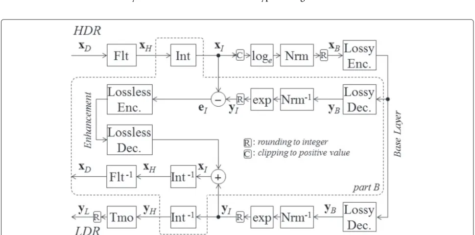
3 Baseline method
The baseline scalable lossless coding method is simply an extension of the non-scalable lossy coding method. We now summarize this baseline method, as well as the problem considered in this paper.
3.1 Scalable lossless coding
Figure 2 illustrates the baseline method, which we use as a reference in this paper. This is a simple extension of the non-scalable lossy coding in Figure 1 to the scalable loss-less coding of HDR images. ‘Part B’ denotes the processes that have been added.
To achieve the lossless coding of HDR images,xHis con-verted into the integer value xI by the reversible integer mapping Int detailed in Section 3.2. Note that the inverse mapping Int−1 reconstructs the original value without any loss. The procedure for generating the LDR images is almost the same as the method in Figure 1. The bit stream needed to reconstruct the LDR image is embedded in the base layer. In the enhancement layer, the integer valueyI is reconstructed from the decoded LDR imageyBwith the inverse normalization Nrm−1, the exponential function exp, and the rounding operation
yI=Rnd
expNrm−1(yB). (19)
Finally, the residual
eI=yI−xI (20)
is encoded with a lossless coding method to generate the bit stream in the enhancement layer.
3.2 Reversible integer mapping
The reversible integer mapping Int from the real valuexH to the integer valuexIwas introduced in [19]. It is defined as
xI,c=
(−1)xS,cx
H,c225−minXE−210
if minXE=0
(−1)xS,cx
H,c224 if minXE=0
(21)
wherec∈ {R,G,B}andXE = {xE,c|xE,c∈image}for type A images. This is a simple scaling applied to the rational numberxH,cin Equation 1 so that it becomes an integer. In other words, we shift the decimal point to the right. Note that the minimum minXEof all the pixel valuesxEin the image is stored and embedded into the bit stream. We denote the mapping in Equation 21 as
xI=IntA(xH) (22)
for
xI=
xI,R, xI,G, xI,B T
. (23)
Similarly, a mapping for type B images can be defined as
xI,c=
256xH,c2128−minX + E −0.5
2+1 (24)
wherec ∈ {R,G,B}andXE+ = xE,c|xE,c>0
. Note that the minimum minXE+of all the positive pixel valuesxE>0 in the image is stored and embedded into the bit stream. We denote this mapping as
xI=IntB(xH) (25)
[image:4.595.55.540.470.710.2]for type B images.
Note that the inverse of this mapping recovers the origi-nal value without any loss. Therefore, the baseline method becomes lossless for the original HDR image.
3.3 Problem setting
In this paper, we tackle the following limitation of the baseline method. As a result of the reversible integer map-ping, the residualeI in Equation 20 requires a very large bit depth. It is somewhat difficult to compress this data volume in the high bit rate coding of the LDR image. This is because eI is a magnified version of the coding noiseeB= yB−xB. In lossy coding, the noiseeBis added in the base layer and is magnified by Nrm−1 and exp as indicated in Equation 19. Because this noise tends to have a weak correlation, the differenceeIalso has a weak correlation. Therefore, the data volume of the enhance-ment layer becomes huge. Note that the correlation ofeI increases in the low bit rate coding of the LDR image. This is investigated in Section 6.
To cope with this problem, we previously introduced the reversible logarithmic mapping (Rev) to reduce the bit depth of the residual image [19]. However, in this previous report, we only presented experimental results without any theoretical endorsement. In this paper, we theoreti-cally compare Int and Rev in respect of the bit depth of the residual image in the enhancement layer.
In addition, Rev has been limited to the type A format, ignoring type B. In this paper, we show that a simple exten-sion of Rev to the type B format degrades the LDR images. To avoid this problem, we introduce a format conversion (Cnv) from type B to type A in the base layer. We present a theoretical justification for why the simply extended Rev degrades the LDR images and Cnv improves its quality for type B images.
4 Proposed method
The reversible logarithmic mapping (Rev) is introduced to reduce the data volume of the enhancement layer. In par-ticular, for type B format images, the format conversion (Cnv) is introduced to maintain the visual quality of the LDR images.
4.1 Type I method for type A format images
Figure 3 illustrates the proposed type I method. Instead of Flt and Int in the baseline method (Figure 2), the reversible logarithmic mapping Rev defined in Section 4.2 is applied to the HDR dataxDto producexR. This is converted to an 8-bit depth integerxBas
xB=Rnd(Nrm(Clp(xR))) (26)
[image:5.595.59.541.421.713.2]and fed into the lossy encoder, which outputs the bit stream in the base layer. The reconstructed pixelyBgiven
by the decoder is inversely normalized and rounded to an integer as
yR=RndNrm−1yB
. (27)
Then, the difference
eR=xR−yR (28)
is encoded with the lossless encoder to generate the bit stream in the enhancement layer. In the decoder, yR is added to eRto recover xR. Applying the inverse of Rev, the original HDR dataxDare retrieved without any loss. Namely, they are recovered as
xD=Rev−1(eR+yR). (29) The LDR image yL is reconstructed from the decoded imageyBin a similar way to the baseline method with a compensation factor (Cmp). This recovers the HDR pixel value yH, and then applies the tone mapping operation Tmo as
yL =RndTmoFltRev−1yR
=RndCmpyR. (30)
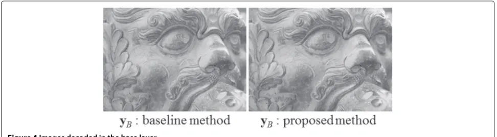
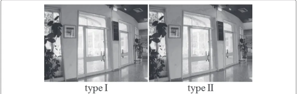
It is also possible to displayyBas an LDR image with-out using Cmp. In this case,yBin the proposed method is almost the same as that of the baseline method as illus-trated in Figure 4. There are two approaches that use the Hill function in Equation 15 to generate the LDR image yLexampled in Figure 5. The first introduces Cmp in the encoding process, and the second introduces Cmp in the decoding process. The former case is convenient for data receivers, because it is not necessary to add Cmp to a stan-dard decoder. However, this increases the data volume of the enhancement layer. In this paper, we employ the latter approach.
4.2 Reversible logarithmic mapping
In the proposed type I method illustrated in Figure 3, the reversible logarithmic mapping is applied to generate the
integer valuexR. This technique was originally introduced in [22]. The mapping for type A images is defined as
xR,c=(−1)xS,cxE,c−minXE210+xM,c (31)
forc∈ {R,G,B}. We denote this mapping as
xR=RevA(xD) (32)
for
xR=
xR,R, xR,G, xR,B T
. (33)
This mapping approximates the logarithm of an HDR imagexH. SubstitutingxE,cfrom Equation 1, i.e.,
xE,c=log2xH,c−log2
1+2−10xM,c
+15, (34)
for positive values in Equation 31, we have
xR,c=
log2xH,c+15−minXE−A
210 (35)
where
A =log2
2−10xM,c+1
−2−10xM,c =log2δA+1
2δA
(36)
forδA=2−10xM,c. As indicated in Equation 35, RevA gen-erates a good approximation of the logarithm of the HDR image [23,24]. The approximation error is relatively small, asAfluctuates around 0.06 depending on the mantissa. Therefore, Nrm(xR)becomes close toxBin Equation 12. This is encoded with a standard lossy encoder to generate the bit stream in the base layer.
[image:6.595.55.541.586.720.2]The reversible logarithmic mapping is suitable for loss-less scalable coding because it one-to-one maps an integer to an integer. Therefore, its inverse mapping reconstructs the original integer values without any loss, i.e., Rev is ‘reversible’. This property also reduces the dynamic range of the mapped integer values. We have experimentally confirmed [21] that the residual in the enhancement layer eR has a lower bit depth than that of eI in the base-line method. We provide the theoretical basis for this observation in Section 5.1.
Figure 5LDR images tone mapped with the Hill function.
4.3 Type I method for type B format images
For type A images, RevA in Equation 32 is applied in Figure 3. For type B images, a direct extension of RevAcan be defined as
xR,c=
x∗E,028+xM,c+1 if xE,0=0
0 if xE,0=0 (37)
forc∈ {R,G,B}and
x∗E,0=xE,0−minXE++1. (38) We denote this mapping as
xR=RevB(xD), (39)
and apply this to type B images in the type I method. Note that the depth ofxRfrom RevBis a maximum of 16 bits for each color component. Therefore, it costs 48 bits for all the color components, which exceeds the original 32-bit data. However, using the reversible color transform
(RCT) in JPEG 2000 lossless coding reduces the cost by 16 bits. The RCT is defined as
⎧ ⎨ ⎩
x1= (xR+2xG+xB) /4 x2=xB−xG
x3=xR−xG
(40)
Because the second and third row of this RCT take the dif-ference between the color components, the exponent term x∗E,0in Equation 37 disappears. As a result, the bit depth becomes 48−16=32 bits in total. Furthermore, the expo-nent term is less than 5 bits in the type B images tested in our experiment. Therefore, in practice, the system can compress the data volume.
[image:7.595.56.541.558.712.2]In this paper, we show that the quality of LDR images is degraded in this directly extended RevBfor type B images. Figure 6 shows some LDR images produced by the pro-posed type I and type II methods. The former has lower quality than the latter, with a peak SNR (PSNR) of 20.79 dB compared with 29.08 dB at the same bit rate of 5.23 bppc in the base layer. The reason for this is analyzed
in Section 5.2. To solve this problem, we introduce the following format conversion.
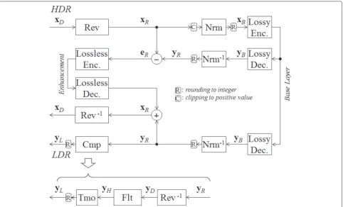
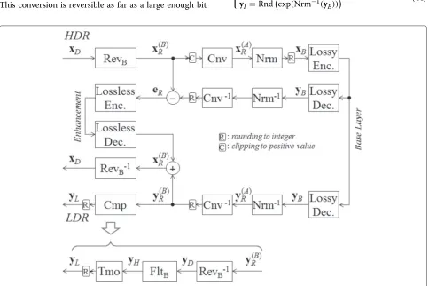
4.4 Type II method for type B format images
Figure 7 illustrates the modified method for type B images. We refer to this as the type II method. The type II approach includes the format conversion (Cnv). First, RevB converts the HDR data xD into type B xR. In the figure, this is denoted as x(RB) to clearly indicate the type. The conversion introduced in this paper is defined as
⎧ ⎨ ⎩
Cnv(x)=RevA
Flt−A1
FltB
Rev−B1(x)
x=Clpx(RB)
(41)
as illustrated in Figure 8. In the proposed type II method,
xB=Rnd
NrmCnvClpx(RB) (42)
is encoded with the lossy encoder.
As a result of this conversion, the type B image is tem-porarily converted into a type A image in the base layer. Therefore, the problem caused by RevBcan be avoided, and the quality of the LDR image is improved compared to that given by applying the type I method to type B images. This assertion is theoretically endorsed in Section 5.2. This conversion is reversible as far as a large enough bit
depth is assigned to values inside the process. However, reversion is not always necessary, as the system becomes lossless for HDR images in as much as theyRare exactly the same in the encoder and the decoder, even though Cnv is not perfectly reversible.
5 Theoretical analysis
We now present a theoretical analysis of why the proposed method reduces the bit depth of the enhancement layer. The rationale for introducing the format conversion is also explained.
5.1 Bit depth of the enhancement layer
We estimate the bit depth of the residualeIin the baseline method andeRin the proposed method and theoretically demonstrate that the bit depth of the proposed method is smaller than that of the baseline method.
The bit depth of pixel values in an imagexis defined as
Bdp(x)=log2(maxX−minX+1), (43)
where maxX and minX denote the maximum and min-imum pixel values in the image. We must calculate the maximum ofeIin the baseline method to estimate its bit depth. In Figure 2, the relations
xB=Rnd
NrmlogeClp(xI)
yI=Rndexp(Nrm−1(y B))
[image:8.595.57.541.394.716.2](44)
Figure 8The format conversion Cnv in the proposed type II method.
are modeled as
xB=Nrm(logexI)+e1
yI =exp(Nrm−1(yB))+e2
(45)
for positive values of xI, where e1,e2 ∈[−0.5, 0.5] are rounding errors due to Rnd in Equation 44. Therefore, the maximum of
eI=yI−xI
=expNrm−1yB−xI+e2 =expNrm−1(xB+eB)
−xI+e2 =expNrm−1NrmlogexI
+ eB+e1))−xI+e2
(46)
is estimated as
maxEI=maxEB·maxXI·C/255 (47)
for
C=loge(maxXI)−loge
minXI+, (48)
as detailed in Appendix A. Substituting
minEI= −maxEI (49)
and Equation 47 into Equation 43, the bit depth ofeI is estimated as
Bdp(eI) =log2(2·maxEI+1)
≈log2(maxEB·maxXI·C/255)+1, (50) giving the bit depth of the residual of the baseline method. Similarly, using the model
xB =Nrm’(xR)+e1
yR =Nrm’−1(yB)+e2 (51) in the proposed method, the maximum of
eR=yR−xR
=Nrm’−1(xB+eB)−xR+e2 =Nrm’−1Nrm’(xR)+eB+e1
−xR+e2
(52)
is given as
maxER=maxEB·maxXR/255, (53)
as shown in Appendix B. Substituting
minER= −maxER. (54)
and Equation 53 into Equation 43, the bit depth ofeRcan be estimated as
Bdp(eR) =log2(2·maxER+1)
≈log2(maxEB·maxXR) /255)+1, (55) giving the bit depth of the residual of the proposed method.
We can now compareeI andeRin terms of bit depth. The error in the base layereBis composed of errors due to the rounding before applying the lossy encoder, as well as quantization errors added by the lossy coding. Therefore, the maximum and minimum of
eB=yB−xB (56)
are
maxEB= −minEB=Q, (57)
where Qis determined by the quantization step size of the lossy coding in the base layer. Taking the difference between Equation 50 and Equation 55, we have
Bdp=Bdp(eI)−Bdp(eR)
=log2(maxEB·maxXI/255·C) −log2(maxEB·maxXR/255),
(58)
and therefore
Bdp=log2
maxXI·C maxXR
(59)
is the difference in bit depth. From Equations 1, 21, and 31, the maxima ofxIandxRare expressed as
maxXI =
2C∗−1
210≈2C∗·210 maxXR=C∗·210
(60)
for
C∗=maxXE−minXE+γ, (61) whereγ ∈[0, 1)is determined according to the mantissa ∈ 0, 210. Substituting Equation 60 into Equation 59, we have the difference as
Bdp=log2 2C∗·C
C∗ >0, (62)
baseline method. Thus, we have theoretically shown that the proposed method achieves bit-depth reduction in the enhancement layer.
5.2 Difference between type I and type II for type B format Next, we show that the format conversion introduced in Section 4.4 alleviates the degradation of LDR images in the base layer. The output LDR imageyLis tone mapped from the decoded HDR imageyH, which is generated fromyRin the proposed method. Therefore, we analyze the relation betweenyH andyRfor the type I and type II methods.
As illustrated in Figure 3, the proposed type I method producesyHas
yH =FltB
Rev−B1yR. (63)
for type B images. For example, the exponent of the type B image data becomes
x∗E,0=xR,c−xM,c−1
/256 (64)
from the inverse of Equation 37. Substituting this equation into Equation 8, we have
xH,0=fIa(xR,c)·fIb(xM,c)·2minX +
E−127, (65)
where ⎧ ⎪ ⎪ ⎪ ⎪ ⎪ ⎨ ⎪ ⎪ ⎪ ⎪ ⎪ ⎩
fIa(xR,c) = exp(xR,c·2−8loge2), fIb(xM,c) = δB+2
−9
2δB+2−8 ∈[0.002, 0.499] ,
δB = x256M,c ∈[0, 1).
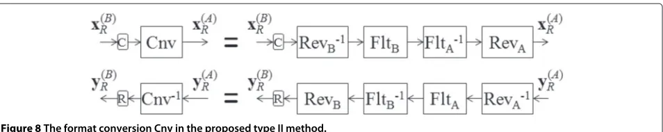
[image:10.595.305.539.545.704.2]This is the relation between xH and xR and includes a function fIa that is proportional to the exponent of xR. However, note that this is chopped by the function fIb. This is confirmed by Figure 9, which indicates the rela-tion betweenxBandxH for the type B ‘tree’ image. Note that xB is a scaled version of xR. The points ‘o’ indicate
Figure 9Mapping in the systems for the type B image ‘tree’.
where the mapping given by the type I method becomes discontinuous.
In contrast, the proposed type II method in Figure 7 producesyHas
yH =FltB
Rev−B1
Rnd
Cnv−1
y(RA)
≈FltA
Rev−A1y(RA) (66)
neglecting the effect of Rnd. This means that the image is converted to type A in the base layer. Therefore, taking the inverse of Equation 35, we have
xH,c=fIIa(xR,c)·fIIb(xM,c)·2minXE−15, (67) where
⎧ ⎪ ⎨ ⎪ ⎩
fIIa(xR,c) = exp(xR,c·2−10loge2), fIIb(xM,c) = δA2δ+A1 ∈[1, 1.06),
δA = 1024xM,c ∈[0, 1).
Similar to the type I method, the functionfIIais propor-tional to the exponent ofxR. Note that the functionfIIbis close to one. Therefore, unlike the type I method, the type II method gives an HDR imagexH that is approximately proportional to the exponent ofxR. This is confirmed by the points marked ‘x’ in Figure 9.
Next, we investigate how the mappings in Equations 65 and 67 magnify the quantization erroreB. Denoting the mapping asxH =f(xB), the error is magnified as
yH−xH = f(xB+eB)−f(xB) (68)
≈ ∂f(xB)
∂xB ·
eB. (69)
Figure 10 illustrates the absolute value of
∂f(xB)
∂xB ≈
yH−xH yB−xB =
xH
xB
(70)
for the type I method (marked ‘o’) and the type II method (marked ‘x’). In the figure, a larger value signifies greater
[image:10.595.56.303.551.713.2]amplification of the error. We can see that the type I method has larger values, especially at the jump points of Figure 10 which come from the discontinuous points of Figure 9. This implies that the degradation in LDR image quality produced by the type I method is alleviated by the type II method, which uses the format conversion in Section 4.4.
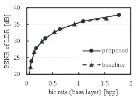
6 Experiments
We now describe a series of experiments that tested nine HDR images, including five type A images and four type B images. For the lossy coding in the base layer and the loss-less coding in the enhancement layer, we used the JPEG 2000 international standard [1] in lossy mode and lossless mode, respectively.
6.1 Base layer
We compared the coding performance in the base layer of the baseline method and the proposed method. In this section, the proposed method denotes the type I pro-cedure in Figure 3 for type A images and the type II procedure in Figure 7 for type B images. Figure 11 com-pares the baseline and proposed methods for the type A ‘cannon’ image. The horizontal axis records the data vol-ume of the base layer in bits per pixel per color component (bppc). The vertical axis indicates the LDR image quality in terms of PSNR, which is defined by
PSNR=10 log10 255
2
Ens(yL−xL)2
[dB] (71)
for
xL=Rnd(Clp’(Tmo(xH))), (72)
[image:11.595.308.541.89.250.2]where Ens(·) denotes the ensemble average over all pix-els in the image. The results indicate that the proposed method is slightly worse (by 0.46 dB at 3.1 bpp) than
Figure 11Coding performance in the base layer for type A image ‘cannon’.
Figure 12Coding performance in the base layer for type B image ‘Belgium’.
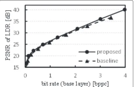
the baseline approach. Figure 12 indicates the rate distor-tion curves for the type B ‘Belgium’ image. The results are very similar to those for ‘cannon’. The ‘tree’ image was investigated in different formats. Figures 13 and 14 indicate the curves for this image in type A and type B for-mats, respectively. Figure 15 summarizes the PSNR at 1.5 bppc in the base layer. This indicates that the proposed method is slightly better than the baseline technique. It can be concluded that the proposed method is compara-ble to or slightly better than the baseline method. This is considered to be because of the similarity ofxB in the baseline method and the proposed method. Both quan-tities represent the logarithm of the original HDR image xH.
[image:11.595.58.294.540.702.2]6.2 Enhancement layer
Figure 16 compares the output from the proposed and baseline methods for the type A ‘cannon’ image. The horizontal axis indicates the PSNR of the reconstructed
[image:11.595.306.542.546.704.2]Figure 14Coding performance in the base layer for type B image ‘tree’.
LDR images, and the vertical axis indicates the bit rate of the bit stream in the enhancement layer. Note that, because the decoded HDR images are lossless, the PSNR is infinite. This figure indicates that the proposed method reduces the bit rate by more than 3.4 bppc for this image. As indicated in the figure, the bit rate in the enhance-ment layer decreases as the PSNR increases. However, the bit rate in the base layer increases with PSNR, which means that there is a trade-off in the bit rate in these layers.
[image:12.595.57.299.90.243.2]Figure 17 shows the results for the type B ‘Belgium’ image. We can observe that the bit rate decreases by 8.03 bppc at 35 dB LDR image quality. Unlike the case in Figure 16, the bit rate increases with the PSNR. This is because the correlation among neighboring pixels in eI increases in low PSNR (low bit rate) coding of the LDR image as indicated in Figure 18. For this input image, the correlation is observed to be 0.14 at a PSNR of 36.9
Figure 15Image quality of LDR images for various images at 1.5 bppc enhancement layer bit stream.
Figure 16Bit rate of the enhancement layer for type A image ‘cannon’.
dB. The correlation monotonically increases as PSNR decreases, reaching 0.80 at 18.8 dB. BecauseeIis encoded with a transform that uses this correlation, a higher cor-relation serves to lower the bit rate. This is why the curve of the baseline method in the figure increases monoton-ically. The bit depth of the enhancement layer decreases monotonically from 26.7 bits at a PSNR of 18.8 dB to 24.1 bits at 36.9 dB as indicated in Figure 19. Furthermore, the logarithm of the variance ofeI is also monotonically decreasing as indicated in Figure 20.
[image:12.595.57.294.526.705.2]The ‘tree’ image was again investigated in different for-mats. Figures 21 and 22 show the bit rate for the type A and type B image formats, respectively. We can see that better PSNR in the LDR images brings about a lower bit rate in the enhancement layer. This suggests that a higher data volume in the base layer will lead to a lower vol-ume in the enhancement layer. Figure 23 summarizes the bit rate at 35 dB LDR image quality. This figure indicates that the proposed method reduces the data volume of type
[image:12.595.306.539.550.702.2]Figure 18Correlation of the difference for type B image ‘Belgium’.
A images by a minimum of 3.82 bppc (for the ‘cannon’ image) and by a maximum of 8.82 bppc (for ‘still life’). For type B images, the data volume is reduced by a min-imum of 7.8 bppc for ‘desk’. It was confirmed that the proposed method significantly reduces the data volume of the enhancement layer for both type A and type B format images.
7 Conclusions
[image:13.595.58.296.90.235.2]In this paper, we have presented a bit-depth scalable loss-less coding for HDR images in floating-point data formats. Unlike most conventional scalable coding methods, the proposed method reconstructs the original HDR image without any loss. Introducing a reversible logarithmic mapping and format conversion technique, it was con-firmed that the proposed method reduces the bit depth as well as the bit rate in the enhancement layer. It was also confirmed that the proposed method maintains the LDR image quality and coding performance of the base-line method in the base layer for both the OpenEXR and RGBE formats.
[image:13.595.304.541.342.706.2]Figure 19Bit depth of the difference for type B image ‘Belgium’.
Figure 20Log of variance of the difference for type B image ‘Belgium’.
As our investigation has been limited to a difference-based approach, it is necessary to include ratio-difference-based approaches, such as [8].
Appendix A Substituting
⎧ ⎨ ⎩
Nrm−1(xB)=xB·C/255+C1 C=C2−C1
C1=loge
minXI+, C2=loge(maxXI) into
eI=expNrm−1NrmlogexI + eB+e1))−xI+e2, we have
eI =exp(x+)−xI+e2
where
x=logexI,
=(eB+e1)·C/255.
[image:13.595.57.292.565.711.2]Figure 22Bit rate of the enhancement layer for type B image ‘tree’.
Whenxtakes its maximum value, xholds. For exam-ple, the value of/xfor all images tested in this paper is less than 10−4. In this case,
eI = exp(x+)−xI+e2 ≈ ∂exp(x)
∂x +exp(x)−xI+e2 holds. Therefore, we have
eI=exp(x)+exp(x)−xI+e2 =explogexI
(eB+e1)·C/255 +explogexI
−xI+e2
=xI(eB+e1)·C/255+xI−xI+e2 =xI(eB+e1)·C/255+e2
namely,
maxEI =maxXI(maxEB+e1)·C/255+e2.
Figure 23Bit rate of the enhancement layer for various images at 35 dB LDR image quality.
According to our experiments, maxEIis 7.23×10³in ‘can-non’ at minimum. Thereforee2is negligible compared to maxEI since the maximum ofe2 is 0.5. Similarly, maxEB takes value between 3 and approximately 27depending on the bit rate of the base layer. Therefore,e1is negligible in low bit rate compared to maxEBand we have
maxEI =maxXI·maxEB·C/255.
Note that precision of this estimation slightly decreases in high bit rate coding in which maxEBtakes small value such as 3.
Appendix B Substituting
⎧ ⎪ ⎪ ⎨ ⎪ ⎪ ⎩
Nrm’−1(xB)=xB·C/255+C1 Nrm’(xR)=
xR−C1
·255/C C=C2−C1
C1 =minXR, C2 =maxXR into
eR=Nrm’−1
Nrm’(xR)+eB+e1
−xR+e2, we have
eR=Nrm’−1
xR−C1
·255/C+eB+e1
−xR+e2, =xR−C1 +
eB+e1
·C/255+C1 −xR+e2,
=eB+e1
·C/255+e2.
According to our experiments, maxER is 94 in ‘cannon’ at minimum. Thereforee2∈[−0.5, 0.5] is negligible com-pared to maxER. Similarly to Appendix A,e1is negligible compared to maxEB. As a result, we have
maxER=maxEB·maxXR/255.
Competing interests
The authors declare that they have no competing interests.
Acknowledgements
This work was supported by JSPS KAKENHI Grant Number 26289117.
Author details
1Department of Electrical, Electronics and Information Engineering, Nagaoka
University of Technology, 1603-1 Kamitomioka, Nagaoka, Niigata, Japan.
2Department of Electrical Engineering, University of Malaya, 50603 Kuala
Lumpur, Malaysia.3Department of Information and Communication Systems,
Faculty of System Design, Tokyo Metropolitan University, 6-6 Asahigaoka, Hino, Tokyo, Japan.
Received: 25 June 2014 Accepted: 19 February 2015
References
1. ISO/IEC 15444-1,Information Technology - JPEG, 2000 Image Coding System, Core coding system, ITU-T Recommendation, T800, (Geneva, 2002), pp. 1–194
[image:14.595.57.291.526.703.2]3. A Descampe, F-O Devaux, G Rouvroy, J Legat, J-J Quisquater, B Macq, A flexible hardware JPEG, 2000 decoder for digital cinema. IEEE Trans. Circuits Syst. Video Technol.16(11), 1397–1410 (2006)
4. K Kaneko, N Ohta, inProc. Int. Conf. Virtual Syst. Multimedia. 4K applications beyond digital cinema (Seoul, 2010), pp. 133–136
5. E Reinhard, G Ward, S Pattanaik, P Debevec,High Dynamic Range Imaging: Acquisition, Display, and Image-Based Lighting. (Morgan Kaufmann, San Francisco, CA, USA, 2010)
6. R Bogart, F Kainz, D Hess,OpenEXR image file format. ACM SIGGRAPH, Sketches & Applications, (San Diego, 2003)
7. G Ward, Real Pixels Graphics Gems II (1991)
8. G Ward, M Simmons, inProc. ACM SIGGRAPH 2006 Courses. JPEG-HDR: a backwards-compatible, high dynamic range extension to JPEG (Boston, 2006)
9. R Mantiuk, A Efremov, K Myszkowski, H-P Seidel, Backward compatible high dynamic range MPEG video compression. ACM Trans. Graph.25(3), 2006
10. M Winken, D Marpe, H Schwarz, T Wiegand, inProc. IEEE Int. Conf. Image Process. Bit-depth scalable video coding, vol. 1 (San Antonio, 2007), pp. 5–8 11. S Park, KR Rao, Bit-depth scalable video coding based on H.264/AVC. IEICE
Trans. Fundamentals.E91-A(6), 1541–1544 (2008)
12. IR Khan, inProc. IEEE Int. Conf. Acoustics Speech Signal Process. Two layer scheme for encoding of high dynamic range images (Las Vegas, 2008), pp. 1169–1172
13. H Kikuchi, W Otake, M Iwahashi, inProc. Int. Symp. Intell. Signal Process. Commun. Syst.Bit rate reduction of enhancement layer in bit-depth scalable coding (Kanazawa, 2009), pp. 264–267
14. A Boschetti, N Adami, R Leonardi, M Okuda, inProc. IEEE Int. Conf. Image Process. Flexible and effective high dynamic range image coding (Hong Kong, 2010), pp. 3145–3148
15. T Jinno, M Okuda, N Adami, inProc. IEEE Int. Conf. Acoustics Speech Signal Process. New local tone mapping and two-layer coding for HDR images (Kyoto, 2012), pp. 765–768
16. J-C Chiang, W-T Kuo, P-H Kao, Bit-depth scalable video coding with new inter-layer prediction. EURASIP J. Adv. Signal Process.2011(1), 1–9 (2011) 17. Y Zhang, DR Bull, E Reinhard, inProc. Int. Conf. Image Process. Perceptually lossless high dynamic range image compression with JPEG, 2000 (Kyoto, 2012), pp. 1057–1060
18. YS Shih, WC Zhang, H Sheng, YH Yang, ST Sun, CC Wu, YC Lee, SS Lee, SC Huang, inProc. Int. Comp. Symp. Bio-inspired JPEG XR CODEC design for lossless HDR biomedical image, (2010), pp. 148–153
19. M Iwahashi, H Kiya, inProc. Asia-Pacific Signal Inf. Process. Association Annual Summit Conf. Efficient lossless bit depth scalable coding for HDR images (Hollywood, 2012), pp. 1–4
20. R Xu, SN Pattanaik, CE Hughes, High-dynamic-range still-image encoding in JPEG 2000. IEEE Comput. Graphics Appl.25(6), 57–64 (2005) 21. CY Ping, M Iwahashi, H Kiya, inProc. Int. Workshop Adv. Image Technol.
Lossless bit depth scalable coding for floating point images (Nagoya, 2013), pp. 169–174
22. JF Blinn, Floating-point tricks. IEEE Comput. Graph. Appl.17(4), 80–84 (1997)
23. M Iwahashi, H Kiya, inProc. Int. Conf. Acoust. Speech Signal Process. Two layer lossless coding of HDR images (Vancouver, 2014), pp. 1340–1344 24. ML Pendu, C Guillemot, D Thoreau, inProc. Int. Conf. Acoust. Speech Signal
Process. Adaptive re-quantization for high dynamic range video compression (Vancouver, 2014), pp. 7367–7371
Submit your manuscript to a
journal and benefi t from:
7 Convenient online submission
7 Rigorous peer review
7 Immediate publication on acceptance
7 Open access: articles freely available online
7 High visibility within the fi eld
7 Retaining the copyright to your article
![Figure 1 illustrates the ‘HDR image coding in JPEG 2000’reported in [20]. At the encoder, the HDR image datadenotes FltxD is converted into the pixel value xH by Flt, where FltA in Equation 6 for type A images and FltBin Equation 10 for type B images](https://thumb-us.123doks.com/thumbv2/123dok_us/8604278.865601/3.595.60.541.586.712/figure-illustrates-reported-datadenotes-converted-equation-fltbin-equation.webp)