A Review of Analysis and Modeling of Grid
Connected Multiple-Pole Multilevel Unity Power
Factor Rectifier with Less Component Counts
Ranjan Kumar Rai1, Umashankar Patel2 1
M.Tech Scholar (Electronics Devices & Power , 2Assistant professor, Electronics)Department of Electrical& Electronics Engineering DIMAT, Raipur (C.G)
Abstract: In this paper, to improve power factor a simple model based on five levels multiple pole is used. It is also used to improve harmonic distortion and efficiency which is done by using reduced number of component counts. Most of the work has been done to obtain these factors. In this project, 5L-M2UPFR is used which give almost unity power factor.By this method, the unity power factor with input current shaping is obtained with less number of measurement components. This paper uses balanced and unbalanced load condition over which these improved response is obtained.
Keywords: Vienna Rectifier, 5L-M2UPFR, Power factor, average current control (ACC), Electrical Grid.
I. INTRODUCTION
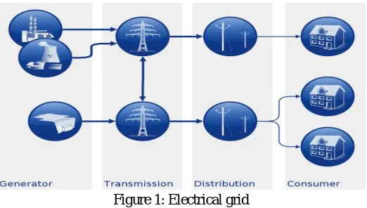
[image:2.612.180.441.401.549.2]Electrical grids consists plants to create electrical power from some form of energy. To hold wires it contains various poles and various towers that are used to transport electricity so that every customer can get it easily. This complete process present in this diagram that how the power generated and transmitted from source to the destination. This is logically grouped into four major groups [1].
Figure 1: Electrical grid
the best source of vulnerabilities. Software and hardware used for building the smart grid infrastructure are liable to being tampered with even before they're linked collectively. Rogue code, including the so-known as common sense bombs which cause sudden malfunctions that may be inserted into software while it's far being advanced. As for hardware, remotely operated “kill switches” and hidden “backdoors” may be written into the chips of computer used by the smart grid and permitting outdoor actors to manipulate the structures. The threat of compromise in the production manner could be very real and is perhaps the least understood hazard. Tampering is sort of impossible to stumble on and even tougher to eliminate. Power stations may be placed near a gasoline supply, at a dam site, or to take advantage of renewable strength assets, and are frequently positioned away from closely populated areas. Multilevel converters have become greater appealing for lots industry and academia research. Most of the commercially to be had multilevel inverters require a bulky section-shifted transformer with multiple bridge rectifiers linked at the front-stop aspect [2,5]. However, the quantity and the load of such configuration are large and heavy. In addition, more losses are skilled in the transformer during low utilization because of its middle resistance [6, 7]. Several new transformers less multilevel rectifier topologies with low switching frequency operation had been reported in the literature. The referred to low-cost topologies have performed accurate performance and additionally confirmed that the clear out length may be extensively reduced in spite of the low switching frequency operation. However, each of those topologies has its limitations and disadvantages. For example, a complex manipulate algorithm is needed to stability the flying capacitors of the three-section megastar-configured PUC topology. While in the case of RPC-DCR topology, simplest two switches are decreased in each phase-leg however the general aspect counts are not notably optimized. Hence, large wide variety of gate drivers and remote gate supplies are still required. Thus, a decrease cost solution is finished with the discount of measurement sensors needed for the remarks manage loop not like the proposed switching method provided in [8]. In addition to that, top notch dynamic reaction is demonstrated with the expected performances of both grid voltage and load modern-day during unbalanced grid condition.
II. OBJECTIVE
The main objective of this work is design a model to obtain improved power factor, with better efficiency and this is done by using less count components that will reduce the total harmonic distortion. In this paper, phase multiple-pole multilevel is used that will also reduce the cost of the effective transformer.
III. PROBLEM STATEMENT
From the analysis of various work has already been done it has been found that there are number of problems associated with these works i.e. the model is bulky because of size of the transformer, the losses of the switching are also dominant which occurs at very high frequency. The effect the output power, power factors, efficiency, total harmonic distortions etc.
IV. MULTIPLE-POLE UNITY POWER FACTOR RECTIFIER TOPOLOGY
A. Basic Operating Principle
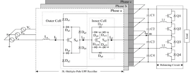
[image:3.612.149.461.596.716.2]A multiple-pole unity power factor rectifier topology with balanced load which is shown in Figure 2 is built on the basis of three-level VIENNA rectifier cells in each phase-leg. The concept of inverter which is similar to multiple-pole structure is used in multilevel diode circuit [9]. Hence, the output terminals of both the circuit, i.e. VIENNA rectifier cells which are linked to the respective dc capacitors with resource of balancing circuit [10, 11]. The overall performance of this method is synthesized which is based on switching state selection and the direction of phase current in which each cell is characterized with the multiple level input voltage stepped waveform.
B. Controller Design
1) Unity Power Factor Control: The load current and grid voltage is controlled by using the power factor control as shown in figure 3. The controller structure is constructed using synchronous reference frame (SRF) current control [12]. To limit the control bandwidth, the complicated phase locked loop design is used in the transformation.
Figure 3: Block diagram of the unity power factor controller with the grid voltage and load current observers.
[image:4.612.180.439.133.239.2]On this basis of the electrical control system there are two types of control is used i.e. voltage and current control. These two control mechanism is applied to both the circuits i.e. at outer loop and at the inner loop. The voltage control carried at the outer loop and current control carried at the inner loop [9]. The dc equivalent capacitor current is calculated by the outer loop control which regulates the output dc link voltage. Meanwhile, the load current is formulated from the power balanced principle.
Figure 4: The Load current observer
C. Voltage Control
The voltage control carried at the outer loop is regulated with a the proportional integral (PI) controller which is expressed as follows
Where,
Kp represents the proportional gain of the dc-link voltage regulator
ti represents the settling time of the dc-link voltage tracking.
The approximated value of the proportional gain (Kp) is obtained from the energy storage model. According to stability criteria, the
proportional gain of the control system expressed in below equation.
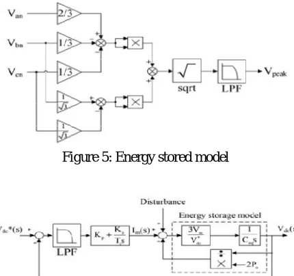
D. Current Control
[image:4.612.204.412.331.394.2]Figure 5: Energy stored model
Figure 6: Peak detector of the grid voltage for the reference sinusoidal wave
E. Grid Voltage
For the proper rectifier configurations various observer strategies had already been proposed [19-21]. Besides these benefit of disposing of the sensors which are needed, this approach reduces the converter size and also offers a lower production cost as well. This simple model will eliminate the problem of 3 levels multiple pole which is total harmonic distortion. To derive and find the ac and dc voltages, the statistics of three phase grid currents are sufficient, but very high dc-link voltage ripples are experienced throughout the computational process. Hence, high cutting edge total harmonic distortion inside the grid is inflicting.
Figure 7: Grid voltage observer
V. CONCLUSION
This proposed topology, i.e. 5 level 5L-M2UPFR method provides very high reliability over the three phase power supply at extreme unbalanced condition of grid. These three conditions will help in the design of the method by which we can obtain the system with reduced number of sensors which improves the failures of the system and by this method almost unity power factor with very less total harmonics distortion (THD) is obtained. Due to less number of sensors, the components count also gets reduced. Most important is that we can design light weight and high power density using this method.
VI. ACKNOWLEDGEMENT
Expression of giving thanks are just a part of those feeling which are too large for words, but shall remain as memories of wonderful people with whom I have got the pleasure of working during the completion of this work. I would like to express my deep and sincere gratitude to my supervisor, Mr. Uma Shankar Patel, Assistant Professor in Department of Electrical & Electronics Engineering, DIMAT, Raipur. His wide knowledge and his logical way of thinking have been of great value for me. His/her understanding, encouraging and personal guidance have provided a good basis for the present work. I am grateful to DIMAT, Raipur (C.G.) which helped me to complete my work by giving encouraging environment.
REFERENCES
[1] United States of America, H.R. 6582: American Energy Manufacturing Technical Corrections Act, 2012.
[2] Kouro, S., Malinowski, M., Gopakumar, K., et al.: ‘Recent advances and industrial applications of multilevel converters’, IEEE Trans. Ind. Electron., 2010, 57, pp. 2553–2580.
[4] http://ec.europa.eu/energy/gas_electricity/smartgrids/taskforce_en.htm.
[5] Miranbeigi, M., Iman-Eini, H., Asoodar, M.: ‘A new switching strategy for transformer-less back-to-back cascaded H-bridge multilevel converter’, IET Power Electron., 2014, 7, pp. 1868–1877.
[6] Daher, S., Schmid, J., Antunes, F.L.M.: ‘Multilevel inverter topologies for stand-alone PV systems’, IEEE Trans. Ind. Electron., 2008, 55, pp. 2703–2712. [7] Steimer, P.K., Winkelnkemper, M.: ‘Transformerless multi-level converter based medium voltage drives’. 2011 IEEE Energy Conversion Congress and
Exposition (ECCE), 2011, pp. 3435–3441.
[8] Gabriel, O.H.P., Maswood, A.I., Ziyou, L., et al.: ‘Input current shaping of five-level multiple-pole VIENNA rectifier topologies with reduced component and better performance’. Presented at the 39th Annual Conf. of the IEEE Industrial Electronics Society, IECON 2013–, 2013.
[9] Ooi, G.H.P., Maswood, A.I., Ziyou, L.: ‘Five-level multiple-pole PWM AC-AC converters with reduced components count’, IEEE Trans. Ind. Electron., 2015, 62, pp. 4739–4748.
[10] Hatti, N., Kondo, Y., Akagi, H.: ‘Five-level diode-clamped PWM converters connected back-to-back for motor drives’, IEEE Trans. Ind. Appl., 2008, 44, pp. 1268–1276.
[11] Ajami, A., Shokri, H., Mokhberdoran, A.: ‘Parallel switch-based chopper circuit for DC capacitor voltage balancing in diode-clamped multilevel inverter’, IET Power Electron., 2014, 7, pp. 503–514.
[12] Maswood, A.I., Fangrui, L.: ‘A unity-power-factor converter using the synchronous reference-frame-based hysteresis current control’, IEEE Trans. Ind. Appl., 2007, 43, pp. 593–599.
[13] Barbi, I., Batista, F.A.B.: ‘Space vector modulation for two-level unidirectional PWM rectifiers’, IEEE Trans. Power Electron., 2010, 25, pp. 178–187. [14] Raj, P.H., Maswood, A.I., Ooi, G.H.P., et al.: ‘Voltage balancing technique in a space vector modulated 5-level multiple-pole multilevel diode clamped
inverter’, IET Power Electron., 2015, 8, pp. 1263–1272.
[15] Maswood, A.I., Al-Ammar, E., Liu, F.: ‘Average and hysteresis current-controlled three-phase three-level unity power factor rectifier operation and performance’, IET Power Electron., 2011, 4, pp. 752–758.
[16] Fangrui, L., Maswood, A.I.: ‘A novel variable hysteresis band current control of three-phase three-level unity PF rectifier with constant switching frequency’, IEEE Trans. Power Electron., 2006, 21, pp. 1727–1734.
[17] Jong-Won, S., Bo-Hyung, C.: ‘Digitally implemented average current-mode control in discontinuous conduction mode PFC rectifier’, IEEE Trans. Power Electron., 2012, 27, pp. 3363–3373.
[18] Ide, P., Froehleke, N., Grotstollen, H.: ‘Investigation of low cost control schemes for a selected 3-level switched mode rectifier’. Nineteenth Int. Telecommunications Energy Conf., 1997. INTELEC 97, 1997, pp. 413–418.
[19] Ohnuki, T., Miyashita, O., Lataire, P., et al.: ‘Control of a three-phase PWM rectifier using estimated AC-side and DC-side voltages’, IEEE Trans. Power Electron., 1999, 14, pp. 222–226.
![figure 3. The controller structure is constructed using synchronous reference frame (SRF) current control [12]](https://thumb-us.123doks.com/thumbv2/123dok_us/8298060.853522/4.612.204.412.331.394/figure-controller-structure-constructed-synchronous-reference-current-control.webp)