Simulation of Microcontroller Based Induction
Motor Drive for Sensorless Approach
Alka Nimbhorkar1, Manisha Dubey2,
1
PhD scholar, 2Professor, Department of Electrical Engg, Maulana Azad National Institute of Technology, Bhopal, Madhya Pradesh, India
Abstract: Proteus based simulation, design and configuration of PIC18F4431 microcontroller for sensorless, open loop Variable Frequency drive speed Control of an AC Induction Motors. Many industrial drives, typically for fan or pump applications, have typically constant speed requirements and hence the induction machine is ideally suited for these. However, the induction machine especially the squirrel cage types quite rugged and has a simple construction. Therefore it is good for variable speed applications if it can be achieved.
The main objective of this paper is to develop an economical controller to control the speed of the induction motor, employing the scalar control model. The voltage and frequency input to the induction motor are to be controlled in order to obtain the desired speed response
Keywords: Motor control, speed control, motor drive, PIC18F4431, microcontroller, soft computing, Artificial intelligence, rotating machineries. Electrical, Power Electronics.
I.
INTRODUCTION
To control of a 3-phase AC induction motor requires pulse-width modulated control of the six switches of a 3-phase inverter bridge connected to the 3 legs of the motor’s windings. The six switches form 3 pairs of “half-bridges”, which can be used to connect each leg to the positive or the negative high-voltage DC bus. As can be seen from the figure, two switches on the same “half-bridge” must never be on simultaneously, otherwise the positive and negative buses will be shorted together. When one switch is on, the other must be off; thus they are driven as complementary pairs. It should also be noted that the switching devices used in the half-bridge (in this case, IGBT’s) often require more time to turn off than to turn on. For this reason, a minimum dead-time must be inserted between the off and on time of complimentary channels.
The PCPWM is well-suited for this application because it can provide up to four pairs of complimentary outputs with programmable dead-time. To drive the AC induction motor, the duty cycles of the PWM outputs to the 3-phase bridge are modulated to synthesize sinusoidal waveforms (three-phase AC) across the 3 motor windings, as depicted in this slide.
When 3-phase AC is applied to the three stator windings (sinusoidal currents, equal in amplitude and frequency, but offset from each other by 120 degrees) the current in the stator windings generates a rotating magnetic field (shown here as the rotating vectors on the x-axis.)
This rotating field induces electromotive force in the rotor, which in turn produces a magnetic field in the rotor that attempts to align with the rotating magnetic field in the stator. This causes the rotor to rotate. See the ap notes listed in the resource section at the end of this presentation, for a more detailed discussion of motor construction which makes this happen.
II. RELATED WORK
It is observed that recently in Traction system DC motor is replaced by the 3-phase squirrel cage induction motor. Recently in Indian railways DC Motor is replaced by Induction Motor, for that it is necessary to apply it with a three phase variable voltage variable frequency (VVVF) inverter and four quadrant converter, whose controls are quite complicated, which is possible only by use of GTOs and microprocessor based control system.
IM has no brushes in armature as its squirrel cage type, less wear and tear as no brushes needed. Robust, cheaper to build and Technically feasible. Power to weight ratio of induction motor is much higher than the DC motor.Its 80186/16-bit MICAS S2 Microprocessor based control which is costlier.
Here required hall effect type speed sensor for speed feedback.
III. PROPOSED SENSORLESS MODULE
So, for sensorless approach, the proposed work in which, 50 Hz AC supply given as input to “3 Phase Rectifier” and the output DC filtered by RC circuit and fed as input to “3 Phase Inverter circuit” as shown in Fig.1. Inverter controlled 3-phase AC a s output to IM for controlled speed, by obtaining controlled gate pulse from “Microcontroller” via “optical fiber” followed by “gate driver”. For that “Microcontroller received input parameters i.e. Ir, Iy, Vr, Vy, Vb by “Hall effect current sensor”& “voltage attenuation”. Microcontroller includes FL (based speed control) & NN (Speed feedback from rotor based on Back-propagation control). The Speed can control by User (by giving command like start, stop, increase Speed, decrease
speed etc. from Monitor, which connected to Microcontroller by RS 232 connector & converter.
Figure1. Proposed Drive System
IV. MICROCONTROLLER OVERVIEW
Processor 18F4431 Features: It is heart of the system. Logical choice for PIC 18F4431 chip selection due to many high-performance, power
Control, motor control applications, and Special
Figure2. Processor 18F4431 pin out
Peripherals with include the following features:
A. 14-Bit Resolution Power Control PWM module
B. (PCPWM) with Programmable Dead-Time Insertion
C. Motion Feedback Module (MFM), including a 3-Channel Input Capture (IC) module
D. Quadrature Encoder Interface (QEI),High-Speed 10-Bit A/D Converter (HSADC)
E. Power Control PWM Module (8 channels), 200Ksps ADC Module,
F. 8MHz Internal Oscillator,40 MHz Max Speed ,USART
V. PROTEUS SIMULATION OF PIC18F4431
Proteus8 based simulation: Uses VSIM for PIC 18f4431 modeling; Operation simulated
A. Key controls for start Stop motor
B. LED indicators for RUN/Stop activity
C. Fault simulation inputs by means of switches
Figure3. Proteus Simulated circuit of PIC18F4431
D. PWM generation for three phases
E. Low pass filtering of PWM using RC circuit giving Sine wave.
F. Frequency variation from 1Hz to 50Hz
G. Using 200 Samples per cycle giving FPWM ranging from 0 Hz to 10Khz
H. It is best simulation software for microcontroller based designs.Popular because of availability of almost all microcontrollers.
I. Allows for testing programs by means of hex file loading
J. GUI for indicating signals as well as peripherals like LCD
K. Logging support for debugging
L. Mapping of microcontroller peripherals to physical ports of PC it is supported by Schematic editor with parts library
M. PCB software with exhaustive footprint library and Complete EDA system.
VI. PARTS DESCRIPTION OF MICROCONTROLLER
PIC18F4431 is the heart of the system, it is driven by a 20Mhz crystal and RC circuit used
as Power ON reset circuit. The PIC 18F4431 is a microcontroller. It software performs the tasks of Speed Control, Fuzzy Logic and Neural Network computations apart form handling the keyboard and LED indications. The basic clock used for the Microcontroller is the Crystal of 20Mhz. A power indicator is provided to inform if the power is present or not to the Processing unit. A RC reset circuit is formed by the use of the Cap which is parallel by a Reset switch S4. When power is turned on or the switch is pressed (manually) the capacitor is in discharged state and causes the MCLR signal to go low causing the processor to reset.
Figure5. Keyboard and LED Circuit
The Microcontroller is provided with three keys: S1 S2 and s3 as shown also three LED indicators apart form the power on indicator are provided.
A. Keyboard Circuit
Each key output is pulled up of 4.7K and
current limiting series resistor of 4.7K. On Key press port line is set to logic 0. Port lines used PORT D5-7. Three keys for User inputs
1) RUN (S1) – Run /Stop Motor
2) INCR (S2) – Increment Set Spee
3) DECR (s3) – Decrement Set Speed
The above mentioned three keys provide for the purpose are that the user can use s1 to Start /Stop the motor, The S2 key can be used by the User to increment the set speed of the motor. The S3 key can be used by the user to decrement the set speed of the motor.
B. LED Indicators
Three LED indicators are operated in sinking mode, which means that the Anode is connected to supply through a resistor which limits current in the LED when it is on and the port pin is connected to the LED cathode. When the pin is made low the LED turns ON.Three indicators connected to port D0-3. Current limiting series resistor of 330 ohms are used and all LEDs are operated in sinking mode.
1) Ready (D1)– System ready for user input
2) Run (D2) – Motor Running
VII. PWM DRIVE AND FAULT DETECT CIRCUIT
Figure6. PWM Drive Circuit: A. PWM drive circuit
There are 6 PWM drive outputs. Provision for hardware filtering to see drive signal. PWM upper switch drive signals (3) are provided to Scope1. Scope 2 is used to monitor Sine wave at RC output.
Similarly, Low pass filtering of PWM using RC circuit giving Sine wave. R =1 K and c =10uf is used. Low pass filtering of PWM waveform to recover sine wave
The Microcontroller Provides 6 PWM drive signals.These signals are available as PWM 0 – PWM5 on Port Rb0 to RB5. The connector Jp4 makes these signals available to the driver circuits which drive the base drive of IGBT of inverter The horizontal connectors above jumpers which are normally not plugged in. When plugged in these two set of three jumpers allow the user to see the Demodulated SVPWM signal on PWM0,1,2 or PWM3,4,5 on the JP6 connector for observation on CRO. This is basically useful for trouble shooting. In normal operation case these jumpers will be unpopulated.
Figure7. Fault Detect Circuit
B. Fault detect circuit
Its feed back three signals from the Motor section to microcontroller 1) Fault – Indicates a Fault i.e. DC over current detected
2) Ready – Indicates ready/ Power supply OK for all modules
3) Shutdown - indicates a shutdown input for emergency
The Ready signal on the other had informs the microcontroller that the power to the Drive electronics is working ok, as without the Drive electronics being powered up there is no point in triggering the IGBTs.When any of these signals are not active the Microcontroller program senses it as a situation where it is unsafe to run the motor further and stops the PWM generation process.
VIII. RS-232 AND SENSOR INTERFACE CIRCUIT
Two signals for communication TX and RX A. MAX232 is used for TTL to RS232 signal
Figure8. RS232 Interface Circuit level inter-conversion
B. MAX232 uses four capacitors for achieving high voltages.
[image:7.612.199.409.428.524.2]In order to communicate with the PC the microcontroller uses its serial port.Port C RC6 is the TX pin and RC7 is the RX pin. The Microcontroller operates on TTL logic levels but thePC serial port operates on signals with RS232 logic levels. A TTL logic 0 is 0v to 0.8 volts and logic 1 is 2.4 v to 5 Volts But with Rs232 levels the logic 0 is a voltage from +3 to +10V to 12V ( 10 or 12 as per power supply of the RS232) And Logic 1 is a voltage from -3 to -10V or -12V.The Max 232 is a level converter IC which is used for the inter conversion from TTL to RS232 when the microcontroller sends data to PC serial port, and for converting from RS232 to TTL when the PC serial port sends Data to the Microcontroller.
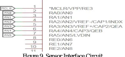
Figure 9. Sensor Interface Circuit
Its provision for 3 Voltage and 3 current signals, Sensed using onchip ADC,Voltage sensors are Potential transformers and Current
Sensors are ACS 712 hall effect sensors. As the motor is 3 phase, three voltages &
3-currents which can monitor, so made provisions for these 6 signals to monitor. For voltage monitor used step down type potential transformers & for current sensing used ACS712 hall effect current sensors which have a range of 30Amps.
In this fig shown 3 Voltage sensors and 3 current sensors. As the motor is 3 phase we have three voltages and three currents which we can monitor.The ACS712 sensors are connected to ADC channel 0 to 2 and the Voltage sensors are connected to ADC channel 3 to 5.
IX. EXPERIMENT RESULTS
[image:8.612.169.445.172.304.2]Simulation provides useful insight into operations. Proteus Simulink can be considered as essential tool for simulation of microcontroller. The speed controller algorithms using PIC 18F4431 microcontroller to increase the speed-sensorless drive.
Figure 11. Sine Time period & Phase timing
All sine wave form have time period = 20ms,
[image:8.612.154.455.355.502.2]Time between successive phase waveforms is = 6.70ms=120.6 degree
Figure 12. Phase details
Peak to Peak time between successive wave forms is = 6.70ms=120.6 degree
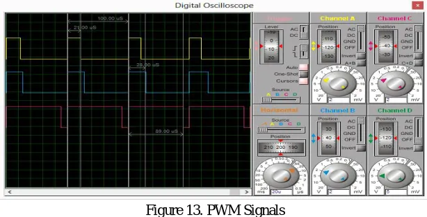
Figure 13. PWM Signals
[image:8.612.146.453.534.690.2]Figure 14. Sine wave Y and B phase 50 Hz
[image:9.612.128.472.244.391.2]All sine wave form have time period for 1 complete cycle= 20ms, means Fsine = 50Hz
Figure 15. PWM while stopping motor
All pulse wave form have time period for 1 complete cycle =167us. Fpwm = 1/(167e-06) = 5988.02Hz
So, Fsine = 5988.02Hz/200 = 29.94Hz
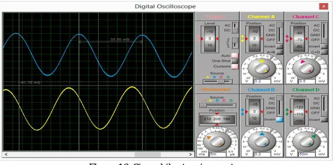
Figure 16. Sine while stopping motor
Time period for 1 complete cycle = 33.50ms So, Fsine = (1/33.50e-03) = 29.85Hz
X. CONCLUSION
In this paper, shown economical robust speed observation and tracking performances even at load variation or variable-speed operation, shows that the proposed algorithms observe and correct respectively the speed over the entire speed range.
[image:9.612.136.467.456.620.2]REFERENCES
[1] A.K Rawal, Director “Traction rolling stock, three phase technology” published by Indian Railways institute of electrical engg (IRIEEN), in 18 Aug 2010. [2] FA Samman, Tajuddin Waris ,Tiara Dwi Anugerah, Muhammad Nuralim Zain Mide, “Three-phase Inverter Using Microcontroller for Speed Control
Application on Induction motor”, 2014 Makassar International Conference on Electrical Engineering and Infonnatics (MICEEI) Indonesia 26-30 November 2014.
[3] Zonal electric traction training centre avadi, Chennai, ISO 9001: 2000 certified “Study Material for 3 Phase Locos Course (WAP5/WAP7/WAG9)”, © ZETTC/AVD April 2008.
[4] Intel,“80186/80188 HIGH-INTEGRATION 16-BITMICROPROCESSORS”. Nov 1994, copyright © INTEL corporation, 1995.