Technology (IJRASET)
A Novel Modus of Hand Gesture Controlled
Wireless Robot
Rishi Raj Singh1, Rituparna Das2, Koushik Pal3 1,2,3
Department of Electronic and Communication Engineering, Guru Nanak Institute of Technology (Kolkata)
Abstract: In this Paper we are presenting an accelerometer based hand gesture controlled robot using Atmega8, one of the most basic microcontrollers. To increase the use of robots where conditions are not certain such as fire fighting or rescue operations, robots can be made which follow the instruction of human operator and perform the task. The robot can be moved in any direction just by making simple hand gestures, and the system’s sensitivity to gestures can be easily adjusted as per our liking. This is an easy, user-friendly way to interact with external fields. An accelerometer is used to detect the tilting position of your hand, and a microcontroller gets different analogue values and generates command signals to control the robot. This concept can be implemented in a robotic arm used for handling hazardous instances, such as in military. The Android platform used for latest mobile devices can also be applied for controlling such type of robot
Keywords: Accelerometer sensor, Atmega8 Microcontroller, Motor driver, Smartphone, Encoder and Decoder, Wi-Fi Module, RF receiver and transmitter.
I. INTRODUCTION
The global focus on terrorism and security may have geared up following the attacks all over the world. The risk of terrorist attack can perhaps never be eliminated, but sensible steps can be taken to reduce the risk. Nowadays tracking enemies at different areas are very much difficult for soldiers. There may be a chance of lost of lives of the soldier during war and emergency situations. Programming and control of a robot through the use of the robot teach pendant is a tedious and time-consuming task that requires technical expertise. Therefore, new and more intuitive ways for robot programming and control are required. The goal is to develop methodologies that help users to control and program a robot, with a high-level of abstraction from the robot specific language. In the robotics field, several research efforts have been made to create user-friendly teach pendants, implementing intuitive user interfaces such as colour touch screens, a 3D joystick. But, neither of these techniques is efficient to control the robot as they do not give accurate results and have slow response time. When it comes to robot communication the technique adopted should be such that it can cover wide distance and provide good battery backup. When these aspects are considered ZigBee is a better option than the others. So the idea is to replace a real soldier with robot soldier.
II. EASEOFUSE
There are sound, light, magnetic field and other sensors that help the robot to collect information about its environment. There are Processors powered by powerful software that help the robot make decisions by sensing environmental data that is captured and also microphones, speakers, displays, etc that help the robot interact with humans. So, we have proposed a model of a robot based on “Accelerometer Based Gesture Controlled Robot” utilizing hand gestures to communicate with embedded systems for tracking of enemies. The 3-axis accelerometer is selected to be the input device of this system, capturing the human arms behaviours. When compared with other common input devices, especially the teach pendant, this approach using, accelerometer is more intuitive and easy to work, besides offering the possibility to control a robot by wireless means. Using this system, a non-expert robot programmer can also control a robot quickly and in a natural way.
III. IMPLEMENTATIONS
A. Software used
We are using Atmel Software to program the microcontroller as well as the “C Programming Language”.
B. Hardware used
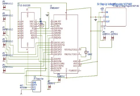
can see application of microcontroller in Fig.-2 and 4.[1][2]
2) DC Motor: It converts DC power into mechanical power, based on the principle that when a current carrying conductor is
placed in a magnetic field, the conductor experiences a mechanical force. The speed is controlled by changing the applied voltage to armature or changing the field current.[1]
3) Accelerometer Sensor: The ADXL335 is a small, thin, low power, complete 3-axis accelerometer with signal conditioned
voltage outputs. It has 6 pins among which 3 pins are dedicated for X, Y and Z axes. It is a sensor that records acceleration and gives an analogue data while moving any one of the directions.[3][4]
4) L293D Motor Driver: It is a dual H-bridge motor driver Integrated Circuit(IC). It amplifies the low output current signal from
microcontroller to control the movement of direction of motors(clockwise & anti-clockwise). The driver has 16 pins.[5]
5) Encoder: HT12E[8], a series encoder is used, capable of encoding information using its 18 pins.[6]
6) Decoder: HT12D[9], a series decoder is used, capable of decoding the encrypted information enhancing the security of the
overall system. It also has 18 pins.[6]
7) RF Transmitter & Receiver Module: RF stands for Radio Frequency which is available in different operating ranges. We have
used the RF Module along with a pair of encoder and decoder. It can transmit signal up to 500ft of range at rate of 1-10Kbps. Transmitter receives serial data and transmits RF signal wirelessly to the receiver through antenna. Receiver module consists of 8pins used for receiving RF signal from the transmitter.[7][10].
Figure 1: Block Diagram of Robot.
[image:3.612.61.563.309.706.2]Technology (IJRASET)
Figure 3:- PCB Layout of RF Receiver.
[image:4.612.77.560.364.697.2]Figure 5:- RF Transmitter PCB Layout.
IV. CONTROLSTRATEGY
The robot is controlled by accelerometer sensor, which is communicating with main circuit by using Radio Frequency (RF) and we are also using smart-phone which is communicating with main unit through Wi-Fi. The robot is moving based on human hand position in the free space in which is calculated by using two accelerometer sensors.
Now, we are using in-built A/D converter of ATMEGA8 microcontroller, which feeding output of accelerometer sensor directly to the microcontroller.
After the conversion and evaluation on defined condition by microcontroller, then the set output from processor is fed to the encoder which will encode the message and send it through RF transmitter, to the RF receiver and decoded by decoder and as per the decoder’s output, motor driver will control the motors. The full control flow explain in figure 6.
Again, for Smart-phone based system, first of all Wi-Fi broadcasting will start. Then we will connect our smart-phone with the device and as per the user’s command the robot will execute.
[image:5.612.162.469.446.705.2]Technology (IJRASET)
V. RESULT&DISCUSSION
As per the given conditions the robot will control its movement
A. For RF (Accelerometer Sensor) Based System
1) Case-1: If ((YA> 0) and (YB> 0))
[image:6.612.215.416.150.318.2]Then robot will move forward.
Figure 7: Robot moving forward.
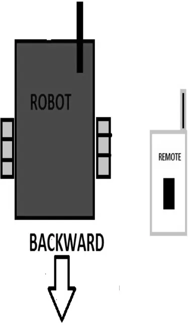
2) Case-2: If ((YA<0) and (YB> 0))
Then robot will move backward.
[image:6.612.225.412.369.693.2]3) Case-3: If ((YA>YB) Then robot will turn left.
Figure 9: Robot turn left.
4) Case-4: If ((YB>YA)
Then robot will turn right.
Figure 10: Robot turn right.
5) Case-5: If ((XA>XB)
Then robot arm will be opened.
6) Case-6: If ((XB>XA)
Then robot arm will be closed. Where,
XA is value of x-axis of accelerometer sensor A. YA is value of y-axis of accelerometer sensor A. XB is value of x-axis of accelerometer sensor B. YA is value of y-axis of accelerometer sensor B.
B. For Wi-Fi Based System
After the start of broadcasting, the user will pass command through Wi-Fi network. If user clicks on “Forward”, then the robot will move Forward.
If user clicks on “Backward”, then the robot will move Backward. If user clicks on “Left”, then the robot will turn Left.
Technology (IJRASET)
VI. COMPARISONWITHEXISTINGSYSTEM
Advantages are Unmanned robotics and gesture controlled robotic devices are being actively developed for both civilian and military use to perform a variety of dull dirty and dangerous activity. In many applications of controlling robotic gadget, it becomes quite hard and complicated when there comes the part of controlling it with remote or many different switches. The concept of using gestures to control machine with the movement of hand which will simultaneously control the movement of robot, which is a benefit. When compared with other common input devices, especially the teach pendant, this approach using, accelerometer is more intuitive and easy to work, besides offering the possibility to control a robot by wireless means. Using this system, a non-expert robot programmer can also control a robot quickly and in a natural way. The main objectives of using robot are where man dares not venture, to rescue under precarious conditions and we can even make them to go to war. Wireless modules consume very low power and are best suited for wireless, battery driven devices. Advanced robotic arms that are designed like the human hand itself can easily controlled using hand gestures only. Proposed utility in fields of Construction, Hazardous Waste, Disposal, Medical Science, Omni-directional Tread Mills may produce a feel of physical places during simulated environments. [3]
VII. CONCLUSIONS
As we all know, these days our nation is sick of massive terror attacks and bomb explosions. To avoid such disasters technological power must exceed human power. Human life and time are priceless. We completed our project “Accelerometer Based Gesture Controlled Robot”, which is an efficient circuit (robot), which can be moved in any direction by making simple gestures. Since the circuit is wireless and as we have used Atmega8 microcontroller to realize the circuit because it has some additional features when compared to the basic microcontroller 8051, it posses an in-built ADC and DAC, pulse with modulation feature, high resolution etc. In this project, we used rechargeable battery so that the robot is very reliable. The accelerometer sensor on android smart-phone can also be used as a motion control of robots. Overall, the control process goes well. The farther the distance between the smart-phone and the robot, the slower the response time of robot in motion. The whole system explain in fig- 1 and PCB layout of RF receiver and transmitter is shown at fig-3 and 5.
REFERENCES
[1] electronic circuits and devices, millmen and halkias [2] the 8051 microcontroller, majjidi and majjidi
[3] http://www.analog.com/media/en/technicalDocumentation/data-sheets/adxl335.pdf. [4] ADXL335 Datasheet by sparkfun.
[5] www.robotix.in.
[6] “Digital Electronic” by A.Anand Kumar publish by PHI.
[7] “accelerometer based gesture controlled robot using arduino” by swarnaprabha jena, sworaj kumar nayak, saroj kumar sahoo, sibu ranjan sahoo, saraswata dash, sunil kumar sahoo at international journal of engineering sciences & research technology
[8] http://www.holtek.com/pdf/consumer/2_12ev120 .pdf [9] http://www.eleinmec.com/datasheets/ds_holtek_ ht12d.pdf [10] http://oap.sourceforge.net/datasheets/rf.pdf
[11] “A New Type of Wireless Hand Gesture Controlled Robot” presented by Rishi Raj Singh et all at “8th All India Inter Engineering College Academic Meet 2017” organized by “Forum of Scientists Engineers & Technologists (FOSET)”
[12] ESP8266EX Datasheet Version 4.3 Espressif Systems IOT Team http://bbs.espressif.com [13] http://www.wikipedia.or