6
Chapter 2 Literature Survey
2.1 Introduction
This chapter provides an introduction and a summary of the key literature that has been consulted for this research. Creating a framework to provide multicast services for mobile nodes in a wireless communication network is a challenging issue.
The relevant published research has been surveyed in the fields of multicast delivery, multicast mobility and multicast handover within WiFi networks. This framework can support both IPv4 and IPv6 WiFi environments, so the key protocol information and literature review in this chapter will be discussed and focuses on IPv4 and IPv6 environments.
This chapter begins with an overview of multicast delivery concept and protocols. It will then go on to a review of multicast mobility protocols and problems within WiFi networks. After that, the processes and problems of multicast handover are examined. Following this, details about multicast handover issues and approaches will be investigated. Finally, a brief summary is given for the chapter.
2.2 Multicast Delivery
In the IP network system there are three types of communication in a network:
Unicast Delivery – one source is sending a single transmission of data directly
to one destination.
Broadcast Delivery – one source is sending the data to all destinations in the
network.
Multicast Delivery – one source is sending the data to a select group of
7
[image:2.595.128.466.380.727.2]In traditional computer networks, data is typically sent from a source node to a destination node known as unicast delivery, which is suitable for most applications in the network; alternatively, one source node can transmit a copy data to all end point destination nodes and then the destination nodes will decide if they want to use those data or not known as broadcast delivery. One benefit of broadcasting is that it reduces loads at source node from duplicating data that are sent for multiple destination nodes. The source node sends only one copy of the data to the broadcast address and then the network devices on the network will duplicate the data and transmit to cover the network. However, there are some kinds of application that need to send the same data to multiple destination nodes such as multipoint videoconferencing, online gaming and live TV. It will waste bandwidth on the network if it uses the process of unicast delivery to support those applications. Hence, the aim of multicast delivery is to deliver data packets between one source to multiple destinations more efficiently.
8
The concept of multicast delivery was introduced in the late 1980s by Stephen Deering [3, 4]. The idea is to transmit a single copy of IP packet to a group of destinations, which is identified by a same multicast IP address. A main factor in multicasting is bandwidth efficiency in the network. The multicast functions and protocols have evolved over time as refined in RFC 3376 [5], RFC 4604 [6] and so on.
Multicast is the delivery of data packet to a group of user devices using a common IP multicast destination address. When a multicast tree is set up, the source starts sending IP datagram to the host group address. Then, the network devices take on the responsibility for sending the IP datagram to all destinations within multicast group. Multicast routers along the path are responsible for ensuring that datagrams are transmitted over the appropriate links to ensure they reach all hosts of the multicast group.
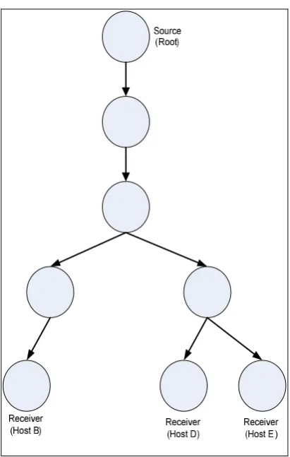
[image:3.595.133.390.484.703.2]The process of coping datagrams occurs only when paths diverge at a multicast router, thus reducing the bandwidth consumption on the network. Figure 2-2 is shown an example of multicast delivery in a TCP/IP (Transmission Control Protocol / Internet Protocol) network. The arrows represent the direction of multicast delivery packets that are sent to host B, host D and host E in the network.
9
In networking, the term multicast is synonymous with IP multicast. Multicast delivery is a technique for delivery datagrams from one source to multiple destinations over the network. The optimal distribution paths are created after the member in the multicast group joins in the multicast tree in real time. Multicast delivery technique and group management can support a large number of destination nodes without needing to know how many destination nodes there are. Multicast group requires the source node to send a request to join message only once, even if there are a large number of receive nodes to be sent. IP multicast has an efficient process to maintain the members within the multicast group.
The model of the multicast group is known as an open and dynamic group. This means that, the source node can send multicast packets at any time when it is ready, with no need to announce, register or schedule transmission. The only one thing that the source node needs to know is a multicast address. Also, it is not necessary for the source node to know about group membership in advance. The host members in the multicast group can join or leave a multicast group at any time. However, source and destination multicast nodes can communicate to each other via IP multicast group address. Sources use the multicast IP address as the destination address in their sending data stream. Destination hosts use multicast IP address to notify the network device that they want to receive those packets that are sent to this multicast tree. However, the destination host has to send “join message” to be a member of the multicast group first.
In order to deliver multicast data stream, the network creates a “multicast tree”. The multicast tree construction is begun with network devices close to the destination nodes and is thus receiver-driven. The multicast tree is built for that group once there are members in a particular IP multicast group and maintained by “multicast routing protocol”. There are several kinds of multicast routing protocol depending on the network. Also, each one of them has its own unique method and technique. More information about multicast routing protocols will be given in a later section.
2.2.1 Benefits of Multicast Delivery
10
Live multimedia services such as video, radio, television etc., are delivered as multimedia streaming services. These services require large bandwidth allocations and if they are delivered as separate streams for each user, this will place huge demands on network resources. Hence, multicast delivery can help to control network traffic and reduce this problem [8]. This advantage is known as optimized performance, because multicast delivery eliminates traffic redundancy on the network. Figure 2-3 illustrates a multicast tree, which is represented in Figure 2-2.
[image:5.595.195.401.252.576.2]
Figure 2-3 Multicast Tree
11
Moreover, in 1994, a host in Japan was found to require a bandwidth over the entire MBONE (Multicast Backbone) of 650 kbps for video streaming. However, if compared with the bandwidth requirement for digital TV, there is a big difference. SDTV (Standard-definition TV), with MPEG-2 compression, will require 2-5 Mbps and 1.5-2 Mbps with MPEG-4 compression. On the other hand, the bandwidth requirement for HDTV (High-definition TV) is increased about five times, 15-20 Mbps with MPEG-2 compression and 5-10 Mbps with MPEG-4 compression [11].
In addition, another advantage of multicast is enhanced efficiency by reducing loads on central media servers in terms of CPU (Central Processor Units) power, memory usage and protocol management. Network routers also only need to manage and maintain one data stream per multicast service [12]. However, routers do have the added burden of needing to maintain knowledge of which devices belong to which multicast tree and to manage routing along these trees.
By using multicast delivery, video streaming application can offer a higher quality service because the load for single multicast delivery is less than multiple unicast delivery [13].
The network bandwidth saving is the main point expected of multicast’s effect on the network. Hence, network providers normally must consider the cost of managing, maintaining and implementing multicast. However, the main factor is bandwidth. R. Chalmers and K. Almeroth [14] defined a metric to compare the performance between unicast and multicast delivery. The metric compares the total number of links traversed by unicast and multicast datagrams on a given network infrastructure. The metric refers to each links as a hop in the route path of a single multicast or unicast datagram.
= 1 − (2.1)
Where
Multicast hops are the total number of multicast links in the distribution link in the
network.
12
is the multicast metric which is a fraction in the range 0 ≤ ≤ 1.
marks the percentage increase in the bandwidth utilization achieved by using multicast more than unicast delivery. For this metric if the value of is zero, this means the number of hops is the same. If the has a value of nearly one, it means the performance of using multicast delivery is higher compared to unicast.
Due to the number of multicast members being dynamic, new nodes and destinations can join and leave the multicast group at will. This means the multicast group size always changes over time, especially in a real time application. J. Chuang and M. Sirbu [15] presented a cost function of path, which is related to equation 2.1 and defines a direct relationship between the hop counts and the size of multicast group.
= (2.2)
Where
is the total multicast distribution tree length is the average length of unicast routing path N is the size of multicast group
k is the economies of scale (EoS) factor.
The range of value k is between 0 and 1, which is the value of the slope of the graph relationship between normalized tree cost and multicast group size. For most of the topologies investigated in their experiment, which is in real and generated networks, it is shown that ≈ . .
Now assuming = will get:
= − (2.3)
13
= − ≈ . − ≈ − . (2.4)
So
≈ − . (2.5)
Equation 2.5 gives us an estimate for the multicast performance, which is based on the number of destination nodes in the multicast group.
Another advantage of multicast is distributed application, as multicast makes multipoint applications possible. The example applications of multicast services are provided in the following.
Multimedia Conferencing Online video/audio streaming Interactive distance learning Online TV
Group online gaming Video on Demand (VoD) Commercial stock exchanges
However, a major problem with this kind of application is the lack of reliable delivery of data because multicast delivery is UDP protocol based, not TCP protocol. There are some multicast disadvantages such as [13]:
Best Effort Delivery: dropping packets are to be expected. Therefore, multicast
applications should be designed accordingly and should not expect high reliability of packet transmission. Packet losing should be accepted on those applications.
Duplicate Packets: some multicast protocol techniques such as registers,
14
Same Video Stream: only one copy of multicast stream is sent to all users in
the same multicast group, so every user receives the same data stream at the same time. Hence, individual users cannot choose the content they want, and also they cannot pause the video stream, rewind it or skip some parts.
Specific content: in the multicast network, it is more complicated to control the
users’ access to specific streaming content because all users in the same group access the data at the same time.
Out of Order Delivery: as multicast is based on UDP protocol, some routing
protocol techniques may also result in packets being out of order. Hence, multicast applications should be designed to solve the issue of out of order packets arriving.
2.2.2 Functions of Multicast Delivery
This section provides a brief overview of the important functions of multicast delivery.
Multicast Address Management: This function is about the assignment and the scope
of multicast address.
Multicast Service Announcement and Discovery: These services allow destination
hosts to discover the availability of multicast source. In TCP/IP network, the SAP (Session Announcement Protocol) protocol handles this function [16].
Multicast Group Management: Handles the collection and maintenance members of
the multicast group. In IPv4 network, IGMPv2 (Internet Group Management Protocol version 2) protocol deals with this function. The counterpart in IPv6 network is MLD (Multicast Listener Discovery) protocol.
Multicast Routing: Multicast Routing protocols are responsible for the multicast tree
15
Path First), PIM-DM Independent Multicast Dense Mode), PIM-SM (Protocol-Independent Multicast Sparse Mode), DVMRP (Distance-Vector Multicast Routing Protocol) and Core-Based Trees (CBT) [17].
Reliable Multicast Transport: This function is to ensure the reliable delivery of
multicast stream to a potentially large destination group.
Multicast Mobility: Multicast delivery mechanism designs for static receiver.
However, the mobile source and destination moves create issues for delivering the multicast data such as how to keep connection, managing IP address in a new location and so on. Solving these problems is a big challenge. This research has investigated this function in some depth and proposed a new framework to achieve the required functionality of this function.
According to multicast delivery, it is not only the way to send one message source to many destinations but also it can send from many sources to many destinations. Moreover, in a mobile environment this means the source could possibly move. In terms of a mobile source, these are divided into Any Source Multicast (ASM) and Source-Specific Multicast (SSM) [18].
ASM is where a mobile node submits data to any source in a multicast tree via an ASM group and either creates the root of a source-specific shortest path tree (SPT) forwarding datagram to a rendezvous point (RP) or destinations, or it distributes packets directly down a shared tree.
16
2.3 Multicast Protocols in IP Networks
The aim of this section is to review the standard protocols, which are related to the multicast services within the network. In a TCP/IP network, the protocol responsible for multicast group management is MLD protocol for IPv6 network and IGMP protocol for IPv4 network. Hence, in the next section MLD protocol will be the focus.
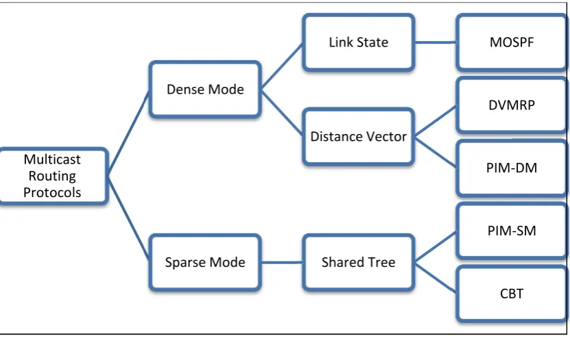
[image:11.595.83.499.311.558.2]Multicast routing protocols use algorithms to build multicast distribution trees. Each routing protocol is different in regards to how they share content, information and create paths [19]. Figure 2-4 is shown the classification of the intra-domain multicast protocols.
Figure 2-4 Intra-domain routing protocols [20]
A brief summary of these multicast routing protocols are as follows:
MOSPF: This protocol is an extension of the OSPF routing protocol in unicast
delivery. The MOSPF protocol uses the link-state algorithm the same as OSPF to create the paths with minimum protocol traffic overhead [20]. Moreover, if the number of multicast groups and group member size increase the computational complexity of the link-state algorithm will increase also [21].
Multicast Routing Protocols
Dense Mode
Link State MOSPF
Distance Vector
DVMRP
PIM-DM
Sparse Mode Shared Tree
PIM-SM
17
DVMRP: This protocol defined in 1988 by Waitzman, Partridge and Deering,
was the first multicast routing protocol, which was deployed over the MBONE network [22]. This protocol is an extension of the RIP routing protocol in unicast delivery and extends to multicast network [21].
PIM: It is a popular multicast routing protocol standard in TCP/IP network.
This research has modified the protocol in the framework. In the following section PIM protocol will be discussed in detail.
CBT: This protocol was defined in 1997 [23]; it is a shared tree protocol and
cannot create a source-based tree.
2.3.1 MLD Protocol
Multicast data delivery comprises both local and global techniques in which local techniques are responsible for multicast group management. Global techniques are responsible for multicast routing. For LAN multicasting each node can choose whether it wants to receive multicast data or not. Multicast destination nodes will inform the network device that they want to receive data packets that are sent to the multicast group.
This process is called a “join” and is controlled by the IGMP protocol in an IPv4 network and controlled by the MLD protocol in an IPv6 network. In this research, global mechanisms are managed by the PIM protocol (Protocol Independent Multicast), which is multicast routing protocol in intra-domain network. For local mechanisms we chose to work with MLD protocol [24].
18
Receiver nodes on a route keep an interface state for every IPv6 multicast address from which they want to receive data stream per interface [26]. The interface state on a receiver node contains a record including a filter mode and also source list for each multicast IP address [20].
2.3.2 PIM Protocol
To support multicast communication, a multicast routing protocol is required. For this research we consider the PIM protocol because PIM is one of the most popular shared tree multicast routing protocols. There are two types of PIM protocol, namely PIM-DM, which was defined in 2005 [27] and used in environments where multicast trees are populated densely within the network. Another type is PIM-SM defined in 1998, which is better suited to sparsely populated networks.
In this research we are focusing on the PIM-SM protocol because it is designed to support large region networks such as the internet. Sparse mode is activated when multicast groups are thinly populated across a large network region. This mode is designed for that situation. However, PIM-DM builds a separate source-based tree for every source, while a shared tree has been used for all sources within a multicast group.
All multicast sources in the tree transmit all multicast stream traffic to the root, and then the root forwards the multicast traffic to all destination nodes in the network. Normally, multicast sources encapsulate their multicast data in unicast data packets addressed to the RP router within the multicast tree. When the RP receives those packets, the RP will decapsulate these packets and then forward them over the multicast delivery tree to all members in the multicast group [20].
19
There are many control messages, which are used within the PIM-SM protocol. The PIM-SM message can show the following parts:
Bootstrap message
PIM-SM control-message encapsulation
Hello message
PIM-SM packet header
Encoded Unicast Address field
Join/Prune message
Encoded Group Address field
Candidate RP advertisement
Encoded Source Address field
Register message
Assert message
Register-Stop message
2.4 Multicast Mobility in WiFi Network
In this section, a review of mobility within the wireless network will be presented, including multicast mobile and related protocols.
2.4.1 Overview of WiFi Network
20
Table 2-1 A data rate and coverage area of wireless technologies [28]
Network type Frequency Data Rate Coverage Bluetooth 2.4 GHz ISM
band
Max 721
kbps 0.1-10m
IEEE 802.11a 5 GHz 20 Mbps 50-300 m
IEEE 802.11b 2.4 GHz 11 Mbps Up to 100 m IEEE 802.11g 2.4 GHz 54 Mbps 30-150 m
IEEE 802.16
(WiMAX) 10-66 GHz
Max 70
Mbps Over 50 km
IMT2000, UMTS 2 GHz Max 2
Mbps 30m-20km
GPRS (GSM), EDGE (HSCSD)
900, 1800, 1900 MHz
9.6-384
kbps Up to 35 km
2.4.2 Mobility in WiFi Networks
In IPv6 wireless network, the protocol that provides mobility support is Mobile IPv6 protocol, and this protocol will maintain the connection when the mobile node moves. Also, it includes the responsibility for the reachability of the mobile node and network, keeping records and IP address. So, in the next section the protocols that are related with mobility will be presented.
2.4.2.1 Mobile IPv6 Protocol
21
In contrast, the care-of-address is a temporary address provided for a 'foreign' network and this address will change as the device moves between different IP subnetworks. The care-of-address in IPv6 network can be formed based on stateless or stateful mechanisms [30]. When the mobile node moves, it first forms a care-of-address based on the prefix of the foreign link. Then, the mobile node sends a Binding Update (BU) message to the home agent, which is its temporary care-of-address (CoA).
[image:16.595.194.402.337.469.2]After that, although the home agent wants to grant or deny the request from the mobile node, the home agent will send a registration message reply [31]. After the registration process is successful, any messages destined for the mobile node are intercepted by the home agent, which encapsulates the packets and tunnels them to the foreign agent. Then, the data streams are forwarded to the mobile node [32].
Figure 2-5 Mobile IPv6 Protocol
Mobile IPv6 offers improvements in this process compared to Mobile IPv4. For example, Mobile IPv6 can eliminate the triangular routing issue and produces route optimization. Route optimization is the process that enables the correspondent node to reroute data stream on a direct path to mobile destination [33].
22
2.4.2.2 ICMPv6 Protocol
The ICMPv6 (Internet Control Message Protocol version 6) protocol [34] is used to carry IP control messages for various purposes such as destination unreachable, time exceeded and parameter problem. In addition, ICMPv6 is defined to carry information between hosts, between routers, or between hosts and routers.
There are two types of ICMPv6 message [35]:
ICMP error message
The functions of ICMPv6 error messages are to report forwarding or delivery errors by either a router or the destination node. The ICMPv6 error messages consist of destination unreachable, packet too big, and parameter problem and so on.
ICMP informational message
Informational messages provide simple diagnostic functions such as echo request, echo reply, and additional host functionality for example MLD and ND (Neighbour Discovery), which is a set of processes and messages that determine relationships between neighbouring devices.
2.4.3 Multicast Mobility in IPv6 WiFi Network
When a mobile node moves from one network to another network, it is a challenging problem to maintain reachability and transparency of a mobile node. In case of multicast wireless network, the scenario of handover is particularly challenging and serval issues emerge with most solutions due to the handover impacts.
The main problem when the receivers move is multicast latency problem. Multicast latency
problem, whenever an MN moves to a foreign network, the delay experienced by executing
handover process.
23
(Multicast listener discovery) query/report messages including a request to join a multicast tree. In this case, the maximum query period of MLD is up to 125 seconds [36]. For some applications, this increased latency time is undesirable such as video conferencing.
Run-liu, W and Yun-hui [37] proposed a multicast routing algorithm trying to reduce the cost of created multicast tree combines with Mobile IP. Also this algorithm tries to reduce the bandwidth of multicast data stream. For applying to large scale of wireless network and reducing join delay time in handover process.
Holbrook, Cain and Haberman [38] proposed a new approach called the Mobile Multicast Protocol (MOM) in 2003. This approach introduces a new entity called the designated multicast service provider (DMSP) and uses a foreign agent entity. The main issue of this research is to reduce the duplicated multicast packets on home agent. However, it created the problem between the HA and FA networks.
Figueiredo, Jeon and Aguiar [39] proposed the solution to reduce vertical handover by adapting a cross layer approach and IEEE 802.21 Media-Independent Handover. There is the process of selected FA links in the network. Also the process uses the single tunnel for completing the delivery process.
2.4.4 Multicast Mobility in UMTS Network
For 3G (UMTS) mobile networks, multicast can be delivered through IP multicast, MBMS (Multimedia Broadcast/Multicast Service) and CBS (Cell Broadcast Service). CBS is a standard that allows the delivery of messages to multiple users in both GSM and UMTS networks. Similarly, MBMS is a standard that is designed to support efficient multimedia broadcast and multicast delivery in GPRS and UMTS networks.
24
2.5 Multicast Mobility Problems in WiFi
Networks
2.5.1 Multicast Mobility Problems
Although the research area of multicast mobility has been a concern for about 10 years, there are numerous proposals but not yet a generally accepted standard solution. One reason for this is that the standard multicast protocol was designed for stationary nodes and not for mobility. The problem and challenge of multicast mobility can be divided into 3 categories [40]:
Multicast routing problems: due to the movement of mobile nodes and the source
there are routing problems, such as:
Network inactivity: means when the foreign network the mobile node visited
does not support multicast delivery. Hence, the mobile node has to stop receiving the multicast message.
Core placement: when the mobile node moves to a foreign network, the new
route will be established. If the mobile node changes zone more often, the frequent handovers can lead to a situation that those multicast routers are off centre. That results in a possible non-optimality configured path.
Multicast Encapsulation/Decapsulation: a variety of methods are used for
tunnels to keep connection between the mobile node and home network when the mobile node moves to foreign network.
Mobile receiver problems: In multicast routing when the MNs are moving, they need
25
Packet loss: a mobile node may miss some multicast data because when it
moves normal multicast packets will continue to be delivered to the home network for a short period of time.
Packet duplication: happens when the mobile node receives the packet from a
different multicast router but from the same multicast tree.
Packet out of order: when handover occurs.
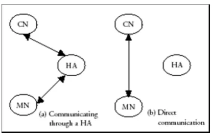
Tunnel convergence problem: the tunnel convergence problem is concerned
[image:20.595.150.437.406.655.2]with the delivery of multicast packets to mobile member nodes that are located in several foreign networks over bi-directional tunnels using Mobile IP. An MN receives multicast packets from a home agent, duplicated multicast packets are transmitted to over several tunnels and these become a problem [36].
Figure 2-6 Tunnel convergence problem [36]
Mobile source problems: In multicast mobility, it is not only the mobile node that can
26 considered:
o Transparency: is a major problem when a multicast source moves. There is a
problem with the CoA of the multicast source, because when a mobile source uses a new CoA as a multicast source address, it cannot send multicast messages immediately. It has to wait until the mobile node explicitly notifies that CoA[41].
o Reverse path forwarding (RPF): because it is specific to source location.
o Packet loss.
o Source active problem: because the multicast tree has to be reconstructed
when the mobile source moves to the new network.
2.5.2 Overview of Handover Problem
Currently, there are several wireless technologies to provide ubiquitous information access to users when they are moving. A mobile device such as a smart phone offers multiple wireless network interfaces and can access these as it moves between different network environments.
Typically, when a mobile device is within the building they receive signals from WiFi and 3G at the same time but choose WiFi for data services. However, when they move out of the building, they will be receiving only the 3G signal. The smart phone will, of course, automatically switch between these networks when WiFi connectivity is lost.
For wireless networks, there are two types of handover that can occur in the network.
Horizontal handover
Horizontal handover is the process by which mobile devices switch from one cell to another cell within the same network technology; this will be called “intra-system handover”.
27
For vertical handover or “inter-system handover” the mobile device is switching between different network technologies; for example between 3G and WiFi. That means that vertical handover is different in several aspects such as data rate, bandwidth and frequency of operation.
Moreover, vertical handover can be divided into two sub types, which are upward-vertical handover and downward vertical handover [20]. For example, the device moves from WiFi to 3G. Downward vertical handover is a handover that disconnects from a cell providing broader coverage to a wireless overlay with a smaller cell size, and generally higher bandwidth per unit area such as from 3G to WiFi.
2.5.2.1 The Handover Process
One of the major problems of multicast mobility is the handover process which occurs between cells or between different technologies. The handover process can be divided into three phases [8],[28].
Network Discovery or System Discovery: This phase is where the mobile node (MN)
searches for reachable wireless networks, usually based upon values of received signal strength.
Handover decision: These are the rules that determine when a mobile node should
perform handover. A decision for vertical handover may depend on various parameters such as bandwidth, delay and transmitted power.
Handover Implementation or Handover Execution: This is the process by which a
mobile node’s connection is rerouted from their existing network to a new network in a seamless manner. Mostly, it requires the network to transfer routing information about the mobile terminal.
28
modifying the Mobile IP protocol [28,19,42]. Other approaches operate at the transport layer and at the application layer such as a modification to SIP (Session Initial Protocol) [43].
For the Network Discovery Phase, the MN must search for available reachable wireless networks. In this state most MNs should always keep all network interfaces on. However, keeping network interfaces on all of the time becomes a weakness because it consumes battery power without any benefit of delivering real data.
In [8], the context information about a network is stored in the context awareness database. Many parameters are collected by system discovery and are dependent on the adopted network interface card within the MN. For instance, these could include signal RSSI (Received Signal Strength Indicator), bit rates, MAC (Media Access Control), etc.
In addition, network monitoring systems adopt SNMP (Simple Network Management Protocol) to extract more relevant network information from all APs (Access Points) and ARs (Access Routers) in each subnet such as data transmission/receiving rate, network loading and multicast connections.
2.5.2.2 Handover Decision Phase
There are many research papers proposing strategies for making decisions about handover. We categorize these into three types: network-controlled handover, mobile-controlled handover and mobile-assisted handover.
Network-controlled handover is when the network makes the handover decision for a mobile node. Shantidev Mohanty [45] proposed a novel architecture using the Network Inter-operating Agent called NIA and Integration Gateway (IG) to integrate the 3G systems and WiFi networks of various providers. The IG functions as a traffic monitoring unit and seamless roaming module.
29
domain. The MAG-MLM uses a MAG (Mobile Access Gateway) to detect the detachment of the MN.
The LMA-MLM uses a LMA (Local Mobility Anchor), which is responsible for maintaining the reachability of MNs by updating the binding cache and maintaining the tunnel to the MAG for packet delivery. Their process can achieve the whole multicast handover process without the involvement of the MN. However, the LMA-MLM still has to deal with the problem of encapsulation.
Kim and Han [46] have proposed PMIP protocol with IP multimedia system. The protocol that they proposed naming PMIP-M protocol. The main idea of this protocol is the user can continue received multicast data stream even when they migrates in the new network which without IP multicast capability.
Mobile-controlled handover is where the mobile node must take its own signal strength measurements and make the handover decision on its own. In [47], an algorithm is proposed based on the Markov decision process (MDP) formulation, which tries to maximise the expected total reward of a connection.
Mobile-assisted handover is where the decision to handover is made by the mobile node and network in cooperation. In [43] a mobile QoS (Quality of Service) framework is proposed for heterogeneous IMS (Internetworking Management System) interworking by modifying SIP multicast. However, this method consumes network bandwidth and MNs need to reserve bandwidth. Park and Won [48] analyse about mobility management architecture such as MIP and PMIP protocol for avoiding any tunnels for multicast delivery in heterogeneous network.
30
One thing that is important when the handover occurs is considering the handover metrics used to make the decision. There are many handover metrics that are used to indicate when handover should be performed:
Connection cost
For users, connection cost is a key consideration, especially when different network operators may create different billing schemes. Hence, it might affect the user’s choice of handover.
Network-related parameters
There are many network parameters used for making the decision such as bandwidth, load, network latency, traffic congestion, location information and so on. Moreover, that information is useful for load balancing across different networks and QoS [20].
Application types
For example, some multimedia applications require reliability in networks. Hence, different types of applications may require different levels of QoS determined by the percentage of lost packets or the delivered data rate.
Battery power
Battery power may be a significant factor for handover in some cases. Moreover, an MN with multiple interfaces must keep an interface active all the time but this consumes battery power even without receiving any data.
2.5.2.3 Handover Implementation
Several multicasting schemes have been proposed for mobile networks. In [44] they used the ISHO (inter-system handover) protocol and include the concept of a dynamic boundary area to support seamless roaming between different networks. However, this scheme requires the NIA and IG to be added into the network architecture.
31
EAP-AKA is the Extensible Authentication Protocol method for UMTS Authentication and Key Agreement used for authentication in wireless networks. They are divided into two phases: Initial phase and Key refresh phase. The benefit of this technique is that it saves communication overhead, computation overhead and does not need a huge change for existing protocols [50].
2.5.3 Handover within WiFi Networks
For the WiFi-3G handoff process, [51] a method is proposed to reduce latency by using the ISHO (inter-system handover) protocol which includes the concept of a dynamic boundary area to support seamless roaming between different networks. However, most of this research tries to solve the problem in the network layer with others seeking to solve it by modifying the transport layer. For instance, in [52] a mobile QoS framework is proposed for heterogeneous IMS interworking by modifying SIP multicast. However, this method consumes network bandwidth and MNs need to reserve bandwidth.
The handover procedure of Mobile IPv6 protocol can be expressed as 2 parts: L2 (link layer) handover latency and L3 (network layer) handover latency. The L2 handover consists of channel scanning process, authentication and association process. Generally, L2 handover latency is about 100 – 300 ms however it depends on the structure of network topology. For L3 handover latency in MIPv6 consists of two main parts: CoA configuration and Binding update. The process of CoA configuration is starting from Router discovery process until the MN obtained a new CoA. The Binding update procedure is about the MN inform HA and CA nodes about their new location which is new CoA address. Normally, handover latency of Mobile IPv6 is about 2000-3000 ms [53] this is why it is possible that MN can lose connection completely during handover process.
32
mechanism among LMAs (Local Mobility Anchor) to solve a bottleneck and single point of failure issues.
2.5.4 Multicast Handover in Wireless Networks
For streaming multimedia content in 3G network has been standardized under the 3GPP-PSS (3rd Generation Partnership Project – Packet Switched Streaming Standard) which is released in April 2001. The 3GPP-PSS are described presentation of information, the audio and video formats of that stream within complete protocol stack in IP layer [56]. In UMTS, the IMS was extended to include MBMS. The 3GPP MBMS has the following characteristics:
There is no immediate Layer 2 source-to-destination transition, resulting in transit of all multicast traffic at the GGSN.
As GGSNs commonly are regional, triangular routing, distant entities and encapsulation this may cause a significant degradation of efficiency.
In 3GPP2 (3rd Generation Partnership Project 2) [57], the MBMS has been extended to the Broadcast and Multicast Service (BCMCS) [58], which on the routing layer operates very similar to MBMS. In both 3GPP (3rd Generation Partnership Project) and 3GPP2, multicast can be sent using either point-to-point (PTP) or point-to-multipoint (PTM) tunnels, and there is support for switching between PTP and PTM.
A mobile multicast node may change its point of Layer 2 attachment within homogeneous access technologies (horizontal handover) or between heterogeneous links (vertical handover) [59]. In [60] has modified PIM-SM to support handover latency and keeping connection. By proposed multicast routing protocol named MC-PIM-SM by extended from PIM-SM protocol [61]. Mobility applications transport for MIH are required as an abstraction for Layer 2 multicast service transfer in an Internet context [45] and are specified in [62].
Functions required for MIH include:
33 Service discovery.
Service invocation.
Service context transformation.
In [63] is shown the amount of multicast packet loss, when handover occur at the mobile node in equation. Suppose ( ) is the amount of multicast packet loss for the base multicast handover procedure. Let denote the average multicast session arrival rate per second at the mobile node. ( ) is obtained as
( )
= ( ) ( ) (2.6)
Where E(S) is the average session length in packets
This research will focus on mobile receiver problems and so methods to solve these problems have been proposed. The problem of achieving seamless mobile receiver multicast handover can be addressed by one of the following:
Home subscription-based solution:
o Mobile IP Home Subscription or bi-directional tunnelling: this approach relies
on the Mobile IP protocol and uses a local router in the home network as the multicast router for responses such as forwarding multicast group membership control messages to the mobile node even when it moves to a foreign network. However, tunnelling will create the process of encapsulation/ decapsulation and fragmentation problems.
o Multicast encapsulation: that is encapsulation of multicast data packets to
shield mobility and to enable access to remotely located data services such as from the home agent.
Remote subscription-based solution: by forcing the mobile node to re-initiate
34
o Agent assistance: there are many protocols that are proposed for agent-assisted
handover for host-based mobility such as Fast MIPv6 (FMIP6) and Hierarchical MIPv6 (HMIPv6).
o Network-based mobility management: Proxy MIPv6 (PMIPv6) [19] is
multicast transparent in the sense that the MN experiences a point-to-point home link fixed at its LMA (Local Mobility Anchor). In [63] network based mobility management is deploying for the mobile nodes, also the tunnel between the LMA and itself for the MN. However, PMIPv6 still has a problem about MTU size from spanning tunnels at the receiver site.
Hybrid architectures: that tries to find the methods, which avoid the complexity at
the internet core network.
o Hybrid shared tree: [64] proposes the hybrid shared tree approach by
introducing a mobility-agnostic multicast backbone on overlay.
o Hierarchical local registration: the network model has proposed hierarchical
and local registration. The registration consists of having a root FA (Foreign Agent) and lower FAs. The MN registers its CoA with the root FA. All the FAs exchange summary reports that consist of the common multicast group of interest on the lower levels. However, this approach required an extra cost to select multicast service provider (MSP) [65].
MLD Extensions: there are many methods by extended MLD message. Some of them
modify an MN operating predictive handover such as FMIPv6.
2.6 Summary
35
make use of bi-directional tunnelling, which means that the framework solves three problems: tunnel convergence, encapsulation / decapsulation overhead delay, and fragmentation problems.
![Figure 2-1 Comparison between Unicast, Broadcast and Multicast transmission [2]](https://thumb-us.123doks.com/thumbv2/123dok_us/8705977.880749/2.595.128.466.380.727/figure-comparison-unicast-broadcast-multicast-transmission.webp)
![Figure 2-2 Multicast delivery [7]](https://thumb-us.123doks.com/thumbv2/123dok_us/8705977.880749/3.595.133.390.484.703/figure-multicast-delivery.webp)
![Table 2-1 A data rate and coverage area of wireless technologies [28]](https://thumb-us.123doks.com/thumbv2/123dok_us/8705977.880749/15.595.133.465.128.408/table-data-rate-coverage-area-wireless-technologies.webp)
![Figure 2-6 Tunnel convergence problem [36]](https://thumb-us.123doks.com/thumbv2/123dok_us/8705977.880749/20.595.150.437.406.655/figure-tunnel-convergence-problem.webp)
