International Journal of Emerging Technology and Advanced Engineering
Website: www.ijetae.com (ISSN 2250-2459, ISO 9001:2008 Certified Journal,Volume 3, Issue 8, August 2013)
282
Manual Driven Platform Cleaner
Prathmesh Joshi
1, Akshay Malviya
2, Priya Soni
31,2,3Department of Industrial & Production Engineering, Jabalpur Engineering College, Ranjhi Road, 482001, Jabalpur, India
Abstract— Many investments are made for maintaining hygiene in railways these days and various equipment are used by Indian railways for this purpose. Platform rider scrubber or platform cleaning machines from different companies are purchased by Indian railways in recent times.
As the technology grows there are more inventions in the field of machinery. Many of them are serving cleaning and hygiene maintenance.
This project report is based on the “Manually Driven Platform Cleaning Machine” which serves the basic needs of cleaning large floor areas especially Railway Platforms.
Cleaning problems at various railway platforms and bus stations. As there is no adequate electricity in Jabalpur region, the use of automatic cleaning machine is not favourable.
Keywords—Cross-belt, Pedal Axle, Steering Mechanism, Scrubber Brush, U-Clamps
I. INTRODUCTION
Presently available platform scrubber is electrically operated and cannot work by any other means. These platform scrubber are quite expensive and have a high maintenance cost as per our research done in Indian railways. In our project we have invented a manually
driven platform cleaning machine that serves
approximately the same functions as available in present electrically operated machine.
A floor cleaning machine has housing and a movable hood that covers over vacuum and liquid hoses of the machine that are visible in prior art floor cleaning machines. The vacuum and liquid hoses are each pivotally connected to a wall of the machine housing and are also pivotally connected to a transparent dome provided on the hood. These connections reduce stresses on the hoses when the hood is moved and allow the dome to pivot relative to the hood. The floor cleaning machine also has a pair of slit orifices that eject fan spray patterns of cleaning liquid that are non-coplanar and do not intersect each other. Furthermore, the floor cleaning machine has an oscillating brush assembly that includes a brush that is replaceable without using tools. The brush height can be adjusted via an adjustment member.
The structure of the machine is rigid and robust to provide a comfortable platform to the rider. Essential the structure is also designed for the minimum maintenance cost and most of parts used are interchangeable.
The main parts combining to form the overall structure are discussed below:
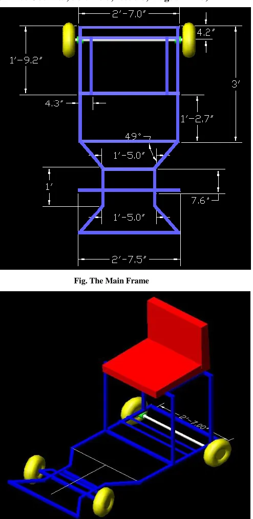
II. THE MAIN FRAME
The main frame used is designed especially to serve it purpose of overall floor cleaning. The whole structure is made up of heavy gauge square iron pipe having dimensions (1.5” * 1.5”) so that it may handle and bear the load of the rider and all the equipment that are to be fit on it to complete the wholestructure.
1. Rear Wheels
Rear wheels are connected to a rear axle. In the rear axle one of the rear wheels is rigidly connected and the other one is made free to rotate about the axel. This is done so as to overcome the slipping of wheels during turning. This principle is used in low cost vehicles where differential gear is not economical. (Tire radius = 7 inches)
2. The Rear Axle
International Journal of Emerging Technology and Advanced Engineering
Website: www.ijetae.com (ISSN 2250-2459, ISO 9001:2008 Certified Journal,Volume 3, Issue 8, August 2013)
283 This main frame is connected using hub and bearings supported with iron clamps and then fastened by nut and bolds. The rear wheels also have the bearing hub arrangement, so that they may be fixed to the rear axle. (Total length of the rear axle = 3’-4”).
3. Front Wheels
The front wheels are almost same in structure and size as that of the rear wheels. The only difference in the front wheels is that both the wheels are free to rotate about the axle. These front wheels are fastened to the axle using nuts of required size. (Tire radius = 7 inches)
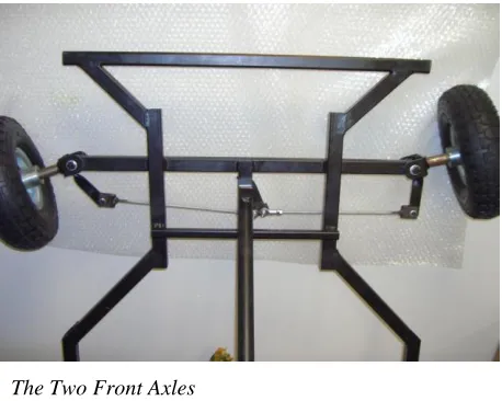
4. The Two Front Axles
The front axle is divided into parts separately for the two wheels. Since the front wheels are connected to the steering mechanism and hence for the rotation of the machine they align themselves through the steering mechanism. To the front two axles are fastened the wheels using the nut and the axel is connected to the main frame using “U” clamps.
5. “U” clamps
The two “U” clamps connect the front axles and the main frame and hence allowing the front axles to rotate about the vertical axes. The “U” clamps are nothing but U shaped cast iron clamps especially designed to hold the front wheels and at the same time rotating them about the vertical axes.
6.Pedestal Frame
[image:2.612.54.283.275.458.2]Two vertical rods are attached to the main frame so that the pedestal bearings may be fixed to them. This frame is again a square pipe of dimensions (1” * 1”).
Figure : Pedestal Bearing
7.Pedestal Bearings
Two Pedestal bearings are used to provide a rigid guide to the pedestal rod through which the main scrubber is attached. These pedestal bearings are easily available in the market.(pedestal bearing no. = 4).
8.Scrubber Brush
The scrubber brush that is used is same as that used in the present rider scrubber (electrically powered). This brush is also easily available in the market on demand. The scrubber brush is circular in shape that when rotates cleans the floor effectively.
9. Front Brush
The front brush used in this machine is the simple spring loaded brush ensuring the brushing up of the big dirt particle coming on the way of cleaning floor. This brush is fixed at the very first portion of the machine.
International Journal of Emerging Technology and Advanced Engineering
Website: www.ijetae.com (ISSN 2250-2459, ISO 9001:2008 Certified Journal,Volume 3, Issue 8, August 2013)
284 Figure: Front Brush
10. Steering Mechanism:
A rotating pair steering mechanism is used for smooth turning of the machine. This type of mechanism is used because of its low weight and cost and is sufficiently rigid
for suchmachines. The steering mechanism consists of two
fixed plates on “U” clamps. These plates are connected with the steering rod using chuck nuts so that they are free to rotate about the nut bolts. This steering system is known as steering knuckles system where the axles are mounted on a knuckles, out and away from the main frame, and they actually rotate around these pivots, and cause the wheels to turn.
There actually is a relationship in the wheels to a turned center, and there is a positioning system on these steering knuckles which is important for steering.
11. Pedal Frame
Pedal frame is a mounting on the main frame on which the pedal axle is held. The pedal frame is the inverted V type of frame which has a “connecting T” on it, on which the specially designed pedal axle is held. The “connecting T” used is the one which is used in cycle rickshaw.
12. Pedal Axle
Pedal axle used is the specially designed axle on which the pulley and the pedal freewheel is fixed. This freewheel is connected to the rear gear through the chain drive. This pedal axle has two pedals attached to it.
13. Pedal Axle Gear
Pedal axle gear is small in size as compared to the gear attached on rear axle. This is done to decrease the speed of the machine so that it can give considerable time to the floor area and clean efficiently.
14. Pulleys
Two pulleys are used in the mechanism. A smaller pulley is attached to the pedestal rod and the bigger one is attached to the pedal axle. This is done to increase the RPM of the rotating brush. These two pulleys are connected by the cross-belt.
15. Cross-belt
The application of the cross-belt reduces the bulkiness of the mechanism in order to transform to motion from one axis to the other perpendicular axis. Many cross-belt application can be seen in various machineries.
16. Chair
The chair is placed at a position where the worker finds himself comfortable for performing his tasks. Every part of the machine such as pedals, steering etc. are under reach of the person.
17. Rear wiper
In an order to make the cleaning more effective rear wipers are provided at the end of machine. This wiper carries the dust which the front wiper fails to trap.
18. Water tank
It is placed in the space which is provided below the chair. This tank provides the water to the scrubber brush and rear wiper for wiping the surface. Its size may be adjusted according to the size and the load carrying capacity of the frame of the cleaner.
III. COMPARISON OF ELECTRIC VS MANUAL
International Journal of Emerging Technology and Advanced Engineering
Website: www.ijetae.com (ISSN 2250-2459, ISO 9001:2008 Certified Journal,Volume 3, Issue 8, August 2013)
285 There is a 1 H.P. motor that is used in the electric model consuming nearly 12 units of electricity per day(assuming 3 platforms cleaned)so 400 units per month costing nearly 2500/-,a manually driven model saves this consumption of electricity as well as the sum for further developments. The electric model needs a wire for connection to a power source by which a lot of accidents take place which can be avoided using the manually driven model. To operate the electric model a much skilled labor is needed whereas in
case ofthe manually driven model all what is needed to be
[image:4.612.335.582.128.635.2]done is just to pedal and steer which can be done by any layman thus reduction in labor payment can be achieved. Moreover, there will be job vacancies rising for the less or unqualified people of the belonging to rural areas of the nation. Due to the Fact that it is less costly and having low maintenance, more than one machine can be put into use thereby doing the same amount of work in a very less time as compared to the electrically driven machine thereby saving a lot of the valuable time. Since the sources from which electricity is generated are getting exhausted day by day in a very rapid rate this manually driven platform cleaning device will be helpful in raising the economy of the country causing a huge fund to get raised in the Indian Railways thereby reducing the railway fares and ultimately the various taxes paid by a normal person making the life better on the individual basis. Since the manually driven machine needs no motor to work, it is completely noise free and hence maintaining a comfortable environment for the passengers present at the railway station. The manually driven platform cleaning machine has not even a single bit of complexity in the working procedure. The equipment used in the machine are so designed that they are not subjected to unbearable stresses thereby increasing the working period of the machine. The seat for the rider is so designed that it will be providing utmost comfort to the rider and hence the rider could work with machine for a longer period of time on daily basis or could do the same cleaning work at any other place where it is required. The time taken for the manually driven machine for doing a piece of work is the same as that of the time taken by the electrically driven machine.
Fig. The Main Frame
International Journal of Emerging Technology and Advanced Engineering
Website: www.ijetae.com (ISSN 2250-2459, ISO 9001:2008 Certified Journal,Volume 3, Issue 8, August 2013)
286
[image:5.612.50.288.148.451.2]IV. SPECIFICATIONS
Fig. View of Pedal Axle Mechanism
Fig. Alternate Scrubber Mechanism
Fig. Manually Driven Platform Cleaning Machine
REFERENCES
[1] WESTERN INDIAN RAILWAYS, Jabalpur Division.
[2] Race Car Vehicle Dynamics : William F. Milliken, Douglas L. Milliken.
[3] Fundamentals of Automobile Body Structure Design : Donald E. Malen.
[4] Tire and Vehicle Dynamics : Hans B. Pacejka.
[5] The Automotive Chassis : Jornsen Reimpell, Helmut Stoll, Juergen W. Betzler.
[6] Vehicle Noise, Vibration, and Sound Quality : Gang Sheng (Gang Sheng Chen).
S. No. Component Measurement
1. Main Frame 1.5” * 1.5”
2. Rear Axle 3’4”
[image:5.612.45.290.467.674.2]