Improvement of semi-active control
suspensions based on gain-scheduling control
Husam Hammood
School of Computing, Science & Engineering
University of Salford
Salford, UK
Submitted in Partial Fulfilment of the Requirement of
the Degree of Doctor of Philosophy
I
LIST of CONTENTS
1 INTRODUCTION ... 1
1.1 Introduction ... 1
1.2 Identification of the Problem ... 2
1.3 Research Motivation, Aim and Objectives ... 4
1.4 Contributions of This Thesis ... 5
1.5 The Layout of the Thesis ... 6
2 BACKGROUND ... 8
2.1 Introduction ... 8
2.2 Railway Vehicle Suspension Systems ... 10
2.2.1 Primary Suspension ... 11
2.2.2 Secondary Suspension ... 11
2.3 Control Schemes in Suspension ... 13
2.3.1 Passive Suspension Systems ... 14
2.3.2 Full-Active Suspension Systems ... 15
2.3.3 Dynamic Response of the Actuator for a Full-Active Suspension... 16
2.3.4 Semi-Active Suspension Systems ... 17
2.3.5 Semi-Active Dampers ... 18
2.4 Design Considerations and Requirement ... 20
2.5 Track Inputs ... 23
II
3 LITERATURE REVIEW ... 27
3.1 Introduction ... 27
3.2 Full-active Suspension Systems ... 28
3.2.1 Configurations of Suspension Technologies ... 28
3.2.2 Control strategies... 30
3.3 Semi-Active Suspension Systems ... 33
3.3.1 Control Strategies ... 33
3.4 Summary ... 38
4 MODELLING AND CONTROL OF THE RAILWAY VEHICLE ... 40
4.1 Introduction ... 40
4.2 Analytical Model ... 40
4.3 Vertical Dynamic Model ... 43
4.4 Lateral Dynamic Model ... 50
4.5 Full-Active Suspension System ... 61
4.5.1 Skyhook Damping ... 61
4.5.2 Model Decomposition ... 63
4.6 Application of Full-Active Control to Vertical Suspensions ... 65
4.7 Application of Full-active Control to Lateral Suspensions ... 69
4.8 Conventional Semi-Active Suspension System ... 71
4.9 Summary ... 73
III
5.1 Introduction ... 74
5.2 MR Fluid... 74
5.3 MR Damper ... 75
5.4 Modelling of the MR Fluid Damper ... 76
5.4.1 Modified Bouc–Wen Model for MR Damper ... 77
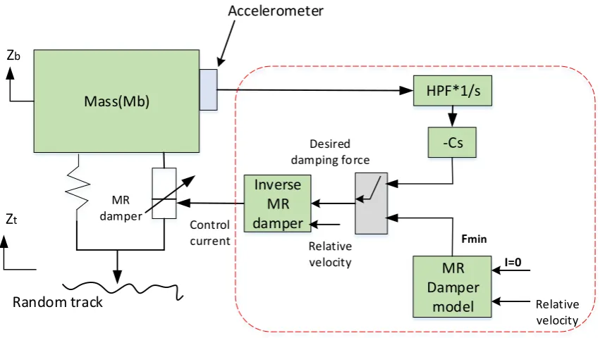
5.5 Local Controller for MR Damper Based Semi-Active Systems... 81
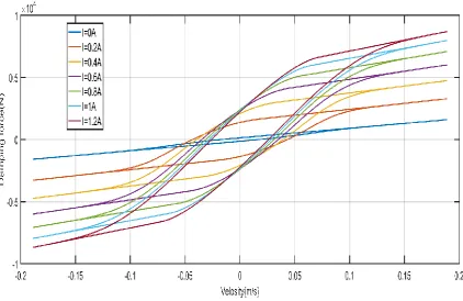
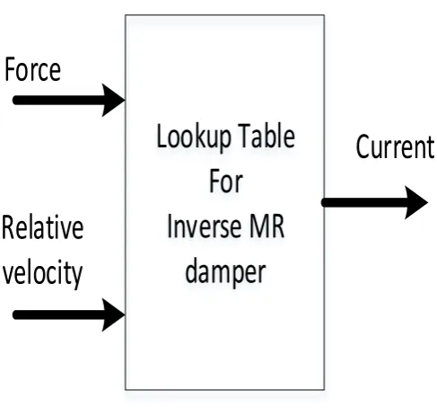
5.6 Inverse Model of MR Damper ... 82
5.7 Summary ... 87
6 SEMI-ACTIVE SUSPENSIONS BASED ON GAIN-SCHEDULING CONTROL89 6.1 Introduction ... 89
6.2 Semi-Active Controller based on Gain-Scheduling ... 90
6.3 Control Strategies ... 91
6.4 Design Process and Tuning ... 97
6.5 Application to Vertical suspension (tuning) ... 98
6.6 Application to lateral suspension (tuning) ... 100
6.7 Force Filter Tuning ... 102
6.8 Summary ... 104
7 NUMERICAL SIMULATION OF VERTICAL SECONDARY SUSPENSION 105 7.1 Results of Vertical Secondary Suspension ... 105
IV
8.1 Results of Lateral Secondary Suspension ... 125
8.2 Summary ... 144
9 CONCLUSIONS AND FUTURE WORK ... 146
9.1 Conclusions ... 146
9.2 Recommendations for Future Work ... 148
10 APPENDIX: LIST OF PUBLICATIONS ... 150
V
LIST OF FIGURES
Figure 1.1: Force – velocity diagram for semi-active damper[15] ... 4
Figure 2.1: Diagram of a railway vehicle model (a) vertical model; (b) lateral model ... 10
Figure 2.2: Use of improved active secondary suspension performance[19] ... 13
Figure 2.3: Conventional passive, semi-active, and full-active suspension systems[20] ... 14
Figure 2.4: Force-velocity diagram for a passive damper[22] ... 15
Figure 2.5: Principle of an active suspension system [23] ... 16
Figure 2.6: Actuator force controller[15] ... 16
Figure 2.7: Semi-active suspension system ... 18
Figure 2.8:Semi-active damper concepts[22] (a) on-off category; (b) continuously variable category ... 19
Figure 2.9 :Semi-active damper characteristics in the time domain[22] (a) on-off damper, (b) continuously variable damper ... 19
Figure 2.10: Design process [20] ... 22
Figure 4.1: Schematic representation of the airspring in vertical secondary suspension of the railway vehicle ... 44
Figure 4.2: Schematic representation of the actuator in vertical secondary suspension of the railway vehicle ... 47
Figure 4.3: Schematic representation of the MR damper in vertical secondary suspension of the railway vehicle ... 49
Figure 4.4: Schematic representation of the passive damper in lateral secondary suspension of the railway vehicle ... 51
VI
Figure 4.6: Schematic representation of the MR damper in lateral secondary suspension of
the railway vehicle ... 58
Figure 4.7:The skyhook damping concept [25] ... 62
Figure 4.8: Schematic of the skyhook damping control system [25]... 62
Figure 4.9:Trade-off between ride quality and suspension deflection[15] ... 63
Figure 4.10: Schematic of the modal control diagram ... 64
Figure 4.11: Schematic of the full-active of vertical suspension system based on the modal control structure ... 65
Figure 4.12: Diagrams of the electro-mechanical actuator [65] ... 66
Figure 4.13: The equivalent mechanical model of the electro-mechanical actuator [65] ... 67
Figure 4.14: The PID local controller for the electromechanical actuator... 69
Figure 4.15: Schematic of the full-active of lateral suspension system based on the modal control structure ... 70
Figure 4.16: Schematic of the semi-active control system with the MR damper ... 72
Figure 5.1: Changes to ferromagnetic particles in an MR fluid ... 75
Figure 5.2: Cross-section of typical MR fluid damper[104] ... 76
Figure 5.3: The modified Bouc–Wen model for the MR damper ... 77
Figure 5.4: The damping force versus velocity (1 Hz, ±20 mm/s) ... 80
Figure 5.5: The damping force versus velocity (2 Hz, ±15 mm/s) ... 80
Figure 5.6: Lookup table for the inverse model of MR Damper ... 83
Figure 5.7: Single mass model with semi-active controller ... 84
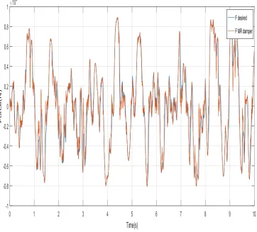
Figure 5.8: Validation of the inverse model ... 86
Figure 5.9: Comparison of MR damper forces under the random track ... 86
VII
Figure 6.3: Semi-active control based on gain scheduling for lateral suspension model ... 95 Figure 6.4: Tuning process of gain-scheduling semi-active control for vertical suspension ... 99 Figure 6.5: Tuning process of gain-scheduling semi-active control for lateral suspension ... 101 Figure 6.6: Comparison desired force without force filter and desired force filter damping force at the front suspension ... 103
Figure 6.7: Comparison acceleration response at the front suspension ... 103 Figure 7.1: Vertical acceleration comparison at the centre of the vehicle body using computer-generated track data input ... 107
Figure 7.2: Vertical acceleration comparison at the front of the vehicle body using computer-generated track data input ... 108
Figure 7.3: Vertical acceleration comparison at the rear of the vehicle body using computer-generated track data input ... 108 Figure 7.4: PSD of vertical comparison acceleration at the centre of the vehicle body using computer-generated track data ... 109
Figure 7.5: PSD of vertical comparison acceleration at the pitch of the vehicle body using computer-generated track data ... 110
Figure 7.6: PSD of vertical comparison acceleration at the front of the vehicle body using computer data ... 110
Figure 7.7: PSD of vertical comparison acceleration at the rear of the vehicle body using computer data ... 111
VIII
Figure 7.9: Vertical acceleration comparison at the rear of the vehicle body using measured track data input (track1) ... 114
Figure 7.10: Vertical acceleration comparison at the rear of the vehicle body using measured track data input (track1) ... 115
Figure 7.11: Vertical acceleration comparison at the centre of the vehicle body using measured track data input (track2) ... 115
Figure 7.12: Vertical acceleration comparison at the front of the vehicle body using measured track data input (track2) ... 116
Figure 7.13: Vertical acceleration comparison at the rear of the vehicle body using measured track data input (track2) ... 117
Figure 7.14: Vertical acceleration comparison at the centre of the vehicle body using measured track data input (track3) ... 117
Figure 7.15: Vertical acceleration comparison at the front of the vehicle body using measured track data input (track3) ... 118
Figure 7.16: Vertical acceleration comparison at the rear of the vehicle body using measured track data input (track3) ... 118
Figure 7.17: PSD of vertical accelerations at the centre of the vehicle body using measured track data input (track1) ... 119
Figure 7.18: PSD of vertical accelerations at the pitch of the vehicle body using measured track data input (track1) ... 120
Figure 7.19: PSD of vertical comparison acceleration at the front of the vehicle body using measured track data input (track1) ... 120
IX
Figure 7.21: PSD of vertical comparison acceleration at the centre of the vehicle body using measured track data input (track2) ... 121
Figure 7.22: PSD of vertical comparison acceleration at the pitch of the vehicle body using measured track data input (track2) ... 122
Figure 7.23: PSD of vertical comparison acceleration at the centre of the vehicle body using measured track data input (track3) ... 122
Figure 7.24: PSD of vertical comparison acceleration at the pitch of the vehicle body using measured track data input (track3) ... 123
Figure 8.1: Acceleration comparison at the front of the vehicle body using computer-generated track data ... 127 Figure 8.2: Acceleration comparison at the centre of the vehicle body using computer-generated track data ... 127 Figure 8.3: Acceleration comparison at the rear of the vehicle body using computer-generated track data ... 128 Figure 8.4: PSD of lateral acceleration at the centre of the vehicle body using computer-generated track data ... 129 Figure 8.5: PSD of yaw comparison acceleration at the yaw of the vehicle body using computer-generated track data ... 129
Figure 8.6: PSD of lateral comparison acceleration at the front of the vehicle body using computer-generated track data ... 130
Figure 8.7: PSD of lateral comparison acceleration at the rear of the vehicle body using computer-generated track data ... 130
X
Figure 8.9: Acceleration comparison at the front of the vehicle body using measured track data (track1) ... 133
Figure 8.10: Acceleration comparison at the rear of the vehicle body using measured track data (track1) ... 134
Figure 8.11: Lateral acceleration at the centre of the vehicle body using measured track data (track2) ... 134
Figure 8.12: Lateral acceleration at the front of the vehicle body using measured track data (track2) ... 135
Figure 8.13: Lateral acceleration at the rear of the vehicle body using measured track data (track2) ... 135
Figure 8.14: Acceleration comparison at the centre of the vehicle body using measured track data (track3) ... 136
Figure 8.15: Acceleration comparison at the front of the vehicle body using measured track data (track3) ... 136
Figure 8.16: Acceleration comparison at the rear of the vehicle body using measured track data (track3) ... 137
Figure 8.17: PSD of lateral acceleration at the centre of the vehicle body using measured track data (track1) ... 138
Figure 8.18: PSD of lateral acceleration at the yaw of the vehicle body using measured track data (track1) ... 138
Figure 8.19: PSD of lateral acceleration at the front of the vehicle body using measured track data (track1) ... 139
XI
Figure 8.21: PSD of lateral acceleration at the centre of the vehicle body using measured track data (track2) ... 140
Figure 8.22: PSD of lateral acceleration at the yaw of the vehicle body using measured track data (track2) ... 140
Figure 8.23: PSD of lateral acceleration at the front of the vehicle body using measured track data (track2) ... 141
Figure 8.24: PSD of lateral acceleration at the rear of the vehicle body using measured track data (track2) ... 141
Figure 8.25: PSD of lateral acceleration at the centre of the vehicle body using measured track data (track3) ... 142
Figure 8.26: PSD of lateral acceleration at the yaw of the vehicle body using measured track data (track3) ... 143
Figure 8.27: PSD of lateral acceleration at the front of the vehicle body using measured track data (track3) ... 143
XII
LIST OF TABLES
Table 4.1: Vehicle parameters of the vertical model ... 46
Table 4.2:Vehicle parameters of the lateral model [28, 65]... 54
Table 4.3:Variables and parameters of the electromechanical actuator[65] ... 68
Table 5.1:MR damper parameters[28] ... 79
Table 5.2: Lookup table for the inverse model of MR damper ... 84
Table 6.1: Controller coefficients of gain-scheduling semi-active control for vertical suspension and ride quality improvement... 98
Table 6.2: Controller coefficients of gain-scheduling semi-active control for lateral suspension and ride quality improvement... 100
Table 7.1: Ride quality and suspension deflection results from time simulation under random track irregularities ... 106
Table 7.2: Ride-quality improvements and suspension deflection results using measuring track data input (track1) ... 111
Table 7.3: Ride-quality improvements and suspension deflection results using measuring track data input (track2) ... 112
Table 7.4: Ride-quality improvements and suspension deflection results using measuring track data input (track3) ... 113
Table 8.1: Ride quality and suspension deflection results using computer-generated track data input ... 125
Table 8.2: Ride quality and suspension deflection results from time simulation using measured track data input (track1) ... 131
XIII
XIV
DEDICATION
This PhD Thesis is dedicated to all members of my family: My parents, who live abroad and kept their hearts with me.
My wife, for her support and patience with me throughout my PhD.
XV
ACKNOWLEDGEMENTS
I would like to acknowledge with deep appreciation the academic guidance, understanding and continuous encouragement provided by my supervisor, Professor T X Mei throughout this study. His patience and inspirational guidance was extremely valuable on the successful completion of this work.
Also, I would like to thank my parents, my brothers and sisters, my wife, and my family for supporting me throughout this PhD study and my life in general. Thank all my friends for their encouragement and support during my study for the PhD degree.
I would like to acknowledge the financial and academic support of University of Dhi Qar and University of Salford, particularly the award of scholarship that provided me the necessary financial support for this research, library facilities, and the computer facilities.
XVI
ABSTRACT
---
XVII
1
CHAPTER ONE
1
INTRODUCTION
1.1
Introduction
Suspension systems play an essential part in improving the ride quality and stability of the vehicle system. It reduces the motion and acceleration of the sprung mass in the system. Conventional passive suspensions have some advantages such as design simplicity and cost-effectiveness. However, the performance due to the wide frequency range of excitations induced by track irregularities may be limited because of the associated fixed design, in which the damping and spring cannot be controlled when the system and/or operating conditions change.
Therefore, in the last decade, controllable suspension systems, which include full-active and semi-active systems, have been proposed by using computer-based control devices and controllable actuators [1, 2]. Although full-active suspension systems can provide high control performance over a wide frequency range of vibrations, the cost and high power requirement of the actuators imposes significant obstacles to their commercial adoption. A promising alternative to full-active suspension system is a semi-active suspension.
2
of vehicle suspension because of their fast response, low power consumption and ability to control the damping ratio [6].
However, the tracking of the desired damping force is a significant issue in semi-active suspension systems. The variable dampers are only capable of dissipating energy, but cannot develop a positive force when the damper velocity reverses and hence the semi-active controller will simply apply a damping force using passive mode; therefore, a semi-active damper cannot create the necessary forces, or apply the same level of control, in the same way as a full-active control in such conditions.
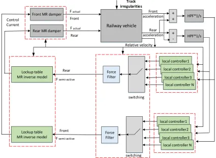
This study will focus on the development of a novel semi-active control strategy that aims to extend the duration of the active mode and hence reduce the duration of the passive mode for semi-active suspensions by using a gain-scheduling control structure that dynamically changes the control force demanded according to the operating conditions.
1.2
Identification of the Problem
Many control strategies have been studied for the semi-active suspension systems in the attempt to achieve high levels of performance. Most semi-active control strategies are based on achieving a control force equivalent to the behaviour of the skyhook control strategy[7]. Some linear feedback control methods and intelligent strategies have also been investigated in the semi-active suspension system [8, 9]. More recently, many control strategies including fuzzy logic control [10], skyhook, ground-hook and hybrid control[11], neural network predictive control algorithm[12], semi-active fuzzy control [13], and adaptive vibration control [14] have been explored.
3
devices such as MR dampers is that they are only capable of providing active control forces by dissipating energy, i.e., in their active mode, and are switched to work as simple passive dampers, i.e., the passive mode, when energy injection is demanded by the appropriate control laws. The split in durations of time between the active and passive modes for the conventional semi-active control strategies is around 50:50. In the full-active suspension system, the force-velocity diagram (Figure1.1) shows that the actuator force versus actuator relative force-velocity it works in all four quarters, which means the energy can be injected into the suspension system or dissipated from the suspension system.
However, the semi-active damper can only be dissipated energy from the system, which follows from the possibility to work only in the first and third quarter of the force-velocity diagram, as shown in Figure 1.1. Therefore, the semi-active damper is not able to develop a damping force in the opposite direction as the relative damper velocity, and it is switched to the minimum damper setting, i.e., in their passive mode, as the damper is transmitting the force rather than dissipating energy.
4
Figure 1.1: Force – velocity diagram for semi-active damper[15]
1.3
Research Motivation, Aim and Objectives
The aim of the research is to overcome the constraints of conventional linear control strategies and improve semi-active suspension to achieve a performance close to that of full-active control. The improved performance may be used to deliver the same level of the performance that is currently only possible with full-active suspension systems without incurring the associated high costs and power consumption.
The improved performance can be used to deliver a better ride quality or will be used to enable higher railway vehicle speeds while maintaining the same level of passenger comfort. The other possibility is to provide the same ride quality on less well-maintained or lower quality track.
5
Undertake a comprehensive literature review of current full-active and semi-active control strategies for suspension systems.
Undertake a comprehensive literature review of semi-active suspension control of the MR damper.
Work on the modelling and simulation of a railway vehicle as a case study and control design for active/semi-active suspension control.
Develop an adaptive control strategy for a semi-active suspension in order to minimise the use of minimum level of damper settings as much as possible.
Verify the development of the proposed control strategy via the MR damper model and assess the associated system performance.
Discuss dynamic performance and draw conclusions from the research carried out, and further make recommendations as to how the proposed control design for semi-active suspension of a railway vehicle can improve ride quality.
Publish results of research in journals, and present the same at conferences.
1.4
Contributions of This Thesis
This thesis presents the development of a non-linear control strategy for semi-active suspension that can be used to deliver a level of the performance that is only currently possible with full-active suspension without incurring the associated high costs and power consumption. This thesis is believed to make the following contributions to the present research field:
6
The proposed control method is applied to both vertical and lateral secondary suspensions of the railway vehicle in this study and the improvements in the ride quality are evaluated with several different track data.
1.5
The Layout of the Thesis
The thesis is organised as follows:In chapter 1, the introduction and an overview of the study are given, as well as a brief description of the motivation, aims, and objectives of this research.
In chapter 2, the background of thesis and an overview of different categories of control suspensions are presented. The advantages and limitations are briefly discussed.
In chapter 3, the comprehensive literature review of full-active and semi-active suspension systems for railway vehicles is presented. The use of an MR damper-based semi-active suspension for railway vehicles is also discussed. The literature review highlights the importance of this research.
In chapter 4, the modelling of the conventional railway vehicle in vertical and lateral directions are introduced. Vehicles with passive suspension, full-active and conventional semi-active controls are introduced as benchmarks and are used for comparative assessment of the proposed semi-active controlled suspension design.
In chapter 5, both the modelling and control of semi-active MR dampers are presented.
7
In Chapter 7, the numerical simulation results of vertical secondary suspension performed in the Matlab Simulink environment to evaluate and analyse the performance of different control strategies for the secondary suspension system of the railway vehicle are discussed.
In Chapter 8, the results of lateral suspension used to assess the performance of different control strategies for the secondary suspension system of the railway vehicle are further analysed.
8
CHAPTER TWO
2
BACKGROUND
2.1
Introduction
Increased velocity is one way for railway vehicles to compete with other means of transportation. However, higher velocity usually causes increased forces and accelerations on the vehicle, which negatively affect ride comfort. Therefore, some form of active technology in the secondary suspension system might represent a solution to improved ride quality in cases where conventional passive suspension systems cannot be further optimised. The improved performance can be used to deliver better ride quality or will be used to enable higher railway vehicle speeds while maintaining the same level of passenger comfort. The other possibility is to provide the same ride quality on lower quality track. In this regard, the active secondary suspension can be used in the lateral and/or vertical directions when different actuator configurations are installed.
The concepts of full-active suspension in railway vehicles have been studied theoretically and experimentally for decades, generally showing significant ride quality improvements compared to passive suspension systems. In full-active suspension systems, actuators, which are operating by the external power supply, are used to generate the necessary damping force to suppress the vibrations. However, active suspensions have disadvantages regarding their weight, size, high power consumption, and fail-safety issues[16].
9
passive suspension, full-active suspension systems must be safe and reliable in order to be considered a feasible option for industrial railway implementation[16, 17].
During the past decade, among the many different types of controlled suspension systems, the semi-active suspension has been investigated by a number of researchers for use in railway vehicles, automotive, and vibration control applications [5]. The semi-active suspension offer advantages over passive suspension in terms of its more desirable performance and, on the other hand, provides a more cost-effective solution when compared with full-active suspensions.
Semi-active suspension systems usually use controllable dampers to change the damping force, and do not add energy to the suspension system such as semi-active hydraulic damper changes the size of an orifice in the hydraulic flow valve to adjust the damping force, an electrorheological (ER) damper applies different of the electric field to control the viscosity of the ER damper.
More recently, Magnetorheological (MR) dampers, which can change the damping ratio by suitable magnetic fields, have been studied for railway vehicles in semi-active suspension by many researchers, because of their low power consumption, fast response, and the capability to control the damping ratio.
10
thereby increase energy dissipation, and for which there is significant potential for future implementation.
2.2
Railway Vehicle Suspension Systems
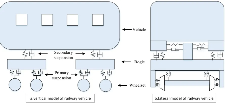
Prior to developing the controller, a model of a railway vehicle, which is shown in Figure 2.1, is constructed as the benchmark model for assessment and comparative studies of control strategies. The railway vehicle studied in the research is composed of one vehicle body, two bogies, and four wheelsets. The two bogies, which are identified simply as the front and rear bogies, are connected to the vehicle body by the secondary suspension. Each of the two bogies is also connected to two wheelsets by the primary suspension. The primary and the secondary suspensions are provided in the vertical and lateral directions. The main aim of active technology in railway vehicle suspension can fall into one of two categories: improving running stability and wheelset guidance through controlling the primary suspension, and improving ride quality through controlling the secondary suspension.
Vehicle
Bogie
Wheelset Secondary
suspension
Primary suspension
[image:28.595.77.523.482.687.2]a:vertical model of railway vehicle b:lateral model of railway vehicle
11
2.2.1 Primary Suspension
The most significant challenge in the primary suspension of railway vehicles is to achieve a good compromise between stability and guidance, which with a passive suspension is difficult. The critical speed of the railway vehicle on the straight track is a function of an exceedingly stiff wheelset guidance, especially in the longitudinal direction, and is often integrated with a stiff yaw damping between vehicle and bogie. However, the curving performance is thereby negatively affected, since a high primary suspension stiffness reduces the radial steering ability, which causes larger track shift forces and a higher amount of wheel and rail wear. With the actively controlled primary suspension, the stiffness can be adapted to the running conditions[16]. Active technology in the primary suspension can improve the curving performance whilst maintaining an adequate level of running on the straight track. The concept of active primary suspension has been under investigation for decades and has been theoretically and practically developed and improved. There are a variety of approaches to enhance stability and guidance through an active technology, which has been categorised and summarised by Goodall et al. [18]. However, high cost and reliability issue have prevented the implementation of this technology for active primary suspension.
2.2.2 Secondary Suspension
12
control of the secondary suspension is to provide better isolation of the vehicle from excitations transmitted from track irregularities than the passive damping can offer by itself, and hence improves passenger comfort. The secondary suspension is usually controlled in the lateral direction, including the yaw mode, or in the vertical direction, including the pitch mode. It is important to realise that the improved performance offered by an active suspension can be employed from an operational point of view through a variety of methods.
13
Figure 2.2: Use of improved active secondary suspension performance[19]
2.3
Control Schemes in Suspension
14 Track Body Bogie Track Control unit Semi-active Body Bogie Track Passive Body Bogie Control unit Power supply Full-active x xo x xo x xo
Fd Fd Fd
Figure 2.3: Conventional passive, semi-active, and full-active suspension systems[20]
2.3.1 Passive Suspension Systems
Passive suspension systems for railway vehicles using springs and pneumatic or oil dampers have some advantages such as cost-effectiveness and design simplicity. However, the performance due to the wide frequency range of excitations induced by rail track irregularities may be limited, and the parameters of the passive damper are fixed, which means that once the system is designed, the damping cannot be adapted. In addition, a fixed passive damper may become ineffective due to other phenomena such as instability of the vehicle, which is velocity dependent. In fact, when the railway vehicle velocity reaches a critical value, the amplitude of the railway vehicle vibration grows exponentially with time and theoretically reaches infinity in a linear system[21]. Figure 2.4 shows the relationship between damping force (𝐹𝑑) and relative velocity (𝑥̇-𝑥̇𝑜) for a conventional passive damper, where the magnitude and direction of the force exerted depend only on the relative velocity across the damper.
15
Figure 2.4: Force-velocity diagram for a passive damper[22]
2.3.2 Full-Active Suspension Systems
16
Figure 2.5: Principle of an active suspension system [23]
2.3.3 Dynamic Response of the Actuator for a Full-Active Suspension
The ideal actuator generates precisely the same force as requested over wide range of bandwidth and without time delay. In real applications, this is not possible and designing with active suspension is always a difficult challenge of balance between different parameters, such as cost and actuator performance. In order to implement a full-active suspension system, it is necessary to have an actuator force controller. Figure 2.6 shows the actuator force control, which is a generalised scheme of a force-controlled actuator.
Force feedback
Controller Actuator Dynamic system
Force command
Suspension movement
Track input +
-Figure 2.6: Actuator force controller[15]
Mechanical system
Monitoring System(sensors) Actuator system
System controller
Track inputs
Control forces
17
An active suspension controller generates the command force to the actuator. The track input will impact the dynamic system, which will induce actuator movement. Therefore, the actuator force controller adjusts the control signal to keep the actuator forces as close as possible to the command force[15].
2.3.3.1 Actuator Device
The active suspension system consists of actuators, sensors and a specific control law, which generates the control force demanded for the actuator. The actuator should be able to generate the demanded control force. However, how this is achieved depends on the performance of the actuator. There are various types of actuators that can be used for active vehicle suspension systems, such as electromechanical, hydraulic, electromagnetic[16].
2.3.4 Semi-Active Suspension Systems
18 Semi-active
damper Plant
Sensors System Controller Damper controller Controlled damping force Command current Disturbance Outputs (displacement, velocity, acceleration) Desired damping force Relative velocity
Figure 2.7: Semi-active suspension system
2.3.5 Semi-Active Dampers
Semi-active dampers are passive dampers whose dynamic properties can be varied with time but can only dissipate energy. Although the direction of the damper force in semi-active dampers still depends on the relative velocity of the damper, the magnitude of the damper force is considered to be adjustable.
Semi-active dampers are operated according to semi-active damping control strategies to generate a damping force passively. Semi-active dampers could be of the on-off category or the continuously variable category. Semi-active dampers of the first category are switched, in accordance with a suitable control algorithm, between alternate on and off damping modes, as shown in Figure 2.8(a), which shows the relationship between damping force (𝐹𝑑) and relative velocity (𝑥̇-𝑥̇𝑜) for a semi-active on-off type damper. Continuously variable semi-active
19
domain, as illustrated in Figure 2.9 (a). The damping coefficient of the continuously variable category is a continuous function, as shown in Figure 2.9 (b).
Figure 2.8:Semi-active damper concepts[22] (a) on-off category; (b) continuously variable category
20
For the purpose of semi-active damping control, various energy-dissipating devices have been used to obtain the desired damping. These devices include hydraulic dampers, Electrorheological (ER) and Magnetorheological (MR) dampers, semi-active friction devices and electromagnetic devices.
In this study, the MR damper used due to the mechanical simplicity, high dynamic range, fast time response, low power consumption, large force capacity, robustness and safe manner operation in case of fail. In addition, the essential characteristic of controllable fluids (MR fluid) of the MR damper is their ability to change from a free-flowing viscous liquid to a semi-solid with a controllable yield strength in milliseconds when exposed to a magnetic field, which changes it is stiffness and damping setting. Therefore, the MR damper has the capability of changing the effective damping force depending on the control current applied to the damper.
2.4
Design Considerations and Requirement
21
been proposed to overcome the limitations of passive suspension. Active suspension technologies can achieve considerable control performances over the wide bandwidth of the frequency excitations induced by track irregularities. However, full-active actuators consume a considerable amount of power, are more complex, and less reliable than passive systems.
Moreover, the active suspension systems inject mechanical power into the system of the railway vehicle, so the stability of the control system needs to be more inspected.Furthermore, the forces generated by the actuator depending on the performance of the actuator. The ideal actuator generates precisely the same force as demanded over an infinite bandwidth and without time delay. In real applications, this is not applicable, and working with active suspension is usually an issue of trade-offs between different parameters, such as actuator performance and cost[19].
22
Figure 2.10: Design process [20]
Although full-active suspension systems can provide high control performance over a wide frequency range of vibration, the cost, complexity of this system, and high power requirements of the actuators bring significant obstacles to their commercial adoption. A promising alternative to full-active suspension system is a semi-active suspension.
23
2.5
Track Inputs
The dynamic behaviour of the railway vehicle is dependent on the wheel-rail interaction. The wheel-rail interaction is affected by both deterministic (low-frequency signals) and random track inputs (high-frequency signals). The deterministic track inputs are things such as curvatures and gradients whilst the random track inputs are due to the track irregularities (in both lateral and vertical directions). The suspension systems of the railway vehicle have to cope with deterministic and random track inputs.
Various studies have been carried out to turn the trade-off between the random and deterministic track input requirements to active suspension. A number of approaches are presented to achieve good curving performance whilst maintaining an adequate level of running straight track; for example, using a linear complementary filter control and non-linear Kalman filter methods [24-26].
However, how the track irregularities influence the wheel-rail interaction is important when studying issues related to ride quality. Track irregularities represent the deviations of the track from its design geometry. The irregularities appear on the track substructure resulting from construction defects or environmental effects. These irregularities are represented by the vertical and lateral displacement of each track.
In the literature review, there are two methods used to represent track irregularities in the computational models for railway vehicle dynamics. The first method considers track irregularities as measured data and is defined as a function of the distance run, which is measured with a railway vehicle that has been specially modified to simulate track defects [1, 27].
24
irregularities represent a stochastic process and they could be described by spectral power density functions [32].
The spatial power spectrum is widely used for this purpose and generally approximated to a fourth-order relationship [33]. The vertical track spectra are approximated as follows:
𝑆
𝑡(𝑓
𝑡) =
𝐴𝑟𝑓𝑡2+5.86𝑓𝑡3+17.29𝑓𝑡4
--- (2.1)
Whereas 𝑓𝑡 is a spatial frequency in (cycle/m), this can be converted to a temporal frequency using the railway vehicle speed, and 𝐴𝑟 is a scalar factor of the track irregularities
in (m).
However, for secondary suspension evaluation, the higher-order relationship does not have any significant effect over 14 Hz. Therefore, the random track inputs can be approximated by a simplified power spectrum for the vertical track irregularities, which gives a good representation of the track irregularities in order to study the dynamics of railway vehicles[34].
𝑆
𝑡(𝑓
𝑡) =
𝐴𝑟𝑣𝑓𝑡2
--- (2.2)
Where 𝐴𝑟𝑣 is the track roughness factor in the vertical direction (2.5 x 10⁻⁷ m) [26].
For the sake of simplicity, the stochastic track inputs that are used to represent the lateral track irregularities of typical mainlines are generated from a filtered Gaussian white noise function to characterise an approximate spatial spectrum equal to
𝑆
𝑡(𝑓
𝑡) =
𝐴𝑟𝑙𝑓𝑡3
--- (2.3)
25
2.6
Performance Assessment Approach
The performance of suspension systems is influenced by many, often conflicting, factors and attributes. For the secondary suspension, there are two conflicting factors that have that most influence on its performance, namely the suspension deflection and the ride quality. In practice, the possible suspension displacement is limited. Therefore, the control design must improve the ride quality on the vehicle body without exceeding the maximum suspension deflection. Many studies in the literature have shown that a good compromise between ride quality and suspension deflection can be achieved by filtering the absolute velocity to remove the low-frequency variations associated with the deterministic input [24-26].
However, the ride quality analysis is essential to evaluate the performance of secondary suspension systems, which is generally performed by considering the track irregularity inputs. In general, the ride quality evaluation of choice will depend on the context of its usage. One of the most popular ride quality measures is based on the root mean square (RMS) value of vehicle floor acceleration [38-40]. The International Organisation for Standardization (ISO) has developed standard ISO 2631 to measure the ride quality for the frequency dependence of human sensitivity to vibration and the length of time constituting reasonable human expose [40-42]. Many studies have developed a more comprehensive ride quality evaluation that considers the interdependence of various modes/direction of vibration [40, 43, 44]. E. Foo used frequency-weighted accelerations to evaluate vertical ride quality, which includes frequency weighting before the RMS is calculated to allow for human sensitivity to vibration.
26
For simplicity, the percentage reduction index of the RMS value of vehicle acceleration is used in this study to evaluate the relative ride quality improvement as follows:
𝑃𝑅𝐼 = 𝑝𝑎𝑠𝑠𝑖𝑣𝑒(𝑅𝑀𝑆)− 𝑠𝑒𝑚𝑖𝑎𝑐𝑡𝑖𝑣𝑒(RMS)𝑝𝑎𝑠𝑠𝑖𝑣𝑒(𝑅𝑀𝑆) 100 % --- (2.4)
Where PRI is the percentage reduction index of the relative ride quality improvement, 𝑝𝑎𝑠𝑠𝑖𝑣𝑒(𝑅𝑀𝑆) is the RMS acceleration value of passive suspension, and
27
CHAPTER
THREE
3
LITERATURE REVIEW
3.1
Introduction
28
3.2
Full-active Suspension Systems
In the last decade, full-active controllable suspension systems have been proposed by using computer-based control devices and controllable actuators [16]. Actuators can replace conventional passive dampers and should actively generate a required control force according to the force requested by the controller. Full-active technology represents one possible solution to improved ride quality through controlling the secondary suspension and improving running stability and wheelset guidance through controlling the primary suspension.
3.2.1 Configurations of Suspension Technologies
The trade-off between curving and stability is a particularly critical problem, which where the most considerable benefits are expected by the implementation of active control solutions. Many studies have suggested control strategies to solve the problematic design of trade-off between the stability and curving performance of railway vehicles[18, 46]. Secondary yaw control strategy has been used for the improvement of railway vehicle stability and curving performance. This configuration is based on the application of a yaw force at the secondary suspension which is used to both raise the critical speed of the vehicle by introducing additional damping, and to improve curving performance by adding a steering torque on the bogie frame [47, 48]. Shen and Goodall have proposed an active yaw relaxation concept for a two-axle bogie for improved bogie performance, which is based on applying control forces to a solid axle wheelset, either in the longitudinal direction or in the lateral direction, to provide a steering and stability torque[49]. Another approach to improving steering performance is to use directly steered wheels in conjunction with the application of independently rotating wheels. According to this concept, the active control strategy is accomplished by guiding independent wheel pairs [50].
29
suspension is difficult [1, 16, 23, 51]. Active control can be applied to any of the suspension system’s degrees of freedom, and a number of actuator configurations are possible. The secondary suspension is normally controlled in the lateral direction, including the yaw mode, or in the vertical direction, including the pitch mode. Goodall et al. [29] have investigated a comprehensive comparison between full-active and semi-active suspensions based on hydraulic actuation technology in order to improve the vertical ride quality of railway vehicles. In another study, the performance of an electromechanical actuator in an active railway vertical secondary suspension for ride quality improvement was also investigated [52]. In addition, active control can be applied in the roll direction (tilting control) to improve ride quality, in which vehicle body is tilting inwards through curves where high track plane acceleration is applied to allow higher speeds without negatively impacting the ride quality [53, 54].
Another issue is related to bump stop contact during curve passing or due to lateral displacement having a negative impact on ride quality. Mellado et al. [55] proposed a solution based on lateral pneumatic actuators placed between the bogie and car body and connected to the vertical secondary suspension air springs in order to keep lateral displacement of the vehicle within limits. Orvnas et al. [56] investigated the benefits of using a Hold-Off-Device (HOD) function in the lateral secondary suspension. Alfi et al. [57]developed the active air spring based on suitable open and closed loop control strategy to improve ride quality and safety against crosswinds.
30
Another configuration to improve the ride comfort is an active vibration reduction system of the flexible vehicle body itself [59]. Schandl et al. [60] have presented an active vibration reduction system using piezo-stack actuators to improve the ride quality of the lightweight railway vehicle. It was concluded that a reasonable reduction in vibrations could be achieved using a small number of sensors and actuators. Another study analysed the influences of car body vertical flexibility on railway vehicle ride quality. Here, a vertical model of railway passenger vehicles, which includes the effects of car body flexibility and all rigid vertical modes, has determined lower limits for the bending frequency to avoid deterioration of vehicle ride quality [61].
In contrast, the active suspension system has been shown to allow higher isolation performance than a passive system. However, an actuator requires an external power supply in the active control system. This is one of the drawbacks of active suspension systems. In order to solve the problem, many researchers have presented self-powered active suspension methods. Suda et al. [62] proposed a method of active vibration control system using regenerated vibration energy. Another study on the self-powered active vibration control was proposed by Suda et al. [63]. Singal et al. [64] explored the idea of a zero-energy active suspension using a simulation study of a novel self-powered active suspension system for automobiles. In recent studies, a new design methodology was investigated in terms of energy consumption and regeneration in the lateral secondary active suspension. The study concluded that the performance gain in ride quality from self-powered suspension is dependent upon the internal power losses of the actuator and the efficiency of the energy supply/storage [65, 66].
3.2.2 Control strategies
31
Selamat et al. [67] presented the design of an active suspension control of a two-axle railway vehicle using an optimised linear quadratic regulator (LQR). The control objective was to minimise the yaw angle and lateral displacement of the wheelsets when the vehicle travels on straight and curved tracks with lateral irregularities, where the active yaw damping replaced the longitudinal springs to provide yaw torque.
Li and Hong[24] investigated the trade-off between the maximum deflection of the damper and acceptable levels of ride quality. Different control methods have been applied to the Skyhook active suspension system in order to optimise the trade-off between the random and deterministic track input requirements. Results showed that improvement of around 20% in ride comfort could be achieved with a linear complementary filter and about 50% by using nonlinear Kalman filter strategies.
Moreover, the dynamic movements of railway vehicles are highly interactive, and the DOF order is usually high. Therefore, some form of dynamic simplification can be applied. Mei et al. [68] performed a modal decomposition using the modal controller approach to active steering of the railway vehicle. The development of a modal control approach was applied to a two-axle railway vehicle to decouple body lateral and yaw motions, which enables the development of independent controllers for the two movements. Results showed a significant improvement in vehicle performance on curves and improved the ride quality by around 25% compared to a passive vehicle on a straight track.
32
secondary suspension, which can enhance tilt control system performance and ride quality. Another study by Zhou et al. [70] investigated H∞ decentralised control compared with a traditional decentralised control for the integrated tilt control with active lateral secondary suspension in high-speed railway vehicles. H∞ decentralised control was used to overcome the control loop interaction in the classical decentralised control and improve the performance of the local integrated suspension control. Zhou et al. [71] applied advanced system state estimation technology, which used the estimated vehicle body lateral acceleration and true cant deficiency to enhance the system performance further.
Further, the hunting phenomenon is a very common instability exhibited by railway vehicles. It is a self-excited lateral oscillation that is produced by the forward speed of the vehicle and wheel-rail interactive force, which results from the conicity of the wheel – railway contours and friction – and the creep characteristic of the wheel – railway geometry.
33
Model predictive control based on a mixed H2/H∞ control method has been compared with a classical skyhook controller. This control approach achieved good ride quality while keeping the suspension deflection to its minimum limits, and it is concluded that the proposed controller has the advantage of being multi-objective [75].
3.3
Semi-Active Suspension Systems
Among the many different types of controlled suspensions, semi-active suspension systems have received considerable attention since they achieve the best compromise between cost and performance[15, 40]. The concept of the semi-active suspension system is to apply a controllable device which does not need significant external power to work. The semi-active controllable device is able to respond to feedback control signal from a semi-active control system to control undesired vibrations. The performance of the semi-active suspension system is highly dependent on the selection of an appropriate control strategy and characteristics of the semi-active damper, such as the lower and the upper limits of the damping setting and how fast it can be switched, are particularly important [76].
3.3.1 Control Strategies
During the past decade, various semi-active control strategies have been proposed for improving the performance of semi-active suspension systems for railway vehicles, automotive and vibration control applications [77, 78]. The initial semi-active suspension system was proposed by Karnopp et al. [7]using the skyhook control strategy. The skyhook strategy improves the ride quality with a virtual damping term proportional to the sprung mass velocity by setting an imaginary damper between the vehicle body and the imaginary sky. The skyhook strategy is the simplest control, but very effective in a semi-active control system.
34
been presented the development of semi-active damping based on the hydraulic damper system used on railway vehicles. By applying the skyhook control strategy, an improvement of up to 15% in ride quality, as measured by the RMS acceleration, can be achieved.
Gao et al.[80] used an on-offskyhook control strategy in order to study the control of the vibration of suspension system based on an MR damper for a railway vehicle suspension system tested over random excitations.
In studies performed by Cristiano et al. [81], a skyhook (SH) control, acceleration drive damping (ADD) control, Mixed SH-ADD control , with the electro-hydraulic damper on lateral secondary suspension, were all investigated. Results illustrated that the Mixed SH-ADD control has the effectiveness of semi-active control with respect to passive suspension. The Mixed SH-ADD control provides up to a 34% reduction of the acceleration experienced
by the vehicle body. Khisbullah et al. [82]investigated the performance of semi-active control of the lateral suspension system using a body based on skyhook and a bogie-based skyhook for the purpose of attenuating the effects of track irregularities on body lateral displacement.
In addition to the above control strategies, there are many other control strategies developed for improving the ride quality, such as that of Lu-Hang Zong et al. [28], who investigated semi-active H∞ control with an MR damper for railway vehicle suspension systems to improve the lateral ride quality. They concluded that the MR damper-based semi-active suspension system used for the railway vehicles attenuate the lateral, yaw, and roll accelerations of the car body significantly (about 30%).
Liao and Wang [83]applied Linear-quadratic-Gaussian (LQG) semi-active control integrated with an MR damper to improve ride quality in vertical secondary suspension. Results have proven that applying LQG semi-active control can achieve an improvement of up to 29%
35
The semi-active adaptive control based air spring suspension that works at both low and high frequencies was proposed by Liang et al.[3]. It adopted an adaptive feedforward control law in operation, and it was concluded that the semi-active air spring suspension has the ability to isolate the vibration and noise across a wide range of frequencies.
Bideleh et al.presented different on-off switching control strategies (various combinations of displacement and velocity) based on an MR damper and applied this to the primary suspension of railway vehicle in order to investigate the effects on wear.
Liao et al. [76]presented a study demonstrating the feasibility of improving the ride quality of railway vehicles with semi-active vertical secondary suspension systems using MR dampers.
Lau et al. [84] proposed a novel MR damper for a semi-active railway vehicle suspension systems. It was developed through the design, fabrication, and tests to ensure the suitability for the railway vehicle suspension. A scaled half railway vehicle model was set up that included a modified Bouc-Wen model of the MR damper in a suspension system that used a semi-active control strategy to improve ride quality [80].
Another study by D. H. Wang et al. [85] used a 17–degrees of freedom full-scale model of a railway vehicle that adopted a semi-active MR damper in its secondary suspension, which was used to control lateral and yaw vibration.
Allotta, Pugi[86] investigated different control strategies for semi-active suspension using an MR damper for the secondary suspension system, demonstrating that the skyhook approach was suitable for railway vehicle using MR damper suspension.
36
lateral suspension installed with the MR damper had the ability to improve the railway vehicle stability and critical speed.
In recent years, fuzzy logic control and neural network strategies have been introduced into semi-active control suspension systems. SH Ha et al. [87] evaluated the control performance of a railway vehicle MR suspension using fuzzy sky-ground hook control. This controller takes into account both the vibration control of the car body and increases the stability of bogie by adopting a weighting parameter between two performance requirements. Another study performed by Zhiqiang et al. [4] used a PID controller based on BP neural network with a semi-active suspension of a quarter model of a railway vehicle to improve lateral ride comfort.
Another class of semi-active devices used controllable fluids. The essential characteristic of controllable fluids is their ability to reversibly change from a free-flowing viscous fluid to a semi-solid with a controllable yield strength in milliseconds when exposed to an electric or magnetic field. Therefore, semi-active suspension integrated with an MR damper for the railway vehicle was proposed to overcome the drawbacks of other systems. Compared with the semi-active dampers mentioned in the previous paragraph, an advantage of the controllable fluid devices is that they contain no moving parts other than the pistons of the dampers, which makes them simple and potentially highly reliable. Semi-active control integrated with an MR damper can achieve high performance with low power requirements while the system is fail-safe and stable.
37
Lau and Liao [84] proposed a novel MR damper for a semi-active railway vehicle suspension system. It was developed through the design, fabrication, and tests to ensure its suitability for railway vehicle suspension.
A scaled half railway vehicle model was set up including the modified Bouc-Wen model of the MR damper in a suspension system that applied a semi-active control strategy to improve ride quality [80].
Allotta, Pugi [86] investigated skyhook damping and slide mode strategies for semi-active with MR damper for the secondary suspension system. Results have proven that skyhook approach to be suitable for MR damper suspension systems.
38
Based on the analysis of limitations of different contributions in the area of full active and semi-active damping control, a new control algorithm is proposed in this study. The motivation of this control strategy is to provide a better comprehensive performance.
The proposed design of the control strategy is focused on minimising the use of the minimum damper setting by using gain-scheduling control.
3.4
Summary
In this chapter, an overview of different contributions in the area of full active and semi-active damping control are presented. The advantages and limitations are briefly discussed, mainly focusing on the secondary suspension to improve ride quality, and the motivation behind semi-active damping control for vibration isolation is also presented in this chapter. From the literature review, it can be concluded that:
The full-active control suspension system has been used to obtain levels of dynamic performance that are not possible with a passive suspension system.
Many practical issues have to be considered in the development of active suspension: controller developed must be robust against parameters variation, some feedback signals are costly and difficult to measure such as relative velocity. Therefore one must use alternative methods that are also cost-effective.
The dynamic models of railway vehicles are highly interactive, and the DOF order is usually high therefore some form of dynamic simplification should be applied. The trade-off between curving and stability is a particularly critical issue, and where
most of the considerable benefits from the implementation of semi-active solutions are expected to arise.
39
In a high-speed railway vehicle, the behaviour of the lateral secondary suspension is more important than in a conventional railway vehicle as this has a significant effect on both comfort and stability.
In order to improve the ride quality of railway vehicles, there are four parameters that must be acknowledged, which are sprung mass acceleration, sprung mass displacement, unsprung displacement and suspension deflection.
In most numerical studies, the off-mode damping setting of the semi-active damper is assumed zero. However, the actual damper setting is constrained to be between the minimum and maximum levels of damper setting. This limitation restricts the performance of a semi-active suspension.
The findings published in the literature indicate that there appears to be a ceiling on performance improvements with the control strategies that have been proposed, which is about the half of what could be achieved with the full active control. The challenge to researchers and suspension system designers is to design both an
40
CHAPTER FOUR
4
MODELLING AND CONTROL OF THE RAILWAY
VEHICLE
4.1
Introduction
The main aim of the proposal for semi-active suspension system on railway vehicles is to improve the ride quality through controlling the secondary suspension. A full-scale railway vehicle with four solid axle wheelsets, two bogies, and primary and secondary suspension is taken as the benchmark model for assessment and comparison of the different control strategies considered in this research. For the performance comparison, three suspension configurations are selected: a full-active suspension system, a conventional semi-active suspension based on skyhook damping control (conventional controller) integrated with MR dampers, and a vehicle with passive suspensions; the latter two represent the benchmark and reference cases, respectively, for the assessment of the proposed design, which is presented in the next chapter.
The outline of this chapter is as follows: firstly, analytical models of railway vehicles will be discussed. Then, both the vertical and lateral dynamic models of railway vehicles will be presented as the benchmark model. The full-active suspension based on the skyhook control strategy will then be designed and integrated with the electromechanical actuator. Finally, the conventional semi-active suspension system combined with MR damper will be adapted to a dynamic vehicle simulator as a benchmark of the control of vibration over track irregularities.
4.2
Analytical Model
41
presents a nonlinear dynamic/kinematic problem, adding extra complexity to the already complex system.
In order to apply control over complex systems such as these, it is necessary to recognise the difference between the design model and the simulation model. The design model is a simplified version than the simulation model, and the suspension can be considered to be mainly linear components and used for the design of the control strategy and algorithm. However, the simulation model is a more complicated version used to test the full system performance [36].
42
adopted with a semi-active MR damper in secondary suspension, it is used to investigate the control of lateral and yaw vibration.
Hisbullah et al. [82]used 17 DOFs railway vehicle dynamics model to investigates the performance of semi-active control of lateral suspension system based skyhook control for the purpose of attenuating the effects of track irregularities.
However, for studying some objectives is not necessary to consider all the DOFs, as this will make any mathematical processing more complicated. Furthermore, many studies used the dynamic model of the railway with a small number of DOFs. For instance, Scheffel [91] presented a dynamic model of railway with 8 DOFs to develop self-steering bogies. SH et al. [92] established 9 DOFs for railway vehicles featuring MR dampers to investigate the fuzzy sky-ground hook controller, which includes car body, bogie, and the wheel-set data loaded from the values measured for a railway vehicle. However, railway vehicle dynamic models with fewer DOFs cannot accurately reflect the real-world dynamic performance of such vehicles.
In this study, two case studies (the vertical and the lateral dynamics model of conventional railway vehicle) are used in the simulation for the assessment of the proposed semi-active control because it can adequately characterise the main dynamic performance and contains detailed descriptions of suspension components such as vehicle body, bogie, and wheelsets.
43
acceleration at the centre of the vehicle, accelerations at front and rear of the vehicle, in addition to the maximum deflation of the suspensions.
4.3
Vertical Dynamic Model
In this section, the vehicle is only considered in terms of the bounce and pitch movements, assuming rigid body motion for the vehicle, whereas track characteristics have been considered as disturbance inputs of the system. To evaluate the performance of the proposed control strategy, three states of the art suspension configurations are chosen for comparison: a vehicle with passive suspensions, a vehicle with full-active suspension, and a vehicle with the semi-active suspension system.
44
Cpr Kp Cpr
Kp
Mv , Jv
Lt Lt
Carbody Rear bogie Zf Zr Zt21 Zt22 Zv
Θ v
Zbr
Lb
Lb
Θ br Mb,Jb
Cpr Kp Cpr
Kp Front bogie Zt11 Zt12 Zbf Lb
Lb Mb,Jb
Θ bf
Fr Ff
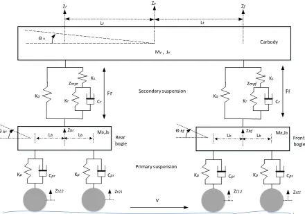
[image:62.595.93.534.76.385.2]V Ka Kr Ks Cr Zmpr Ka Kr Ks Cr Zmpf Secondary suspension Primary suspension
Figure 4.1: Schematic representation of the airspring in vertical secondary suspension of the railway vehicle
The governing equations of motion for the railway vehicle are listed below: The equation of vehicle motion into the vertical direction is:
𝑧̈𝑣 =𝑚1
𝑣 [−𝑘𝑎(𝑧𝑓− 𝑧𝑏𝑓) − 𝑘𝑠(𝑧𝑓− 𝑧𝑚𝑝𝑓) − 𝑘𝑎(𝑧𝑟− 𝑧𝑏𝑟)−𝑘𝑠(𝑧𝑟− 𝑧𝑚𝑝𝑟) ]…… (4.1)
The equation of vehicle motion for pitch is:
𝜃̈𝑣 = 𝐽1
𝑣 [−𝑘𝑎𝑙𝑡(𝑧𝑓− 𝑧𝑏𝑓) − 𝑘𝑠𝑙𝑡(𝑧𝑓− 𝑧𝑚𝑝𝑓) + 𝑘𝑎𝑙𝑡(𝑧𝑟− 𝑧𝑏𝑟)+𝑘𝑠𝑙𝑡(𝑧𝑟−
𝑧𝑚𝑝𝑟)]……….. (4.2)
From Figure 4.1, the displacements at the front and rear secondary suspension are:
𝑧𝑓 = 𝑧𝑣+ 𝑙𝑡 . sin (𝜃𝑣)
![Figure 1.1: Force – velocity diagram for semi-active damper[15]](https://thumb-us.123doks.com/thumbv2/123dok_us/8676759.873669/22.595.99.506.76.378/figure-force-velocity-diagram-for-semi-active-damper.webp)
![Figure 5.2: Cross-section of typical MR fluid damper[104]](https://thumb-us.123doks.com/thumbv2/123dok_us/8676759.873669/94.595.182.450.69.319/figure-cross-section-typical-mr-fluid-damper.webp)
![Table 5.1:MR damper parameters[28]](https://thumb-us.123doks.com/thumbv2/123dok_us/8676759.873669/97.595.75.526.85.403/table-mr-damper-parameters.webp)