International Journal of Emerging Technology and Advanced Engineering
Website: www.ijetae.com (ISSN 2250-2459, ISO 9001:2008 Certified Journal, Volume 9, Issue 5, May 2019)
Transformer Health Monitoring Using IOT and LABVIEW
Taru Agarwal
1, Harpreet Singh
21M.Tech Scholar, Power Systems, 2HOD, EE, Institute of Engineering and Technology, Alwar, India
Abstract—In this paper real time online health monitoring
of transformer is done. The transformer temperature, voltage level and load current is monitored on LABVIEW software and also on IOT platform ThingSpeak. The hardware framework mainly constitutes LCD, WiFi Module ESP8266, Arduino ATMEGA328 Microcontroller and sensors. For transformer protection relays are used. The IOT stage and LABVIEW contain data about the variation from the norm as per some predefined guidelines modified in the microcontroller for the protection of the transformer.
Keywords—Transformer, Arduino, IOT, LABVIEW, ThingSpeak
I. INTRODUCTION
Transformer acts as a backbone/heart of any electrical system. It is the only component through which we provide power supply to electrical system. All the equipments in the power system are connected to it. It is an integral part of the power system. Healthy transformer ensures the proper flow of electrical power and avoids any disturbance in the electrical system. Real time monitoring of transformers is very essential so as to detect faulty conditions and for protection using relays or other methods.
Proper Monitoring also ensures the safety to the manpower involved by avoiding any accident in the industry. Transformers are highly costly and its manufacturing takes lot of time so it cannot be stored as spare in industry and that is why its monitoring is important.
In this paper we have developed a hardware which is interfaced to computer and internet for real time online monitoring the transformer three parameters such as temperature, voltage and load current. Its controlling is done using Arduino ATMEGA328 microcontroller instead of 8051 microcontroller which have better and accurate features. The results are displayed on LCD (16x2) using interfacing of temperature, voltage and current sensors. For online monitoring WiFi Modem is used and parameters can be viewed on computer using IOT & LABVIEW Software. DC motor is used as load to one of the transformer and its protection using relay is shown for undervoltage condition. Fan is also provided to cool the transformers if the temperature rises above decided value.
II. PROBLEM STATEMENT
Transformers are among the most bland & costly bit of gear of the transmission & distribution framework. Customary monitoring health state of transformer not exclusively is sparing likewise adds to expanded unwavering quality. Numerous monitoring frameworks utilize control transporter correspondence to send information, yet the power bearer correspondence has a few burdens: genuine recurrence obstruction, with the expansion in separate the flag lessening genuine, stack changes realized vast electrical clamor. So if utilize control transporter correspondence to send information, the constant information transmission, unwavering quality can't be ensured. As indicated by the above necessities, we require a distribution transformer ongoing monitoring framework to recognize every working parameter activity, and send to the monitoring focus in time. It prompts internet monitoring of key operational parameters of distribution transformers which can give valuable data about the health of transformers which will push the utilities to ideally utilize their transformers and keep the advantage in activity for a more drawn out period. This will recognize issues before any genuine disappointment which prompts a noteworthy cost investment funds and more prominent unwavering quality. Far reaching utilization of portable systems and Wi-Fi gadgets such modems and their diminishing expenses have made them alluring choices for voice media as well as for other wide territory arrange application.
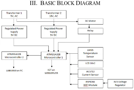
[image:1.612.336.552.548.693.2]III. BASIC BLOCK DIAGRAM
International Journal of Emerging Technology and Advanced Engineering
Website: www.ijetae.com (ISSN 2250-2459, ISO 9001:2008 Certified Journal, Volume 9, Issue 5, May 2019)
Fig. 1 shows the implemented block diagram of the Arduino based Transformer Health Monitoring Kit.
A brief discussion of the components is given below: a) Potential Transformer
A transformer is a static electrical device that transfers electrical energy between two or more circuits without a change in frequency. PTs are generally used to measure high voltage applications. It acts as a voltage sensor which senses the system voltage. The bridge rectifier converts the AC voltage into DC voltage and is connected to analog pic of microcontroller. Also potentiometer is used for calibration to change the supply voltage and produce under voltage and over voltage fault in the power system.
Here 3 Centre Tapped 9V, 1A rating Potential Transformers are used. One is used as Power Supply, 220V/9V. And the other two transformers are used for monitoring and the comparative results are shown. One is transferring 18V and other 9V. External Load (DC Motor) is connected through 9V transformer
b) LCD
Here 16x2 LCD is used. 16x2 LCD has 2 horizontal line which comprising a space of 16 displaying character. LCD have Eight (8) information pins, VCC (Apply 5v here), GND (Ground this pin), RS (Register select), RW (read - compose), EN (Enable), V0 (Set alphanumeric show differentiate).
8-Data pins convey 8-bit order or information to be shown from an outer unit, for example, a microcontroller.
LCD is used to display the transformer parameters such as temperature, voltage and load current. Arduino board serially communicates with LCD to display results.
c) LM35 Temperature Sensor
The LM35 series are precision integrated-circuit temperature sensors, whose output voltage is linearly proportional to the Celsius (Centigrade) temperature. It possesses low self-heating and does not cause more than 0.1 °C temperature rise in still air. The operating
temperature range is from -55°C to 150°C. The output
voltage varies by 10mV in response to every oC rise/fall in ambient temperature, i.e., its scale factor is 0.01V/ oC. d) Relay
A relay is an electromagnetic switch operated by a relatively small electric current that can turn on or off a much larger electric current.
Two relays are used. Both the relays are interfaced with microcontroller.
One relay is used to operate Fan in case the temperature of the transformers rises above 40oC and other is used for the protection of Induction Motor. Both are operating at 5V DC and can withstand 10A operating load.
e) Arduino Uno ATMEGA328
Arduino board has Microcontroller ATMega328. Its Clock Speed is 16MHz. It has Analog Input pins 6. It has Digital universally useful information yield pins 14 (6 pins are accommodated PWM voltage). Information voltage is 6-20V Working Voltage is 5V.
This microcontroller is predicated on the AT mega 328. There square measure aggregate of twenty pins (0-19) out of that about six square measure simple information sources which may even be utilized as broadly useful pins, an artistic resonator of recurrence 16MHz, A USB affiliation, an impact jack and a push. It contains everything required to help a microcontroller.
[image:2.612.325.570.381.558.2]This board channels serial communication through USB and appears as a arbitary port to software on PC. Fig. 2 shows the Arduino Board diagram.
Fig. 2 Arduino Uno ATMEGA328
f) WiFi Module ESP8266
International Journal of Emerging Technology and Advanced Engineering
Website: www.ijetae.com (ISSN 2250-2459, ISO 9001:2008 Certified Journal, Volume 9, Issue 5, May 2019)
g) ACS712 Current Sensor
Precise Current value can be obtained using this sensor. This sensor yields a little voltage that increment with current moving through the sensor. Operating Voltage is 5V DC and 5A can be measured.
h) LABVIEW
LABVIEW stands for Laboratory Virtual Instrument Engineering Workbench. In this program is created using a graphical notation unlike programming languages like C, C++, or Java, in which we program with text.
[image:3.612.324.572.264.501.2]It uses a graphical programming language called “G”. The programs are coded in a pictorial form called a block diagram. Fig. 3 shows the Front Panel of LABVIEW.
Fig. 3 Front Panel of LABVIEW
Fig. 4 shows the Block Diagram Panel of LABVIEW showing implemented block diagram of the model.
Fig. 4 Implemented Block Diagram Panel of LABVIEW
i) IOT
IOT is an extension of Internet connectivity into physical devices and everyday objects. The devices can communicate and interact over internet, and can be remotely monitored and controlled.
ThingSpeak is an open source IOT application and API (Application Programming Interface) to store and retrieve data from things using the HTTP protocol over the internet. ThingSpeak uses numerical computing software MATLAB from Mathworks to analyse and visualise uploaded data without requiring the purchase of licence.
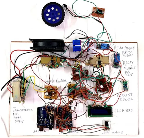
IV.PROJECT HARDWARE
Below figure is the hardware used for Health Monitoring of Transformer.
Fig. 5 Implementation Layout of Transformer Health Monitoring System
V. RESULT 1) LCD RESULTS
Temperature of Transformer 1, T1 = 29oC Temperature of Transformer 2, T2 = 24oC Voltage of Transformer 1, V1 = 10V Voltage of Transformer 2, V2 = 22V
Fig. 6 shows the results which are displayed on LCD.
[image:3.612.47.290.303.430.2] [image:3.612.47.287.458.623.2]International Journal of Emerging Technology and Advanced Engineering
Website: www.ijetae.com (ISSN 2250-2459, ISO 9001:2008 Certified Journal, Volume 9, Issue 5, May 2019)
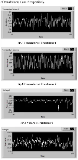
2) LABVIEW RESULTS
[image:4.612.346.536.108.700.2]The LABVIEW results are displayed on front panel of LABVIEW. The average value shows the final results.
Fig 7, 8, 9, 10 shows the temperatures and voltage levels of transformers 1 and 2 respectively.
Fig. 7 Temperature of Transformer 1
Fig. 8 Temperature of Transformer 2
[image:4.612.45.538.127.757.2]Fig. 9 Voltage of Transformer 1
Fig. 10 Voltage of Transformer 2
3) ThingSpeak RESULTS
[image:4.612.46.304.183.711.2]Fig. 11 Temperature of Transformer 1
Fig. 12 Temperature of Transformer 2
Fig. 13 Voltage of Transformer 1
[image:4.612.349.534.413.694.2]International Journal of Emerging Technology and Advanced Engineering
[image:5.612.79.261.134.258.2]Website: www.ijetae.com (ISSN 2250-2459, ISO 9001:2008 Certified Journal, Volume 9, Issue 5, May 2019)
Fig. 15 Load Current of Transformer 1
VI. CONCLUSION &FUTURE SCOPE
Hence we conclude prototype was working fine on Internet and LABVIEW. It is useful for taking values instantly. The advantages of our proposed system are:
1.Less costly and is simple to design and code 2.Accurate results can be obtained
3.User can take data from anywhere in the world using internet
4.Flexible and user friendly 5.Reliable and stable
In future work we can add more transformer units. Also we can add sensor for overvoltage protection. Also IOT based controlling can be done using WiFi SOC to operate relays for the protection of motors or any other load.
REFERENCES
[1] Sushant Mahadik, Shubham Paithankar, Chitesh Nagarikar, “GSM Based Transformer Healthcare Monitoring and Protection”, © 2019 IJSRSET, Volume 5, Issue 7
[2] D.Sarathkumar, Uvaraj.M, Kabilesh Kumar C V, Kalaiselvi A, “Real Time Transformer Health Monitoring System using IOT”, International Journal of AdvancedResearch in Science, Engineering and Technology, Vol. 5, Issue 11, November 2018
[3] V.Manopriya, Dr.G.Prakash, “ Design And Implementation Of Real Time Transformer Health Monitoring System Using Gsm Technology”, International Research Journal In Advanced Engineering And Technology Volume 4, Issue 03, June 2018 [4] Mohammad Riyaz, Ravi Agarwal, Sanjiv Kumar, “Analysis of
Distribution Transformer Health Monitoring and Protection using Arduino”, International Journal of Innovative Research in Science, Engineering and Technology, Vol. 7, Issue 6, June 2018
[5] K.Sridhar, M.Assarudeen, J.Ranjith Kumar, E.Sarathbabu, “Transformer Health Monitoring and Control Through Arduino”, International Journal of Advance Engineering and Research Development Volume 5, Issue 04, April -2018
[6] Deepraj Duttachowdhury1, Vivek Patil2, Arya Parab3, Raj Patel4 Karuna Nikum,” Transformer Monitoring and Control Using Iot”, International Conference on Innovative and Advanced Technologies in Engineering (March-2018)
[7] V. Sanjeeya E. Ramyashankari M. Sakthi Kannan A. Vidhya, “Real Time Transformer Health Monitoring System using IOT Technology”, Volume 4 | Issue 09 | March 2018
[8] Mr. S. Mudakannavar1, Swapnil Linge2, Avinash Mali3, Vishal Shinde4, Swapnil Dhonukshe5, “ IOT Based Real Time Monitoring Of Distribution Transformer”, International Journal of Recent Trends in Engineering & Research (IJRTER) Volume 04, Issue 03; March- 2018
[9] Akshay R. Thakare1, Sneha S. Yadaw2, Pushkar I. Vasekar3, Vanita M. Solanke4, “ Protection and Monitoring Of Transformer Using Arduino” International Journal for Research in Applied Science & Engineering Technology (IJRASET), Volume 6 Issue II, February 2018
[10] R.Salini, R.Keerthana, R.Archana, K.Pooja, “ Real Time Transformer Health Measuring System using IOT Technology”, International Journal of Engineering Trends and Technology (IJETT) – Volume 56 Number 2 February2018