MEDICAL CENTER SYSTEM
OPERATIONS MANUAL
(JAVA Edition)
functions, or features, at any time, without notice.
NEC America, Inc. has prepared this document for the exclusive use of its employees and customers. The information contained herein is the property of NEC America, Inc. and shall not be reproduced
without prior written approval from NEC America, Inc.
NEAX and Dtermare registered trademarks of NEC Corporation.
© 2000 NEC America, Inc.
Printed in the USA
All other brand or product names are or may be trademarks or registered trademarks of, and are used to identify products or
services of, their respective owners.
MS-DOS, Microsoft, Windows, and Windows NT are registered trademarks of Microsoft Corporation. Microsoft Windows 95 and
Medical Center System Operations Manual - JAVA Edition CONTENTS
TABLE OF CONTENTS
Page
Chapter 1 - INTRODUCTION . . . 1
What is Medical Center System?. . . 1
Telnet and JAVA Interfaces. . . 2
Operator Functions . . . 2
Supervisor Functions . . . 2
Password Security . . . 3
How to Use This Manual . . . . 4
Manual Organization . . . 4
Chapter Layout . . . 5
Option/Command Selection . . . 6
Procedures . . . 7
General Key Use . . . 7
Chapter 2 - SERVER INSTALLATION . . . 9
Introduction . . . 9
Hardware Installation . . . 11
Number Attendant Station . . . 11
Software Installation . . . 12
Step 1: Superuser/ Root Password . . . 12
Step 2: MCS Login Names . . . 13
Step 3: MCS Installation Processing . . . 13
Step 4: Informix Database Installation . . . 14
Step 5: Jmcmp Server Software Installation. . . 14
Step 6: Java Server/Client Component Installation . . . 18
Application Configuration. . . 19
Step 1: Application Characteristics . . . 20
Step 2: Monitor Configuration. . . 21
Step 3: Server Configuration . . . 24
Step 4: Recluster Primary Configuration . . . 27
Step 5: Host Statistics Primary Configuration. . . 27
Step 6: Cleaner Primary Configuration. . . 28
Step 7: Java Services Primary Configuration . . . 29
Step 8: Mcs_Dbclean Control Options . . . 30
Step 9: Mcs_Recluster Control Options . . . 30
Step 10: Mcs_Host_ Statistics Control Options . . . 30
Database Requirements . . . 32
MCSCFG Database Information. . . 32
MAT Assignments . . . 34
Attendant Station Preparation . . . 35
To Configure Attendant Stations . . . 35
Chapter 3 - JAVA MCS CLIENT INSTALLATION . . . 37
Overview . . . 37
Page
Screen Format. . . 44
Selecting Operator Functions . . . 45
Status Area. . . 46
Source Area . . . . 47
Destination Area . . . 49
Directory Assistance . . . 50
General Process. . . 50
Hot Key. . . 51
Directory Information . . . 51
Special Destinations . . . 52
Expanded Display. . . 52
Type of Transfer . . . 52
Operator Transfer . . . 52
Transfer Failures . . . 53
Off-Line Mode. . . 53
Key Function Summary . . . 53
Procedure . . . 54
Call Park . . . 55
General Process. . . 55
Park Recall . . . 56
Cancel and Exit . . . 56
Procedure . . . 56
Parked Call Retrieval. . . 57
General Process. . . 57
Retrieve from Idle Screen. . . 57
Park Call Abandon . . . 58
Cancel and Exit . . . 58
Procedure . . . 58
Beeper . . . 59
General Process. . . 59
Procedure . . . 60
Redial . . . 61
General Process. . . 61
Procedure . . . 61
Emergency . . . 62
General Process. . . 62
Supervisor Equipment . . . 63
Supervisor Capability . . . 63
Expanded Display. . . 63
Procedure . . . 63
Chapter 5 - JAVA OPERATOR FUNCTIONS . . . 65
Login . . . 65
Screen Format. . . 66
Selecting Operator Functions . . . 68
Status Area. . . 68
Source Area . . . . 70
Destination Area . . . 70
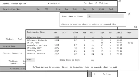
Directory Assistance . . . 72
Medical Center System Operations Manual - JAVA Edition CONTENTS
Page
Directory Information . . . 73
Special Destinations . . . 74
Expanded Display. . . 74
Type of Transfer . . . 74
Operator Transfer . . . 74
Transfer Failures. . . 75
Off-Line Mode . . . 75
Key Function Summary . . . 75
Make a Call . . . 76
Transfer a Call . . . 76
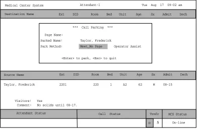
Park a Call . . . 77
Park Recall . . . 78
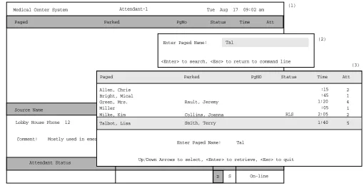
Retrieve Parked Call . . . 80
Retrieve from Idle Screen. . . 81
Park Call Abandon . . . 81
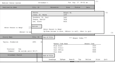
Call a Beeper . . . 82
Redial . . . 83
Chapter 6 - DATABASE ADMINISTRATION . . . 85
Introduction . . . 85
Types of Database Records . . . 85
Procedures . . . . 86
Extension Assignments . . . 86
View Command . . . 86
Menu Access . . . 86
Screen Samples . . . 87
Database Entry and Exit Procedure . . . 87
Database Procedures . . . . 88
Add a Record / Admit a Patient . . . 88
Delete a Record/ Discharge a Patient . . . 90
Modify a Record . . . 92
View Database Records . . . 94
Print Database Records . . . 96
Database Record Descriptions . . . 97
Patients. . . 97
Physicians . . . 98
Employees . . . . 99
Attendant Stations . . . 100
Other Internal Extensions . . . 100
Tests / Procedures . . . 101
External Numbers . . . 101
Trunk Numbers . . . 102
Beeper Codes. . . 102
Emergencies. . . 102
Page
PBX Restriction Classes. . . 107
Other Affected Options . . . 107
Procedure . . . 108
Extension Maintenance . . . 109
Internal Extension Assignments . . . 109
Pop-up Window Information . . . 109
Empty Fields. . . 110
Range Values . . . 110
Common Procedure . . . 110
View Command . . . 110
Menu Access . . . 110
Procedure . . . 111
Add an Extension . . . 112
Assignment Sequence . . . 112
Extension Record Descriptions . . . 112
Procedure . . . 114
Delete an Extension . . . 115
Procedure . . . 115
Modify an Extension . . . 116
Procedure . . . 116
View Extension Records . . . 118
Procedure . . . 118
Print Extension Records . . . 120
Procedure . . . 120
Patient DID Numbers. . . 121
Transfers . . . 121
DID Number Status . . . 121
“Stamped” Notation . . . 122
Procedure . . . 122
Add Patient DID Numbers . . . 123
Delete Patient DID Numbers . . . 124
View Patient DID Numbers. . . 125
Print Patient DID Numbers . . . 127
Outstanding RSC Requests . . . 128
Outstanding RSC Database . . . 128
Procedure . . . 128
Resend an RSC Request . . . 129
Delete an RSC Request . . . 130
View Outstanding RSC Requests. . . 131
Print Outstanding RSC Requests . . . 133
Outstanding DID Requests . . . 134
Outstanding DID Database. . . 134
Display Fields . . . 134
Procedure . . . 135
Resend a DID Request. . . 136
Delete a DID Request. . . 137
View Outstanding DID Requests . . . 138
Print Outstanding DID Requests . . . 140
Medical Center System Operations Manual - JAVA Edition CONTENTS
Page
Displayed Parameters . . . 141
Procedure . . . 142
Chapter 9 - LOGIN NAME MAINTENANCE. . . 145
Option Overview . . . 145
Search Function . . . 146
View Function . . . 146
Procedure . . . 146
Chapter 10 - SUPERVISOR REPORTS . . . 149
Date-Stamped Files . . . 149
Operator Statistics . . . 150
Procedure . . . 151
Chapter 11 - PROCESS AND ERROR MESSAGES . . . 153
Chapter 12 - PLATFORM MANAGEMENT . . . 165
Introduction to Platform Management . . . 165
Menu Options . . . 165
Sequence of Option Use . . . 166
Warning . . . 166
Procedure . . . 166
Backup Database Option. . . 167
Delay . . . 167
When to Use. . . 167
Procedure . . . 168
Create Database Option . . . 169
When to Use. . . 169
Procedure . . . 169
Drop Database Option . . . 170
Sequence . . . 170
Procedure . . . 170
Make Database Indexes Option . . . 171
Sequence . . . 171
Procedure . . . 171
Erase Database Indexes Option . . . 172
Sequence . . . 172
Procedure . . . 172
Rebuild Database Indexes Option . . . 173
When to Use. . . 173
Procedure . . . 173
Set Menu Colors Option . . . 174
General Process . . . 174
Representative Screens . . . 175
Page
FLF/RCF Download to PBX Option . . . 180
Warning . . . 180
DID Numbers . . . 180
Effect on Database . . . 180
Procedure . . . 180
Chapter 13 - HOST INTERFACE ADMINISTRATION . . . 181
Introduction . . . 181
Interface Status . . . 181
Version . . . 181
Menu Options . . . 182
Procedure . . . 182
Log File Options . . . 183
Contents . . . 183
Real-Time Display . . . 183
Hard Copy Print . . . 183
View Log File Procedure . . . 184
Erase Log File Procedure. . . 184
Initialization and Termination Options . . . 185
Initialization Procedure . . . 185
Termination Procedure . . . 185
Configuration Option . . . 186
Contents . . . 186
Procedure . . . 187
Statistics Option. . . 189
Display Contents . . . 189
Real-Time Display . . . 189
Hardcopy Print . . . 189
Appendix A - BEEPER INTERFACE . . . 1
Overview . . . 1
Database Fields . . . . 1
Architecture . . . 2
Using the Beeper Interface . . . 4
Local Pager Process . . . 6
Dial Number Process . . . 8
Error and User Interface Messages . . . 9
Interface Configuration . . . 10
Medical Center System Operations Manual - JAVA Edition FIGURES
LIST OF FIGURES
Figure Title Page
1-1 Medical Center System . . . 1
2-1 Super User Root . . . 12
2-2 Example Install Screens . . . 12
2-3 MCS Installation Processing . . . 13
2-4 Informix Setup . . . 14
2-5 Jmcmp Pre-Install - 1st Install . . . 14
2-6 Jmcmp Pre-Install - Install Options . . . 15
2-7 Jmcmp Pre-Install - Upgrade Option . . . 15
2-8 Jmcmp Pre-Install - Overwrite Option . . . 15
2-9 Jmcmp Installation - Access to Data . . . 16
2-10 Jmcmp Installation - Initial Installation. . . 16
2-11 Jmcmp Installation - Upgrade Installation . . . 16
2-12 Jmcmp Installation - Overwrite Installation . . . 17
2-13 Jmcmp Installation - Overwrite APM Application Configuration . . . 17
2-14 Allowable Client Connections Description. . . 17
2-15 Allowable Client Connections Configuration File. . . 18
2-16 Jmcmp Installation - Installation Complete . . . 18
2-17 MCS Login Screen . . . 35
3-1 NEC UNIX OAI Applications Installation Page . . . 37
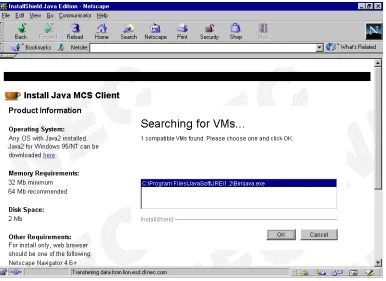
3-2 Java Virtual Machine option dialog box. . . 38
3-3 Searching for VMs dialog box . . . 39
3-4 Installing Application progress indicator . . . 40
3-5 Welcome dialog box . . . 40
3-6 Installing Files progress indicator . . . 41
3-7 Installation Complete dialog box . . . 41
4-1 Password Entry . . . 43
4-2 Screen Format. . . 44
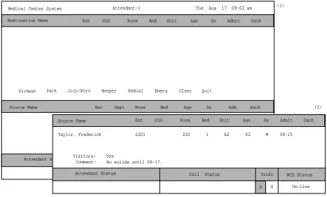
4-3 Operator Screen . . . 45
4-4 Patient Caller. . . 47
4-5 Internal Staff or Non-Patient Caller . . . 48
4-6 Incoming From an External Trunk . . . 48
4-7 Directory Assistance . . . 50
4-8 Call Park Function . . . 55
4-9 Parked Call Retrieval. . . 57
4-10 Beeper Function . . . 59
4-11 Redial Function . . . 61
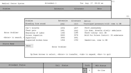
4-12 Emergency Function . . . 62
5-1 Password Entry Screen. . . 65
5-2 JAVA MCS Main Screen . . . 66
5-3 Operator Screen - Status Area . . . 68
5-4 Operator Screen - Call Source Area . . . 70
Figure Title Page
5-10 Parked Call Retrieval Window. . . 80
5-11 Beeper Function Window . . . 82
6-1 Database Administration . . . 85
6-2 Record Field and Command Line Samples . . . 87
6-3 Add a Record/Admit a Patient . . . 88
6-4 Delete a Record/Discharge a Patient . . . 90
6-5 Modify a Record . . . 92
6-6 View Database Records . . . 94
6-7 Print Database Records . . . 96
7-1 System Administration . . . 105
7-2 Restriction Class Descriptions . . . 107
7-3 Extension Maintenance. . . 109
7-4 Record Field and Command Line Samples . . . .110
7-5 Add an Extension . . . .112
7-6 Delete an Extension . . . .115
7-7 Modify an Extension . . . .116
7-8 View Extension Records . . . .118
7-9 Print Extension Records . . . 120
7-10 Patient DID Numbers . . . 121
7-11 Add Patient DID Numbers . . . 123
7-12 Delete Patient DID Numbers . . . 124
7-13 View Patient DID Numbers . . . 125
7-14 Print Patient DID Numbers . . . 127
7-15 Outstanding RSC Requests . . . 128
7-16 Resend Outstanding RSC Request . . . 129
7-17 Delete Outstanding RSC Request . . . 130
7-18 View Outstanding RSC Requests . . . 131
7-19 Print Outstanding RSC Requests . . . 133
7-20 Outstanding DID Requests . . . 134
7-21 Resend Outstanding DID Request . . . 136
7-22 Delete Outstanding DID Request . . . 137
7-23 View Outstanding DID Requests. . . 138
7-24 Print Outstanding DID Requests . . . 140
8-1 Platform Management. . . 141
9-1 Login Name Maintenance . . . 145
9-2 View Operator Login Names . . . 148
10-1 Supervisor Reports . . . 149
12-1 Platform Management. . . 165
12-2 Backup Database . . . 167
12-3 Create Database . . . 169
12-4 Drop Database . . . 170
12-5 Make Database Indexes . . . 171
12-6 Erase MCS Database Indexes . . . 172
12-7 Rebuild Database Indexes . . . 173
12-8 Set Menu Colors . . . 174
12-9 Database Table Record Count . . . 178
Medical Center System Operations Manual - JAVA Edition FIGURES
Figure Title Page
12-11 FLF/RCF Download to PBX . . . 180
13-1 Host Interface Administration . . . 181
13-2 Interface Log File. . . 183
13-3 Interface Initialization/Termination . . . 185
13-4 Interface Configuration File . . . 186
13-5 Interface Statistics . . . 189
A-1 Beeper Connectivity . . . 2
A-2 Beeper Software Interface. . . 3
A-3 Console Screen. . . 4
A-4 Database Beeper Number Display . . . 5
A-5 Local Pager Message Screen . . . 6
A-6 Pager Message Error . . . 7
A-7 Beeper Codes Screen . . . 8
A-8 Beeper Interface Administration Menu . . . 10
A-9 Configuration Menu . . . 11
A-10 Configuration Files . . . 11
A-11 Misc Parameters Window . . . 12
A-12 Port Parameters Window . . . 13
A-13 Timer Parameters Window . . . 13
A-14 View Log File Menu. . . 14
Medical Center System Operations Manual - JAVA Edition INTRODUCTION
Chapter 1
INTRODUCTION
What is Medical Center System?
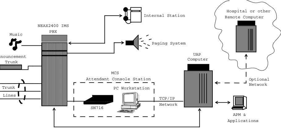
The Medical Center System (MCS) provides enhanced operator functions and call handling for a medical center environment. MCS combines the NEC Advanced Attendant Console with a general purpose computer equipped with a UNIX System V operating environment, the NEC Applications Manager support platform, and a comprehensive package of software components.
MCS operates with a SN716 Attendant Console. The illustration below (Figure 1-1) shows the MCS components in a typical configuration:
Figure 1-1 Medical Center System
MCS provides enhanced functionality by using the NEC Open Applications Interface (OAI) communication pathway between the UAP computer and the NEAX2400 PBX system. The PBX and UAP utilize standard TCP/IP network media for communication allowing flexible deployment options.
The MCS JAVA Edition (MCS-JE) includes a JAVA based client Graphical User Interface (GUI) that can be installed on any PC Workstation that supports Sun Microsystems JAVA Virtual Machine (JVM) Release 1.1.7 or greater. The MCS-JE client installation provides a compatible JVM runtime for Microsoft Windows 9x.
MCS-JE also supports previous MCS customers that do not use PC Workstations to connect to the MCS UAP. The MCS-JE software components can be configured
Computer Paging System
Internal Station
OAI Connection (TCP/IP Network)
APM & NEAX2400 IMS
Trunk Announcement
Music
MCS
Lines
Attendant Console Station
Applications Remote Computer
Trunk
Hospital or other
UAP
TCP/IP Network
Optional Network
SN716 PBX
Telnet and JAVA
Interfaces
The MCS-JE supports both JAVA GUI and the character based Telnet terminal session interfaces. The JAVA GUI is available for operator features and functions. Database administration between the PC Workstation (client) and the MCS UAP uses the character based Telnet interface.
To use the character based interface, a third-party terminal emulation program that supports the Telnet session protocols must be installed on the PC Workstation. The standard MS Windows Telnet program is NOT recommended as it does not adequately support colors and cursor positioning. Other commercial terminal emulation programs that support Telnet sessions such as PowerTerm or SCO TermVision are suggested.
Operator
Functions
MCS provides up to 16 medical center operators with an on-screen display of caller information and an interactive screen for caller assistance using the functions:
• Directory Assistance – Provides information retrieval from a computer
database and directs incoming calls to their destinations. The database contains patient, staff, and other information that is designed for either stand-alone use or for interactive transactions with a remote database server.
• Park/Page Retrieval – Allows the operator to transfer an incoming call to an
announcement trunk or to a monitored number for later retrieval.
• Beeper Connection – Displays a database listing of beeper assignments.
Automatic call placement and manual entry of message codes is supported. Alphanumeric beeper messaging is supported with an add-on beeper interface package.
• Redial Caller – Automatically attempts to reestablish connection with the most
previous internal extension.
• Emergency Response – Displays a database of emergency response teams and
agencies for operator selection, and automatically places the chosen call.
Supervisor
Functions
MCS provides supervisory functions using password security access for the management of the MCS resources used by MCS operator functions. The Supervisor may perform the following functions by accessing the menu items listed below:
• Database Administration – Add, delete, modify, view, and print the large
variety of database records that are required by MCS operator functions.
• System Administration – Make extension assignments, including the types of
restrictions that affect their use, and direct inward dialing numbers controlled by MCS.
• Configuration Management – Modify or print configuration parameters that
affect processing of time-outs and the Operator Functions display fields.
• Login Maintenance – Manage the MCS login and password security system as
Medical Center System Operations Manual - JAVA Edition INTRODUCTION
• Supervisor Reports – View and print statistical reports generated from
operator call processing activity.
Note: The initial release of MCS-JE does not support JAVA GUI interfaces for all su-pervisory functions. Where not supported, the Telnet session interface will be used.
In addition to these menu-driven capabilities, the supervisor can respond to an operator emergency alert by silently monitoring an ongoing conversation between a caller and an operator.
Password Security
The MCS menu system serves up to 16 operators and one supervisor. Operators can be configured with operator functions or with operator and database management capabilities. If operators are not configured for access to database functions, entering the operator password on the login screen automatically displays an Operator Functions screen.How to Use This Manual
Manual
Organization
This manual is organized around the MCS Main Menu illustrated in Chapter 3 for the Telnet interface and Chapter 4 for the JAVA GUI interface. The later chapters describe these Main Menu features and functions. Refer to the following chapters to install, configure, and operate MCS-JE:
• Chapter 2, “SERVER INSTALLATION”
• This chapter addresses the server hardware and software installation of MCS as well as the necessary configuration files, databases, and other data and equipment assignments that are required by MCS.
• Chapter 3, “JAVA MCS CLIENT INSTALLATION”
If using the JAVA GUI, this describes the procedure to install the MCS-JE JAVA GUI on a PC Workstation.
• Chapter 4, “TELNET OPERATOR FUNCTIONS”
This provides an illustrated reference and procedural guide to all of the functions provided to MCS operators using the Telnet protocol interface.
• Chapter 5, “JAVA OPERATOR FUNCTIONS”
This chapter provide an illustrated reference and procedural guide to all of the functions provided to MCS operators using the JAVA GUI.
• Chapter 6, “DATABASE ADMINISTRATION”
This chapter describes the procedures to manage the various types of database records used by MCS.
• Chapter 7, “SYSTEM ADMINISTRATION”
This describes phone equipment numbers (e.g., extensions and trunk numbers) and the necessary assignments associated to them.
• Chapter 8, “CONFIGURATION MANAGEMENT”
This chapter describes configuration parameters that affect MCS operation and that can be modified by the supervisor as necessary.
• Chapter 9, “LOGIN NAME MAINTENANCE”
This describes the procedures for a supervisor to manage the login name and password security system.
• Chapter 10, “SUPERVISOR REPORTS”
Medical Center System Operations Manual - JAVA Edition INTRODUCTION
• Chapter 11, “PROCESS AND ERROR MESSAGES”
This chapter presents an alphabetical list of the messages that might appear throughout MCS screen operations with a brief description of their meaning and recovery measures, if appropriate.
• Chapter 12, “PLATFORM MANAGEMENT”
This chapter provides illustrated instructions for performing various tasks in support of MCS functions, including backing up the database on tape, managing the database indexes, resetting the colors seen on the MCS screens, and displaying MCS records and terminal assignments.
• Chapter 13, “HOST INTERFACE ADMINISTRATION”
This chapter describes the options that are available for managing the communication interface between the MCS and the hospital information system, including log file access, initialization and termination of the interface, and configuration and statistical data.
• Appendix A, “BEEPER INTERFACE”
This appendix describes the features and basic operation of NEC’s MCS alphanumeric paging interface.
Chapter Layout
When using MCS, you can often choose a Main Menu option to display either a second-level menu of options (e.g., choose the System Administration option on the Main Menu to display the System Administration menu) or a new series of commands (e.g., Add, Delete, Modify). The chapters in this manual follow the same organization in that each second-level menu option or command is presented as a separate section.
Each multi-level chapter begins with an overview that describes the entire chapter and the options discussed within the chapter. Each section includes an illustration of the screen(s) or window(s) associated with the procedure, information related to performance of the procedure, and step-by-step instructions.
Some graphics illustrate the progression among a group of related screens.
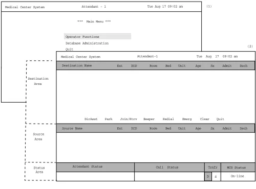
Medical Center System Supervisor Tue Aug 17 09:02 am
*** Main Menu ***
Database Administration System Administration Operator Functions
*** MCS System Administration ***
RSC DEscriptions Extension Maintenance Patient DID Numbers
*** Extension Maintenance ***
(3) (1)
(2)
The numbers in parentheses beside each screen graphic represent the number of the screen in the progression. These numbers are referenced in the procedural instructions, where applicable, to help you associate the action with the appropriate screen. In the illustration above, the Extension Main ten ace screen (3) displays after you select System Administration from the Main Menu (1) and Extension Maintenance from the MCS System Administration screen (2).
Option/Command
Selection
Medical Center System Operations Manual - JAVA Edition INTRODUCTION
Procedures
Each section includes step-by-step instructions on how to select and move to the required screen and how to perform the available actions. The procedures are presented in a two-column layout. The left column contains the action to be taken. The right column contains the results of that action. Where there are field entries to be made on the screen, this manual provides field names in the left column and corresponding field definitions in the right column.
General Key Use
Throughout MCS, the following keys generally perform the actions described below.
Note: Clear notation is made wherever other key or key combinations apply or these do not.
Enter – Accepts a selection or field entry.
Esc – Generally exits the current screen or action to the last screen or action.
Arrow keys – Move the cursor in the direction shown.
Space bar – Selects an option when more than one is available in a field; serves to toggle among scrolled or side-by-side options in a field.
Backspace – Erases any data in a field.
Tab – Expands a data record to expose more information or provide other options that can be selected.
Action Result
On the Main Menu, type s to select the System Administration option. (1)
The System Administration menu displays. (2)
On the System Administration menu, type e to select the Extension
Maintenance option.
Medical Center System Operations Manual - JAVA Edition SERVER INSTALLATION
Chapter 2
SERVER INSTALLATION
Introduction
This chapter provides a step-by-step description of the installation and setup of Medical Center System (MCS). The following steps must be taken before MCS can be installed:
1. The OAI/APM system must be installed on the SCO UNIX system.
2. The Informix Dynamic Server (IDS) Workgroup Edition Version 7.30 must be installed on the SCO UNIX system.
Note: A system obtained through NEC CNG Division will normally have been precon-figured with these requirements. If reinstalling or upgrading a system, the install-er should contact NEC to obtain the system staging procedures.
The installation and setup of MCS involves the following procedure. Perform the installation in this sequence and refer to the listed sections for detailed instructions:
1. Hardware Installation on page 11
Each attendant station consists of an NEC Advanced Attendant Console and a CRT. This section presents the attendant setup for each station and discusses how the hardware configurations are used to determine software characteristics.
2. Software Installation on page 12
This section discusses installation and configuration of the MCS software components of the UAP.
3. Application Configuration on page 19
MCS is internally supported by the Applications Manager (APM) and must therefore be set up in the APM environment. This section presents a detailed description of the required setup. Use the instructions provided in the APM Operations Manual to make the entries contained in this section.
4. Database Requirements on page 32
MCS provides two default APM databases that are loaded during software installation. One of these databases can be changed through the APM Database Administration option. This section defines the fields and entries in this database. Use the instructions provided in the APM Operations Manual to make any required changes to the database presented in this section.
5. MAT Assignments on page 34
Specific data settings must be assigned at the NEAX2400 Maintenance Administration Terminal (MAT) before MCS will function. This section specifies the necessary commands and the values to which they are to be set.
6. Attendant Station Preparation on page 35
7. Extension Installation
After the installation is performed as outlined in Steps 1 through 6, the extensions must be added to the Informix database. Each extension is assigned through the Extension Maintenance option, entered from the System Administration option on the MCS Main Menu.
Note: In some cases, sequence is important in the assignment process. We recommend a re-view of Chapter 7, “SYSTEM ADMINISTRATION” before beginning these assign-ments.
Medical Center System Operations Manual - JAVA Edition SERVER INSTALLATION
Hardware Installation
The hardware configuration of each attendant station determines the software characteristics for the attendant configuration in JAVA MCS. Each MCS attendant station consists of an NEC Advanced Attendant Console and a PC Workstation, and each is identified by the following unique characteristics:
Attendant ID: An attendant console equipment number for each particular station ranging from 1 to 16.
Extension: A unique extension assigned to the attendant console on the PBX.
Number
Attendant
Station
Number each attendant station with a unique value between 1 and 16, and label each with its assigned Attendant ID. The easiest method is to make the station Attendant ID match the logical ID of each attendant console as it is assigned on the NEAX
Software Installation
This section discusses the installation of MCS software from the release media and describes the required MCS software configurations. Before beginning this section, be sure to install the UNIX operating system, including the raw partition required for Informix, and the Applications Manager platform. Refer to the instructions provided with each of these software packages for more information.
Installation of MCS software is initiated from the Applications Manager (APM) Platform Maintenance Main Menu. To display this menu, type the login apmadm at the UNIX prompt and press Enter. When prompted, type the assigned password and press Enter. Using instructions in the APM Operations Manual, select and implement the Installation of Applications/Packages option from this menu to load MCS software from release media. As the installation process executes, follow the steps described below as they correspond to the screen display, and make entries as indicated. Required input is shown in boldface type.
Step 1:
Superuser/
Root Password
Type the password for the root login and press Enter to continue. If you type an invalid password, the message “Error entering root password. Installation failed” displays, the installation cancels, and you must restart the installation.
Figure 2-1 Super User Root
After entering a valid root password, the MCS user account installation will quickly display several screens as the install process continues. Some example screens are shown below:
Figure 2-2 Example Install Screens MCS Installation
Installation requires Super User (root) privileges.
Password: <root password> <Enter>
NOTE: To re-run this script login as ‘apmadm’ get to ‘Unix’ and execute the following command ‘/oai/install/mcs.ins’.
su root:
Installing 16 mcs network users on SCO UNIX. User (mcs1) installed.
User (mcs2) installed. User (mcs3) installed. User (mcs4) installed.
Deleting password for user: mcs1
Last successful password change for mcs1: NEVER
Deleting password for user: mcs2
Medical Center System Operations Manual - JAVA Edition SERVER INSTALLATION
Step 2: MCS
Login Names
The mcs and mcsadm login names are installed with the same user ID. (The default is 4001.) Any change in the user ID value must be made for both login names, since they both use the same user ID value. Press Enter at each user ID prompt to accept the default value. A warning message displays when the 4001 user is being installed. Type ‘y’ and press Enter at the warning prompt and continue the installation. The
installation should default through this section. If another user is using the assigned ID, you will need to select another ID by adding one to the default until it can be assigned.
Step 3: MCS
Installation
Processing
The installation script performs several steps after you enter the login name. Information about these steps displays as they are performed. None of these steps require input. This process includes the following actions:
• Entering boot-up commands into UNIX boot-up sequence.
• Installing all remaining MCS files and directories as well as MCS host directories and executables.
• Entering MCS crontab information.
At the prompt, type ‘y’ and press Enter to continue the installation.
Figure 2-3 MCS Installation Processing
. . .
Installing MCS system boot sequence... mcs crontabs entries complete... Installing gettydefs entry for MCS.
Installing MCS directories and executables...
Step 4: Informix
Database
Installation
The figure below shows a normal execution of the Informix setup and includes the required input for each prompt. Type y and press Enter if this is the first time this installation is being performed.
The informix user must not have a password, as described in the APM Informix Installation section. If the informix user does have a password, this step will fail. Required input is shown in boldface type.
Figure 2-4 Informix Setup
The APM Main Menu displays. Select the Logout option from the Main Menu.
Step 5: Jmcmp
Server
Software
Installation
JMCMP Pre-Install
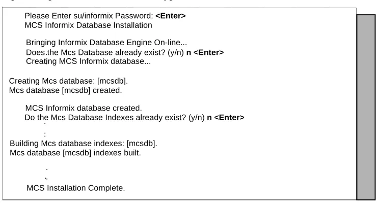
This installs the Java JMCMP server software. The JMCMP Pre-Install step of the installation checks for previous installed versions of JMCMP Server. If no previous versions exist, the following is displayed: Press Enter to continue.
Figure 2-5 Jmcmp Pre-Install - 1st Install
Please Enter su/informix Password: <Enter> MCS Informix Database Installation
. .
.
Creating Mcs database: [mcsdb]. Mcs database [mcsdb] created.
MCS Informix database created.
Do the Mcs Database Indexes already exist? (y/n) n <Enter>. ..
Building Mcs database indexes: [mcsdb]. Mcs database [mcsdb] indexes built.
. . .
MCS Installation Complete. Creating MCS Informix database...
Does the Mcs Database already exist? (y/n) n <Enter> Bringing Informix Database Engine On-line...
JMCMP Server Pre-Install
Checking the system configuration....
JMCMP Server Pre-Install Complete
Medical Center System Operations Manual - JAVA Edition SERVER INSTALLATION
Step 5: Jmcmp
Server
Software
Installation
(Cont)
However, if a previous version is detected, an option is given to either upgrade (leaving configured data alone), overwrite (completely overwrite all Jmcmp data), or abort the installation. Enter ‘u’, ‘o’, or ‘a’ to upgrade, overwrite, or abort the installation and then press Enter.
Figure 2-6 Jmcmp Pre-Install - Install Options
If the upgrade option is chosen, the following is displayed: Press Enter to continue
Figure 2-7 Jmcmp Pre-Install - Upgrade Option
If the overwrite option is chosen, the following is displayed: Press Enter to continue JMCMP Server Pre-Install
Checking the system configuration....
JMCMP Server Ver1.0 Currently Installed
Do you wish to upgrade, overwrite the existing JMCMP Server Installation or Abort? (u/o/a):
Saving Current JMCMP Server Applications and Configurations To insure access to data please login as root
Login: root Password:
Adjusting directory access ... Done.
JMCMP Server Pre-Install Complete
Press "Enter" to Continue Installation:
Overwriting Existing JMCMP Server Installation To insure access to data please login as root
Login: root Password:
Adjusting directory access ... Done.
JMCMP Server Pre-Install Complete
Step 5: Jmcmp
Server
Software
Installation
(Cont)
JMCMP Install
After the Pre-Install phase of installation, the following is displayed:
Figure 2-9 Jmcmp Installation - Access to Data
Enter the root password and press Enter to allow proper access to configuration data. If this is a first install of Jmcmp Server, the following is displayed:
Figure 2-10 Jmcmp Installation - Initial Installation
If the upgrade option is selected, as described in Figure 2-6, “Jmcmp Pre-Install - Install Options” on page 15, the Jmcmp Server application, the following is displayed:
Figure 2-11 Jmcmp Installation - Upgrade Installation
Pressing Enter installs the new applications, and then restores all configuration data from the previous installation. For the ‘Upgrade’ option, no other configuration is needed, and installation is complete.
Installation requires Super User (root) privileges.
NOTE: To re-run this script login as ’apmadm’ get to ’Unix’
and execute the following command ’/oai/install/jmcmpServer.ins’. su root
Password:
Initial JMCMP Server Install
Unpacking Install JMCMP Server Ver1.0.
Upgrading JMCMP Server Ver1.0 to Ver1.1
Unpacking Upgrade JMCMP Server Ver1.0 Installation Complete
Medical Center System Operations Manual - JAVA Edition SERVER INSTALLATION
Step 5: Jmcmp
Server
Software
Installation
(Cont)
If overwrite the existing installation is selected, the following is displayed:
Figure 2-12 Jmcmp Installation - Overwrite Installation
This installs the new applications, plus sets all configuration data to default values. If the Jmcmp Server was previously installed, the APM application “JmcmpConnServer” may already be configured. If so, the following is displayed:
Figure 2-13 Jmcmp Installation - Overwrite APM Application Configuration
To keep the same configuration parameters for the APM application
“JmcmpConnServer”, type ‘n’ and press Enter. To set the configuration parameters to default values, which must be modified later, type ‘y’and press Enter.
If this is an “Initial” installation, or if overwriting the existing installation, the allowable client connections to the Jmcmp Server must be defined. The following is displayed:
Overwriting JMCMP Server Ver1.0
Unpacking Install JMCMP Server Ver1.0.
Application "JmcmpConnServer" is already configured.
Do you wish to overwrite current configuration data with the new default data? (y/n)
JMCMP Server Connection ID Configuration
For each Java Client connection, an identifier must be defined. The identifier can be either:
(a) A fully qualified host name, or a hostname that can be resolved on the Server machine.
(e.g., "clientmachine.domain.com")
(b) The 32-bit IP address of the client machine. (e.g., "123.45.678.901")
(c) The 48-bit MAC address (Ethernet address) of the client’s Network Interface Card.
(e.g. 00:20:af:9c:5a:b3)
Do you wish to edit the JMCMP Server Connection ID configuration file at this time (vi editor) ? (y/n)
Step 5: Jmcmp
Server
Software
Installation
(Cont)
Entering ‘y’ and pressing Enter starts up the ‘vi’ editor, allowing modifications to the User Address Mapping File:
Figure 2-15 Allowable Client Connections Configuration File
For each client position, enter the hostname, IP address, or MAC address of the client machine. When the installation is complete, the following is displayed:
Figure 2-16 Jmcmp Installation - Installation Complete
Step 6: Java
Server/Client
Component
Installation
A Java software component must be installed on the server to enable communication with Java clients. This installation is initiated from the Applications Manager (APM) Platform Maintenance Main Menu. To display this menu, type the login apmadm at the UNIX prompt and press Enter. When prompted, type the assigned password and press Enter. Using instructions in the APM Operations Manual, select and implement the Installation of Applications/Packages option from this menu to load this software component from release media. When all release media has been loaded, the
installation of this component is complete. No further setup is required for this component.
#
# User Address Mapping File #
# In
# POS Use Address # --- --- 01 0 localhost 02 0
03 0 04 0 05 0 06 0 07 0 08 0 09 0 10 0 11 0 12 0 13 0 14 0 15 0 16 0
NEC America Inc JmcmpConnServer Ver1.0 Installation Wed - Aug 25, 1999
Installation Complete
Medical Center System Operations Manual - JAVA Edition SERVER INSTALLATION
Application Configuration
MCS is internally supported by the APM and must be configured in the APM environment.
MCS uses an autoconfiguration utility program to automatically configure some MCS settings for the APM platform. This program utility runs upon installation. If the utility runs successfully, specific adjustments can be made to the application parameters, depending on site requirements.
Note: If an error occurs during installation, you can try to run the autoconfig program again or you can enter the information into the APM manually using the information pro-vided in this chapter.
After the autoconfiguration utility has run successfully, the initialization time settings for the database processing applications must now be configured. Configuring these settings is described in three steps ( on page 28, Step 9: Mcs_Recluster Control Options on page 30, Step 10: Mcs_Host_ Statistics Control Options on page 30) in the following pages.
MCS is configured into the APM system using the Add command on the Application Configuration screen. To access the Application Configuration option, use the following steps:
1. Type the System Administrator password at the APM password screen.
2. Select the Application Configuration option from the System Administration menu.
This section contains the data that should be entered to the configuration file for MCS. The following components must be configured:
Monitor – Controls call parking and retrieval, restrictions, and DID number management.
Server – Controls source caller data displayed on the attendant consoles, directory assistance, and beeper functions. You may need to set up more than one server, depending on the server ratio and the number of attendants. (Refer to the Server Ratio section in Database Requirements on page 32.)
Recluster – Periodically reclusters Informix system tables for more efficient processing of the database. You must schedule this component under Control Options on the APM Operations Menu in order for it to function automatically.
Cleaner – Periodically cleans out any records of patients that have been discharged. It also makes available DID numbers that have been offered but not assigned to an admitted patient after a set amount of time. You must schedule this component under Control Options on the APM Operations Menu in order for it to function
automatically.
Java Services – Controls the Java graphical user interface between the host server and the Java client workstations. All component parameters are automatically configured at installation.
For instructions on what these parameters mean and how to make these entries, refer to the APM Operations Manual.
Step 1:
Application
Characteristics
To add MCS to the APM Application Configuration file, set up each of its components exactly as follows:
Parameter Definitions:
OAI Application – Whether (Yes or No) this component communicates with the NEAX2400 using OAI processes.
CRT Application – Whether (Yes or No) this component runs on the same screen as the APM, rendering the APM temporarily inaccessible.
Communication Queue – Whether (Yes or No) this non-OAI application needs an IPC queue to communicate with other processes.
Parameter Monitor Server Cleaner Recluster Host
Statistics
JAVA Services
OAI Application Y Y N N N N
CRT Application N N N N N N
Communication
Medical Center System Operations Manual - JAVA Edition SERVER INSTALLATION
Step 2: Monitor
Configuration
Primary Configuration Parameters
On the APM Configuration Entry screen, make entries for each parameter shown below. The application name for the server is a derivation of the name configured in the Server Base Name field of the mcscfg database. For parameters shown with an asterisk (*) in the table below, make the entries exactly as shown. The other parameter entries are shown with sample entries that may be changed to meet site requirements.
Parameter Definitions:
Application Name – The name displayed in the APM menus. This name is displayed as it is entered here. You can use lowercase letters and punctuation but not spaces.
Executable Filename* – The path name of the executable file.
Group* – The group to which the component is tied.
Response Mode* – The action that the APM is to take with the component if a member of the group terminates.
Initialization Batch – Whether (Yes or No) the component is to be initialized automatically when the OAI system is initialized.
Termination Mode* – How the APM is to notify the component to terminate.
Standard Output – The file into which component output is redirected.
Number of Restarts – How many times the APM may restart the component after it terminates in error.
Facilities
According to instructions in the APM Operations Manual, name the following NEAX2400 facilities for the designated components using the Facilities command on the APM Configuration Entry screen:
Parameter Monitor
Application Name Mcs_Monitor
Executable Filename* /oai/app/mcs/bin/mccdmn
Group* MCS
Response Mode* N(otify)
Initialization Batch N(o)
Termination Mode* M(essage)
Standard Output /dev/null
Step 2: Monitor
Configuration
(Cont)
OAI Configuration
Use the OAI-Conf command on the APM Configuration Entry screen to make the necessary parameter entries. For parameters shown with an asterisk (*) in the table below, make entries exactly as shown. The other parameters are shown with sample entries that may be changed to meet site requirements. Use the instructions provided for this option in the APM Operations Manual:
Parameter Entry Description
Database Name #1*
/oai/db/cur/Mcscfg The path name of the database containing setup information.
Database Name #2*
/oai/db/cur/Mcsfile All the directory and file names needed by the MCS.
Timeout Value #1
10
How many seconds to wait before trying to place a call again on an ANT.
Timeout Value #2 5 Not Used
Tenant Number
1
Tenant for the conversation monitoring extension, attendant consoles, announcement and dictation trunks, and the parking monitored number.
Source Link Name
OAI1TCP
Port on the source side of the communication link. Entry should match a link name in the APM system configuration file.
Destination Link Name
PBX1TCP
Port on the destination side of the communication link. Entry should match a link name in the APM system configuration file.
Association Recovery
40
Number of seconds Mcs_Monitor
Medical Center System Operations Manual - JAVA Edition SERVER INSTALLATION
Step 2: Monitor
Configuration
(Cont)
User-Defined Parameters
Make the additional parameter entries exactly as shown below through the
UserDefined command on the OAI Configuration screen.
User Defined # Entry Description
1
5
Number of seconds to wait for a response from an attendant console before assuming that communication with it is not working.
2
600
Number of seconds between handshakes between the monitor and the attendant consoles.
3
15
Number of seconds that the attendant console has to respond to a handshake with the monitor before it is considered disabled.
4
600 Number of seconds between checks of Server function by the monitor.
5
0# The operator to which all parked calls are recalled when the monitor is initialized.
6 5 Maximum number of Server restarts.
7 Priority access code used for multiple recall.
8
100 Maximum number of records to be retrieved in any one database search.
9
37121
Error code that is returned from the PBX indicating that the attendant is idle. Type
37125 for NEAX version J.4.02 or lower.
Type 37121 for NEAX version J.4.10 or higher.
10
37122
On the MMG, the error code that is returned from the PBX indicating locked attendant memory. Leave this field blank for any other PBX version.
11
Step 3: Server
Configuration
Primary Configuration Parameters
On the APM Configuration Entry screen, make entries for each parameter shown below. The application name for the server is a derivation of the name configured in the Server Base Name field of the mcscfg database. For parameters shown with an asterisk (*) in the table below, make the entries exactly as shown. The other parameters are shown with sample entries that may be changed to meet site requirements.
For information on parameter definitions, see page 21.
Facilities
According to instructions in the APM Operations Manual, name the following NEAX2400 facilities for the designated components using the Facilities command on the APM Configuration Entry screen:
SCF Switch Control SMFN Status Notification (N)
SMFR Status Request (R)
Parameter Server
Application Name Mcs_Server1
Executable Filename* /oai/app/mcs/bin/mccsrv
Group* MCS
Response Mode* I(gnore)
Initialization Batch N(o)
Termination Mode* M(essage)
Standard Output /dev/null
Medical Center System Operations Manual - JAVA Edition SERVER INSTALLATION
Step 3: Server
Configuration
(Cont)
OAI Configuration
Use the OAI-Conf command on the APM Configuration Entry screen to make the necessary parameter entries. For parameters shown with an asterisk (*) in the table below, make entries exactly as shown. The other parameters are shown with sample entries that may be changed to meet site requirements. Use the instructions provided for this option in the APM Operations Manual:
Parameter Entry Description
Database Name #1*
/oai/db/cur/mcscfg Path name of the database containing setup information.
Database Name #2*
/oai/db/cur/mcsfile All the directory and file names needed by the MCS.
Timeout Value #1
5
Number of seconds to wait for a response from an attendant console before assuming that communication with it is not working.
Timeout Value #2
60
Number of seconds to wait before clearing lit LEDs after placing an emergency alert.
Tenant Number
1
Tenant for the conversation monitoring extension, attendant consoles,
announcement and dictation trunks, and the parking monitored number.
Source Link Name
OAI1TCP
Port on the source side of the communication link. Entry should match a link name in the APM system
configuration file.
Destination Link Name
PBX1TCP
Port on the destination side of the communication link. Entry should match a link name in the APM system
configuration file.
Association Recovery
40
Step 3: Server
Configuration
(Cont)
User-Defined Parameters
Make the additional parameter entries exactly as shown below through the
UserDefined command on the OAI Configuration screen.
User Defined # Entry Description
1 Dictation trunk number for conversation
monitoring. If no dictation trunk is to be used, leave this field blank.
2 Mcs_Monitor Monitor component logical name.
3
10 Call kind field that shows priority notification on the PBX.
4 3276 Number of the MCS shared memory key.
5 3276 Number of the MCS semaphore key.
6 If set to a value, this field enables the
checking of a Dterm for do-not-disturb status prior to call routing.
7
3
Enables MCS to process multiple recalls. Set to 3 for J.4.02 or earlier PBX firmware versions, 11 for later versions without multiple recall, or 19 for later versions with multiple recall.
8
37122
On the MMG, the error code that is returned from the PBX indicating locked attendant memory. Leave this field blank for any other PBX version.
9
2 Number of times MCS is to retry after receiving error code 37122.
10 /oai/app/mcs/
menus/ Mserver.cfg
Medical Center System Operations Manual - JAVA Edition SERVER INSTALLATION
Step 4:
Recluster
Primary
Configuration
On the APM Configuration Entry screen, make entries for each parameter shown below. The application name for the server is a derivation of the name configured in the Server Base Name field of the mcscfg database. For parameters shown with an asterisk (*) in the table below, make the entries exactly as shown. The other parameters are shown with sample entries that may be changed to meet site requirements.
For information on parameter definitions, see page 21.
Step 5: Host
Statistics
Primary
Configuration
On the APM Configuration Entry screen, make entries for each parameter shown below. The application name for the server is a derivation of the name configured in the Server Base Name field of the mcscfg database. For parameters shown with an asterisk (*) in the table below, make the entries exactly as shown. The other parameters are shown with sample entries that may be changed to meet site requirements.
Note: These parameters are initially configured by the MCS host interface.
For information on parameter definitions, see page 21.
Parameter Recluster Entry
Application Name Mcs_ReclusterTables
Executable Filename* /oai/app/mcs/etc/update
Group*
Response Mode* I(gnore)
Initialization Batch N(o)
Termination Mode* K(ill)
Standard Output /dev/null
Number of Restarts 0
Parameter Host Statistics_ Entry
Application Name Mcs_Host_Statistics
Executable Filename* /oai/app/mcs/host/bin/hoststats
Group*
Response Mode* I(gnore)
Initialization Batch N(o)
Termination Mode* K(ill)
Standard Output /dev/null
Step 6: Cleaner
Primary
Configuration
On the APM Configuration Entry screen, make entries for each parameter shown below. The application name for the server is a derivation of the name configured in the Server Base Name field of the mcscfg database. For parameters shown with an asterisk (*) in the table below, make the entries exactly as shown. The other parameters are shown with sample entries that may be changed to meet site requirements.
For information on parameter definitions, see page 21.
User-Defined Parameters
Parameter Cleaner Entry
Application Name Mcs_Dbclean
Executable Filename* /oai/app/mcs/bin/dbclean
Group*
Response Mode* I(gnore)
Initialization Batch N(o)
Termination Mode* K(ill)
Standard Output /dev/null
Number of Restarts 0
User Defined # Entry Description
1 138 Discharge record release time in hours.
(Records for discharged patients are removed from the database after the defined number of hours.)
2 72 DID number release time in minutes.
Medical Center System Operations Manual - JAVA Edition SERVER INSTALLATION
Step 7: Java
Services
Primary
Configuration
The APM configuration parameters are automatically set during the Java MCMP Server installation. Some of the user-defined parameters may need to be modified to reflect the installation site’s configuration.
User-Defined Parameters
Parameter Entry
OAI Application N
CRT Application N
Communication Queue N
Application Name JmcmpConnServer
Executable Filename /oai/app/mcs/bin/jmcmpConnServ
Group JMCMP
Response Mode Ignore
Initialization Batch Y
Termination Mode T
Standard Output /dev/null
Number of Restarts 5
User Defined # Default Value Description
1
2030
(Do not change this value unless this port number conflicts with another listening port.)
JMCMP Server Port
-This is the TCP I/P port number on which JMCMP Server is listening.
2
/oai/app/mcs/bin/ jmcmp
(Do not change unless this application has
been renamed.)
Step 8:
Mcs_Dbclean
Control
Options
From the APM Administration Menu, select Control Options. When the Control Options screen displays, select the Applications command. Then, select Mcs_Dbclean and set up the schedule for its execution, as illustrated in the following example:
Initialize:
Minute (0-59): 1
Hour of Day (0-23): 0 Day of Month (1-31): * Month of Year (1-12): * Day of Week (0-6): *
When you have entered these choices, select Quit and then type Y to save the data. The Applications menu redisplays.
Mcs_Dbclean automatically ends processing when it has cleaned up the database.
Step 9:
Mcs_Recluster
Control
Options
From the APM Administration Menu, select Control Options. When the Control Options screen displays, select the Applications command. Then, select
Mcs_Recluster and set up the schedule for its execution, as the sample shows below:
Initialize:
Minute (0-59): 5
Hour of Day (0-23): 0 Day of Month (1-31): * Month of Year (1-12): * Day of Week (0-6): *
When you have entered these choices, select Quit and then type Y to save the data. The Applications menu redisplays.
Mcs_Recluster automatically ends processing when it has reclustered the database.
Step 10:
Mcs_Host_
Statistics
Control
Options
From the APM Administration Menu, select Control Options. When the Control Options screen displays, select the Applications command. Then, select
Mcs_Host_Statistics and set up the schedule for its execution, as illustrated in the following example:
Initialize:
Minute (0-59): 10 Hour of Day (0-23): 0 Day of Month (1-31): * Month of Year (1-12): * Day of Week (0-6): *
When you have entered these choices, select Quit and then type Y to save the data. The Applications menu redisplays.
SERVER INSTALLATION Medical Center System Operations Manual - JAVA Edition
Database Requirements
MCS requires two APM databases that were installed with default values when the software was loaded from the release media. Only one (mcscfg) can be modified. The other database (mcsfile) should not be changed at all without first consulting technical support. You can change the mcscfg database through the Database Administration option on the APM System Administration Menu.
The contents of the mcscfg database are described below. Using instructions provided in the APM Operations Manual, enter the APM System Administration Menu and change mcscfg database entries as required through the Database Administration option. Any messages displayed during these steps are described in the Process and Error Messages chapter of the APM Operations Manual.
Note: Remember to process and install mcscfg after any of the following field information has been changed through the Build Master Database option.
MCSCFG
Database
Information
Remember to configure each additional Server (i.e., Application Configuration.)
Server Base Name = Mcs_Server#
The name of the Server component. The # marks the position of the actual number of the Server process.
Server Ratio = 8
The number of attendants that can be served by any one Server component. This is the default value. Given that there are 16 attendants at most, there should be at least two Server components configured (Mcs_Server1 and Mcs_Server2).
Max Number of MCMP’s = 16
The maximum number of attendants this system can handle. Changing this value has no effect. The maximum is always 16.
Conversation Monitoring # = 7207
The extension number of the Dterm used during a Supervisor Alert operation to silently monitor an attendant conversation. If conversation monitoring is not used, this field should be left blank.
Parking Number = 7000
The OAI monitored number assigned to MCS. It can be defined on the PBX MAT using the command AMNO. The default value should be changed to a monitored number defined on the PBX. This value must be assigned correctly or the MCS will not go on-line.
Announcement Message # = 0
The number of the announcement trunk (ANT) as configured on the PBX to which all parked calls are to be parked. If an ANT is not to be used, this field should be set to 0.
Park Call Timeout = 60 seconds
MCS checks the call parking queue periodically. Any call parked for longer than this period of time is recalled.
SERVER INSTALLATION Medical Center System Operations Manual - JAVA Edition
Park Abandon Timeout = 1800
The amount of time that park records remain in the MCS database after the party has been recalled or released. This time period is also measured in seconds and is checked in the same way as the Park Call Timeout.
Recall Timeout = 90
This value is used by MCS to determine if a call answered by an attendant has been recalled by the PBX. This value should be adjusted according to the value
configured in the PBX for recalls. It should be roughly equal to the amount of time set up for recalls in the PBX plus the amount of time it takes an attendant to answer the recall.
MCMP Queue Maximum = 10
The maximum number of messages allowed on the MCS IPC queue at any given time. Do not change this value without first consulting an NEC representative.
MCMP Queue Load = 5
The maximum number of messages that can be outstanding for an attendant process at any given time.
MCMP Queue Key = 9009
The IPC queue used by the MCS attendant processes.
Max Stations in Recall List = 100
The maximum number of stations that can be in the circular recall list maintained by the MCS. This variable directly affects IPC shared memory structures used by the MCS. It should not be changed while the MCS system is running. Do not change this value without first consulting an NEC representative.
Max Trunks in Recall List = 200
The maximum number of trunks that are stored in the circular recall list maintained by the MCS. This variable directly affects IPC shared memory structures used by the MCS. It should not be changed while the system is running. Do not change this value without first consulting an NEC representative.
MAT Assignments
This guide assumes that data settings that affect the operation of all OAI software on a system-wide basis have already been assigned on the NEAX Maintenance
Administration Terminal (MAT). Such settings include system index values and assignment of Interface I/O Port Data in the Interface Processor (IP). For more information about these system data settings and the MAT commands described below, refer to the OAI Module Installation Manual for the NEAX2400 IMS.
AMNO – Assignment of Monitored Number
MCS uses one OAI Monitored Number for use in parking calls. Failure to assign this number correctly prevents the MCS from establishing communication with the PBX.
ASAT – Assignment of Attendant Data
Each MCS attendant console must be assigned a unique station number. For instance, ATT #1 may have 3100, ATT #2 may have 3101, etc. Use this command to assign a number to each advanced attendant console.