ISSUE 2 STOCK # 151937
WCS System Manual
JULY, 1998
NEC America, Inc.
NEC America, Inc. reserves the right to change the specifications, functions, or features, at any time, without notice.
NEC America, Inc. has prepared this document for use by its em-ployees and customers. The information contained herein is the property of NEC America, Inc. and shall not be reproduced without prior written approval from NEC America, Inc.
NEAX and Dterm are registered trademarks of NEC Corporation.
Copyright 1998 NEC America, Inc.
ADDENDUM-001 ADDENDUM-002 ADDENDUM-003 ADDENDUM-004
DATE MARCH, 1999 DATE DATE DATE
ADDENDUM-005 ADDENDUM-006 ADDENDUM-007 ADDENDUM-008
DATE DATE DATE DATE
NEAX2000 IVS
WCS System Manual Addendum Revision Sheet 1/3
001 002 003 004 005 006 007 008
i 2.1 ii 2.1 iii iv v vi vii viii 1 2 3 4 5 6 7 8 9 10 11 12 2.1 13 2.1 14 2.1 15 2.1 15-1 2.1 15-2 2.1 16 2.1 17 18 19 20 21 22 23 24 25 26 27 28 29 30 31 32 33 34 35 36 37 38 39 40 41 42 43 44 45 46 47 48 49 50 51 52 53 54 55 56 57 58 59 60 61 62 63 64 65 66
ADDENDUM-001 ADDENDUM-002 ADDENDUM-003 ADDENDUM-004
DATE MARCH, 1999 DATE DATE DATE
67 68 69 70 71 72 73 74 75 76 77 78 79 80 81 82 83 84 85 86 87 2.1 88 89 90 91 92 93 94 95 96 97 98 99 100 101 102 103 104
001 002 003 004 005 006 007 008
105 106 107 108 109 110 111 112 113 114 115 2.1 115-1 2.1 115-2 2.1 116 2.1 117 2.1 118 2.1 119 120 121 122 2.1 123 2.1 124 125 126 127 128 129 130 131 132 133 134 135 136 2.1 137 2.1 138 139 140
ADDENDUM-001 ADDENDUM-002 ADDENDUM-003 ADDENDUM-004
DATE MARCH, 1999 DATE DATE DATE
ADDENDUM-005 ADDENDUM-006 ADDENDUM-007 ADDENDUM-008
DATE DATE DATE DATE
NEAX2000 IVS
WCS System Manual Addendum Revision Sheet 3/3
141 142 143 143-1 2.1 143-2 2.1 144 2.1 145 146 147 148 149 2.1 150 151 152 153 154 2.1 155 156 157 2.1 158 2.1 159 160 161 2.1 162 163 164 165 166 167 168 169 170 171 172 173 174 175 2.1 176
001 002 003 004 005 006 007 008
177 178 2.1 179 180 2.1 181 182 183 184 185 186 187 188 189 190 191 192 193 194 195 196 197 198 198-1 2.1 198-2 2.1 199 2.1 200 201 202 203 204 205 206
WCS System Manual ISSUE 2 Addendum-001 MARCH, 1999
GENERAL
This addendum supplements the “NEAX2000 IVS WCS System Manual [ND-46248 (E)].”
REASON FOR ISSUE
This addendum is issued in order to add the 1900 Series Release 2 enhancements and to correct errors.
PAGE REPLACEMENT INSTRUCTION
Replace pages: i, ii, 12 ~ 16, 87, 115, 116 ~118, 122, 123, 136, 137, 144, 149, 154, 157, 158, 161, 175, 178, 180, 199.
ISSUE 2 JULY, 1998
NEAX2000 IVS
WCS System Manual
TABLE OF CONTENTS
Page
LIST OF FIGURES . . . v
LIST OF TABLES . . . vii
CHAPTER 1 INTRODUCTION. . . 1
1. PURPOSE . . . 1
2. OUTLINE OF THE MANUAL . . . 1
3. REFERENCE MANUALS. . . 1
CHAPTER 2 SYSTEM DESCRIPTION . . . 3
1. GENERAL . . . 3
2. SYSTEM CONFIGURATION . . . 3
2.1 System Outline . . . 3
2.2 CSH . . . 5
2.3 Outline of Circuit Cards . . . 9
3. SYSTEM SPECIFICATIONS . . . 11
3.1 System Specifications . . . 11
3.2 System Capacity . . . 12
3.3 Expanding PS Capacity . . . 15-1 3.4 Time Slot Assignment Conditions . . . 16
3.4.1 Time Slots for CSH Card. . . 16
3.4.2 Time Slots for CSI Card . . . 16
4. OUTLINE OF MULTI-SITE ROAMING . . . 17
4.1 Functional Outline . . . 17
4.2 Multi-Site Roaming System Configuration . . . 18
4.3 Summary of Multi-Site Roaming System Operation . . . 20
4.4 Multi-Site Roaming System Condition . . . 22
CHAPTER 3 INSTALLATION . . . 23
1. GENERAL . . . 23
2. PRECAUTION IN HANDLING . . . 23
3. EQUIPMENT AND CABLES . . . 26
4. INSTALLATION PROCEDURE. . . 28
4.1 AC Power Cable Wiring . . . 30
4.2 Mounting PWRM/PIM . . . 33
4.3 Mounting PWR Card . . . 34
4.3.1 Mounting PW91 Card . . . 34
4.3.2 Mounting PW00 Card . . . 35
4.3.3 Mounting –48V PWR Unit to NEAX1000 IVS . . . 37
Page
4.4.1 AC CORD . . . 41
4.4.2 1-PIM Configuration . . . 43
4.4.3 Multiple-PIM Configuration . . . 45
4.4.4 PW00 Card and PW86 Card Connection . . . 50
4.4.5 PWR CNT CA-A and PWR CA-WK Connection . . . 51
4.5 Connection of BUS Cables . . . 52
4.6 Switch Settings of Circuit Cards . . . 55
4.6.1 Switch Settings of PW91 Card . . . 56
4.6.2 Switch Settings of PW00 Card . . . 58
4.6.3 Switch Settings of CSH Card . . . 60
4.6.4 Switch Settings of CSI Card . . . 63
4.7 Mounting FP Card . . . 67
4.8 Mounting CSI Card . . . 68
4.9 Mounting CSH Card. . . 71
4.10 Connection of ZT . . . 74
4.11 Connection of Battery . . . 80
4.11.1 Internal Battery Connection . . . 82
4.11.2 Battery Connection in PWRM . . . 87
4.11.3 Battery Connection in BATTM . . . 90
5. INSTALLATION FOR MULTI-SITE ROAMING . . . 96
5.1 Installation Procedure for Multi-Site Roaming . . . 96
5.2 Mounting DTI, DCH and DBM Card. . . 97
5.3 Selection of PLO in MP Card. . . 103
5.4 Mounting PLO Card . . . 106
5.5 Cable Connection via MDF for DTI . . . 107
CHAPTER 4 SYSTEM DATA PROGRAMMING . . . 113
1. GENERAL . . . 113
2. SYSTEM DATA PROGRAMMING INFORMATION . . . 113
3. PROGRAMMING PROCEDURE . . . 114
3.1 ZT Data Assignment . . . 116
3.2 ZT Set Up . . . 119
3.2.1 Initial Set Up of ZT . . . 119
3.2.2 Setting Up of Additional ZT . . . 120
3.3 PS Data Assignment . . . 121
3.4 Virtual Line/Trunk Data Assignment . . . 124
3.5 Trunk Data Assignment . . . 128
3.6 Service Feature Data Assignment . . . 133
3.6.1 Announcement Service . . . 133
3.6.2 Call Forwarding-Not Available . . . 137
3.6.3 Calling Name Display-PS . . . 138
3.6.4 Group Call-Automatic Conference (6/10 Party) Data Assignment . . . 139
3.6.5 Group Call-2 Way Calling . . . 141
3.6.6 Multi-Line Operation-PS . . . 142
Page
3.7.3 Home PS Data Assignment . . . 155
3.7.4 Visitor PS Data Assignment . . . 157
3.8 Maintenance Data Assignment . . . 163
3.9 Maintenance Administration Terminal (MAT) . . . 164
3.9.1 Direct Connection . . . 164
3.9.2 Remote Connection . . . 165
4. DATA PROGRAMMING SHEETS . . . 166
Figure Title Page
Figure 2-1 System Diagram of WCS Integrated Type (1 of 2) . . . 3
Figure 2-1 System Diagram of WCS (2 of 2). . . 4
Figure 2-2 Module Configurations (1 of 4) . . . 5
Figure 2-2 Module Configurations (2 of 4). . . 6
Figure 2-2 Module Configurations (3 of 4). . . 7
Figure 2-2 Module Configurations (4 of 4). . . 8
Figure 2-3 Accommodation of CSH into TDSW . . . 16
Figure 2-4 Functional Outline of Multi-Site Roaming . . . 17
Figure 2-5 System Configuration of Multi-Site Roaming . . . 18
Figure 2-6 Location Registration System Operation . . . 20
Figure 2-7 Call Termination System Operation . . . 21
Figure 3-1 Static Electricity Precautions (1 of 2) . . . 23
Figure 3-1 Static Electricity Precautions (2 of 2) . . . 24
Figure 3-2 Installation Procedure (1 of 2) . . . 28
Figure 3-2 Installation Procedure (2 of 2) . . . 29
Figure 3-3 Screwing AC CORD-B-U to Terminals . . . 30
Figure 3-4 Wiring AC CORD-B to Terminals . . . 31
Figure 3-5 Wiring AC CORD (A) to Terminals . . . 32
Figure 3-6 Mounting of PWRM . . . 33
Figure 3-7 Mounting PW91 Card into PWRM (Power Module Unit) . . . 34
Figure 3-8 Mounting PW00 Card into PIM (1 of 2) . . . 35
Figure 3-8 Mounting PW00 Card into PIM (2 of 2) . . . 36
Figure 3-9 Fixing –48V PWR Unit to PWR MOUNT . . . 37
Figure 3-10 Connecting PWR CA-WK . . . 38
Figure 3-11 PWR CA-WK . . . 39
Figure 3-12 Securing PWR MOUNT to PIM . . . 40
Figure 3-13 Connection of AC CORD (1 of 2) . . . 41
Figure 3-13 Connection of AC CORD (2 of 2) . . . 42
Figure 3-14 Connection of PWR-1.7 CA-WA and PWR CNT CA-B (For 1-PIM Configuration) (1 of 2) . . . 43
Figure 3-14 Connection of PWR-1.7 CA-WA and PWR CNT CA-B (For 1-PIM Configuration) (2 of 2) . . . 44
Figure 3-15 Connection of PWR-1.7 CA-WA (For a Multiple PIM Configuration) (1 of 2) . . . 45
Figure 3-15 Connection of PWR-1.7 CA-WA (For a Multiple PIM Configuration) (2 of 2) . . . 46
Figure 3-16 Connection of PWR CNT CA-A and PWR CNT CA-B (For a Multiple PIM Configuration) . . . 47
Figure 3-17 PWR-1.7 CA-WA . . . 48
Figure 3-18 PWR CNT CA-A . . . 49
Figure 3-19 PWR CNT CA-B . . . 49
Figure 3-20 Connection of PWR CA-WC/4Q-TW-0.3 CONN CA/PWR CNT CA-A . . . 50
Figure 3-21 Connection of PWR CNT CA-A and PWR CA-WK . . . 51
Figure 3-22 Mounting of BUS Cards . . . 52
Figure 3-23 BUS Cable . . . 53
Figure 3-24 Connection of BUS Cables . . . 54
Figure 3-25 Locations of Switches, Lamps and Connectors on PW91 Card . . . 56
Figure 3-26 Locations of Switches, Lamps and Connectors on PW00 Card . . . 58
Figure 3-27 Locations of Switches and Lamps on CSH Card . . . 60
Figure 3-28 Locations of Switches and Lamps on CSI Card . . . 63
Figure 3-29 MP/FP Card Mounting Slots . . . 67
Figure 3-30 Mounting Location of CSI Card (1 of 3) . . . 68
Figure 3-30 Mounting Location of CSI Card (2 of 3) . . . 69
Figure Title Page
Figure 3-31 Mounting Location of CSH Card (1 of 3) . . . 71
Figure 3-31 Mounting Location of CSH Card (2 of 3) . . . 72
Figure 3-31 Mounting Location of CSH Card (3 of 3) . . . 73
Figure 3-32 Cable Connection via MDF for ZT . . . 74
Figure 3-33 Location of LT Slots and LTC Connectors for ZT (1 of 3) . . . 75
Figure 3-33 Location of LT Slots and LTC Connectors for ZT (2 of 3) . . . 76
Figure 3-33 Location of LT Slots and LTC Connectors for ZT (3 of 3) . . . 77
Figure 3-34 Example of Cable Connection via MDF for ZT (1 of 2) . . . 78
Figure 3-34 Example of Cable Connection via MDF for ZT (2 of 2) . . . 79
Figure 3-35 Internal Battery Mounting (1 of 2) . . . 82
Figure 3-35 Internal Battery Mounting (2 of 2) . . . 83
Figure 3-36 Internal Battery Connection . . . 84
Figure 3-37 Internal Battery Connection for a Multiple PIM Configuration . . . 85
Figure 3-38 PWR CA-A . . . 86
Figure 3-39 Battery Connection into PWRM . . . 87
Figure 3-40 Battery Mounting into PWRM . . . 88
Figure 3-41 Battery Connection in PWRM . . . 89
Figure 3-42 Battery Mounting into BATTM for PW86 Card . . . 90
Figure 3-43 Battery Connection in BATTM for PW86 Card . . . 91
Figure 3-44 Connection to PW86 Card . . . 91
Figure 3-45 Connection of PWR CA-A for a Multiple PIM Configuration . . . 92
Figure 3-46 Battery Mounting into BATTM for PW91 Card . . . 93
Figure 3-47 Battery Connection in BATTM for PW91 Card . . . 94
Figure 3-48 Connection to PW91 Card . . . 94
Figure 3-49 Connection of PWR CA-A/BATTERY CABLE . . . 95
Figure 3-50 Installation Procedure for Multi-Site Roaming . . . 96
Figure 3-51 Switch Settings on DTI Card (1 of 2) . . . 97
Figure 3-51 Switch Settings on DTI Card (2 of 2) . . . 98
Figure 3-52 Switch Settings on DCH Card . . . 100
Figure 3-53 Switch Settings on DBM Card . . . 101
Figure 3-54 Switch Settings on MP Card (1 of 3) . . . 103
Figure 3-54 Switch Settings on MP Card (2 of 3) . . . 104
Figure 3-54 Switch Settings on MP Card (3 of 3) . . . 105
Figure 3-55 Switch Settings on PLO Card . . . 106
Figure 3-56 Cable Connection via MDF . . . 107
Figure 3-57 Location of AP Slots and LTC Connectors for DTI (1 of 3) . . . 108
Figure 3-57 Location of AP Slots and LTC Connectors for DTI (2 of 3) . . . 109
Figure 3-57 Location of AP Slots and LTC Connectors for DTI (3 of 3) . . . 110
Figure 3-58 Example of Cable Connection via MDF for DTI . . . 111
Figure 4-1 Cable Connection (Direct) . . . 164
Figure 4-2 MAT Cable Connection (Remote Connection via Internal Modem) . . . 165
Table Title Page
Table 2-1 Functional Outline of Circuit Card. . . 9
Table 2-2 System Specifications . . . 11
Table 2-3 NEAX2000 IVS WCS System Capacity . . . 12
Table 2-4 Small Platform System WCS System Capacity . . . 13
Table 2-5 NEAX1000 IVS WCS System Capacity (1 PIM Configuation) . . . 14
Table 2-6 NEAX1000 IVS WCS System Capacity (2 PIM Configuration) . . . 15
Table 3-1 Required Equipment for WCS . . . 26
Table 3-2 List of Circuit Cards . . . 55
Table 3-3 Switch Settings on PW91 Card . . . 57
Table 3-4 Lamp Indications on PW91 Card . . . 57
Table 3-5 Switch Settings on PW00 Card . . . 59
Table 3-6 Lamp Indication on PW00 Card . . . 59
Table 3-7 Switch Settings on CSH Card. . . 61
Table 3-8 Lamp Indications on CSH Card . . . 62
Table 3-9 Switch Settings on CSI Card . . . 64
Table 3-10 Lamp Indications on CSI Card . . . 65
Table 4-1 MAT Cable (Direct) . . . 164
1. PURPOSE
This manual provides the information needed for installing and programming the system data to provide the Wireless Communication System (WCS) on the NEAX2000 IVS/1000 IVS (PBX).
2. OUTLINE OF THE MANUAL
This manual consists of four chapters. The contents of Chapters 2 through 4 are as outlined as follows.
• CHAPTER 2 (SYSTEM DESCRIPTION)
This chapter explains the system configuration and system specifications required to provide the WCS on the PBX.
• CHAPTER 3 (INSTALLATION)
This chapter explains the procedure for hardware installation which is required to provide the WCS on the PBX.
• CHAPTER 4 (SYSTEM DATA PROGRAMMING)
This chapter explains the system data programming procedure required to assign the WCS.
3. REFERENCE MANUALS
When installing the WCS and assigning the relevant system data, refer to the following manuals in addition to this manual.
• Installation Procedure Manual
• Feature Programming Manual
• Command Manual
• Office Data Programming Manual
• SMDR System Manual
• Circuit Card Manual
• MAT Operation Guide
• CCIS System Manual
• Small Platform System Manual
1. GENERAL
This chapter explains the system configuration, additional hardware and system specifications pertaining to the WCS.
2. SYSTEM CONFIGURATION
2.1 System Outline
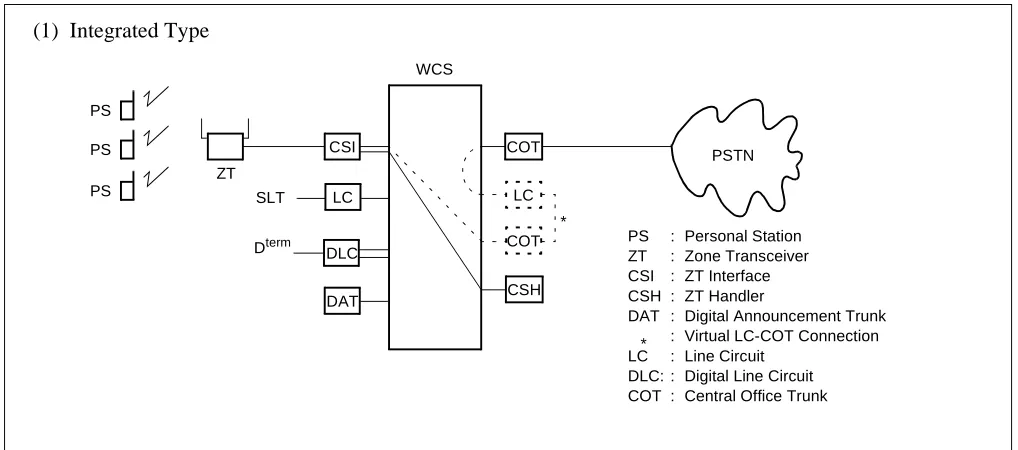
The wireless communication system (WCS) is interfaced with a Personal Station (PS) via a Zone Transceiver (ZT).
When installing the WCS, there are three types of systems:
1. Integrated Type
The NEAX2000 IVS/1000 IVS provides both PBX and WCS functions.
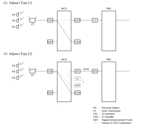
2. Adjunct Type [1]
The WCS is an adjunct system to the existing PBX linked by LC-COT connection.
3. Adjunct Type [2]
The WCS is an adjunct system to the existing PBX linked by CCIS.
Figure 2-1 shows the system diagram of the WCS.
Figure 2-1 System Diagram of WCS Integrated Type (1 of 2)
CSI COT
LC
DAT CSH
ZT SLT
PSTN PS
PS PS
WCS (1) Integrated Type
PS : Personal Station ZT : Zone Transceiver CSI : ZT Interface CSH : ZT Handler
DAT : Digital Announcement Trunk : Virtual LC-COT Connection LC : Line Circuit
DLC: : Digital Line Circuit COT : Central Office Trunk LC
COT *
Figure 2-1 System Diagram of WCS (2 of 2)
CSI COT
DAT CSH
ZT PS
PS PS
WCS
LC
PBX
CSI DTI
DAT CSH
ZT PS
PS PS
WCS
PS : Personal Station ZT : Zone Transceiver CSI : ZT Interface CSH : ZT Handler
DAT : Digital Announcement Trunk * : Virtual LC-COT Connection LC
COT * (2) Adjunct Type [1]
(3) Adjunct Type [2]
DTI
PBX
2.2 CSH
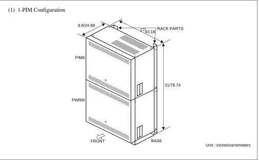
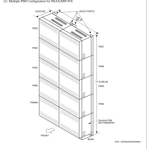
Examples of module configurations are shown in Figure 2-2.
Figure 2-2 Module Configurations (1 of 4) Note: For WCS application, ICSVS PIMN-UB is required for each PIM.
RACK PARTS
PWRM
BASE FRONT
17/ 9.8/24.89
31/78.74 PIM0
(1) 1-PIM Configuration
Figure 2-2 Module Configurations (2 of 4)
PIM7
PIM6
PIM4 PIM3
PIM2
PIM1
PIM0
FRONT
RACK PARTS
BASE PWRM
(2) Multiple PIM Configuration for NEAX2000 IVS
Dummy PIM/ BATTM/MDFM 34/
9.8/24.89
Unit : inches/centimeters PIM5
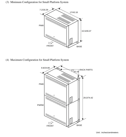
Figure 2-2 Module Configurations (3 of 4)
RACK PARTS
PWRM
BASE FRONT
17/ 9.8/24.89
29.3/74.42 PIM0
(4) Maximum Configuration for Small Platform System
Unit : inches/centimeters BASE
17/43.18 7.2/18.29
15.5/39.37 PIM0
(3) Minimum Configuration for Small Platform System
FRONT
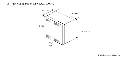
Figure 2-2 Module Configurations (4 of 4)
Unit : inches/centimeters 13.8/35.05
8.521.59
13.8/35.05 PIM0
(5) PIM Configuration for NEAX1000 IVS
2.3 Outline of Circuit Cards
Table 2-1 shows the functional outline of circuit cards used for WCS.
Table 2-1 Functional Outline of Circuit Card
CARD NAME FUNCTIONAL
NAME FUNCTIONAL OUTLINE
PN-SC03 CSH
ZT Handler card.
This card controls 4 CSI cards and is equipped with 8 circuits of D channel signalling interface.
PN-2CSIA CSI
ZT Interface card.
This card is used to interface with ZT, based on ISDN S-interface. Max. 2 ZTs can be connected with 1 CSI card.
PZ-PW91 PW91
-48 V power supply card for ZT.
A PW91 card provides -48V DC power for a maximum of 24 ZTs. Max. 4 cards per PWRM.
PZ-PW86 PW86
Main Power Supply card.
This card provides power to all circuit cards mounted in the PIM. 1 card per PIM.
PZ-PW00 PW00
Power Supply card for ZT.
This card provides -48 V DC power for a maximum of 2 ZTs and is mounted in the LT/AP slot of PIM. Max 3 cards per system.
PN-2DATA DAT
2-line Digital Announcement Trunk card.
This card is used for Announcement Service on the WCS. Recording time: Max. 60 seconds.
PN-4COTB COT
4-line Central Office Trunk card.
This card is used for Adjunct Type 1 (LC-COT connection). A 4 COT card is required per 4 PSs.
PN-24DTA DTI
24 Channel Digital Trunk Interface card.
This card accommodates 24 channel PCM digital line and is used for CCIS connection of Adjunct Type 2.
PN-30DTC DTI
30 Channel Digital Trunk Interface card.
This card accommodates 30 channel digital PCM line and is used for CCIS connection of Adjunct Type 2, or for Multi-Site Roaming connection be-tween the PBXs.
PN-SC00 CCH
Common Channel Handler card.
This card controls common signalling channels of No.7 CCIS and is used for CCIS connection of Adjunct Type 2.
PN-SC01 DCH
D-Channel Handler card.
Note: When the PWRU-A is equipped with the PZ-PW112 for NEAX1000 IVS, follow the following accommo-dation limitations.
• Max. five 8DLC cards
or
• Max. four 8DLC cards and two 4DIT cards.
PN-AP00-A DBM
Data Base Module card for Multi-Site Roaming. This card stores data related to Multi-Site Roaming.
1 card per system is required on each PBX in the network which provides Multi-Site Roaming.
PWRU-A
Note
–48V/50W DC/DC PWR
Power Supply Unit for ZT. (for NEAX1000 IVS only)
This unit provides –48V DC power for a maximum of 6 ZTs, and is mounted in the vacant space at the lower left side of a Main Power Supply card. 1 unit per PIM is available.
Table 2-1 Functional Outline of Circuit Card
CARD NAME FUNCTIONAL
3. SYSTEM SPECIFICATIONS
3.1 System Specifications
Table 2-2 System Specifications
DESCRIPTION SPECIFICATIONS REMARKS
Wireless Protocol
Based on second generation wireless telephone system standard RCR-STD-28 FCC Sub part D, UTAM complied
Distance between PBX and ZT
Note: At Nominal Voltage of -48V.
Interface with a PBX Analog station line interface For Adjunct Type [1]
TI or EI interface with CCIS For Adjunct Type [2]
WIRE DIAMETER 26 AWG 24 AWG 22 AWG
POWER SUPPLY WCS LOCAL WCS LOCAL WCS LOCAL
DISTANCE 1500 ft. (457 m)
2000 ft. (609 m)
2000 ft. (609 m)
3000 ft. (914 m)
3000 ft. (914 m)
3.2 System Capacity
Note 1: When Multi-Site Roaming is provided, “Number of PS” and “Number of simultaneous connections for PS” equal the sum of the Number of the Home PS and the Visitor PS.
Note 2: The capacity of the PSs can be expanded to the number in parentheses. For details, refer to next section. Table 2-3 NEAX2000 IVS WCS System Capacity
DESCRIPTION
CAPACITY
REMARKS Integrated Type
Adjunct Type Type1
(LC-COT)
Type2 (CCIS)
Number of PS Note 1 168
(250) Note 2 248
162
(232) Note 2
Number of simultaneous
connections for PS Note 1
152
(159) Note 2
219
(234) Note 2
146
(153) Note 2
Number of B channels per ZT (Simultaneous
connections per ZT)
3 3 3
Number of ZT 96 96 80
Number of ZT per CSI 2 2 2
Number of Calling Areas 32 32 32
Number of ZT per Calling
Area 96 96 80
Number of CSI 48 48 40
Max. 12 per PIM (No local power supplied)
Note 1: When Multi-Site Roaming is provided, “Number of PS” and “Number of simultaneous connections for PS” equal the sum of the Number of the Home PS and the Visitor PS.
Note 2: The capacity of the PSs can be expanded to the number in parentheses. For details, refer to next section. Table 2-4 Small Platform System WCS System Capacity
DESCRIPTION CAPACITY REMARKS Integrated Type Adjunct Type (LC-COT) (CCIS)
Number of PS
Note 1
Type 1 (PW00)
168
(250) Note 2
4COT: 32 8COT: 64
162
(232) Note 2
Type 2 (PW91)
168
(250) Note 2
4COT: 36 8COT: 64
162
(232) Note 2
Number of simultaneous connections for PS
Note 1
Type 1
(PW00) 18
4COT: 12
8COT: 16 18
Type 2
(PW91) 48
4COT: 24
8COT: 32 48
Number of B channel per ZT
(Simultaneous connections per ZT) 3 3 3
Number of ZT
Type 1
(PW00) 6 6 6
Type 2
(PW91) 16 16 16
Number of ZT per CSI 2 2 2
Calling Areas
Type 1
(PW00) 6 6 6
Type 2
(PW91) 16 16 16
ZT per Calling Area
Type 1
(PW00) 6 6 6
Type 2
(PW91) 16 16 16
Number of CSI
Type 1
(PW00) 3 3 3
Type 2
(PW91) 8 8 8
Number of CSH
Type 1
(PW00) 1 1 1
Type 2
*–48V power is provided to ZT by optional Local AC/DC power
Table 2-5 NEAX1000 IVS WCS System Capacity (1 PIM Configuration)
DESCRIPTION
CAPACITY Integrated Type
Adjunct Type
(LC-COT) (CCIS)
Number of PS
Note 1
Type 1 (PW00) 168
(250) Note 2
4COT: 16 8COT: 32
162
(232) Note 2
Type 2* (Local) 168
(250) Note 2
4COT: 24 8COT: 40
162
(232) Note 2
Type 3 (PWRU-A) 168
(250) Note 2
4COT: 24 8COT: 40
162
(232) Note 2
Number of simultaneous connections for PS
Note 1
Type 1 (PW00) 12 4COT: 6
8COT: 8 6
Type 2* (Local) 30 4COT: 16
8COT: 24 24
Type 3 (PWRU-A) 18 4COT: 16
8COT: 18 18
Number of B channel per ZT
(Simultaneous connections per ZT) 3 3 3
Number of ZT
Type 1 (PW00) 4 4 2
Type 2* (Local) 10 10 8
Type 3 (PWRU-A) 6 6 6
Number of ZT per CSI 2 2 2
Calling Areas
Type 1 (PW00) 4 4 2
Type 2* (Local) 10 10 8
Type 3 (PWRU-A) 6 6 6
ZT per Calling Area
Type 1 (PW00) 4 4 2
Type 2* (Local) 10 10 8
Type 3 (PWRU-A) 6 6 6
Number of CSI
Type 1 (PW00) 2 2 1
Type 2* (Local) 5 5 4
Type 3 (PWRU-A) 3 3 3
Number of CSH
Type 1 (PW00) 1 1 1
Type 2* (Local) 2 2 1
* –48V power is provided to ZT by optional Local AC/DC power.
Note 1: When Multi-Site Roaming is provided, “Number of PS” and “Number of simultaneous connections for PS” equal the sum of the Number of the Home PS and the Visitor PS.
Note 2: The capacity of the PSs can be expanded to the number in parentheses. For details, refer to next section. Table 2-6 NEAX1000 IVS WCS System Capacity (2 PIM Configuration)
DESCRIPTION
CAPACITY Integrated Type
Adjunct Type
(LC-COT) (CCIS)
Number of PS
Note 1
Type 1 (PW00) 168
(250) Note 2
4COT: 48 8COT: 80
162
(232) Note 2
Type 2* (Local) 168
(250) Note 2
4COT: 56 8COT: 88
162
(232) Note 2
Type 3 (PWRU-A) 168
(250) Note 2
4COT: 56 8COT: 88
162
(242) Note 2
Number of simultaneous connections for PS
Note 1
Type 1 (PW00) 24 4COT: 18
8COT: 24 24
Type 2* (Local) 72 4COT: 32
8COT: 40 66
Type 3 (PWRU-A) 36 4COT: 32
8COT: 36 36
Number of B channel per ZT
(Simultaneous connections per ZT) 3 3 3
Number of ZT
Type 1 (PW00) 8 8 8
Type 2* (Local) 24 24 22
Type 3 (PWRU-A) 12 12 12
Number of ZT per CSI 2 2 2
Calling Areas
Type 1 (PW00) 8 8 8
Type 2* (Local) 24 24 22
Type 3 (PWRU-A) 12 12 12
ZT per Calling Area
Type 1 (PW00) 8 8 8
Type 2* (Local) 24 24 22
Type 3 (PWRU-A) 12 12 12
Number of CSI
Type 1 (PW00) 4 4 4
Type 2* (Local) 12 12 11
Type 3 (PWRU-A) 6 6 6
Number of CSH
Type 1 (PW00) 1 1 1
Type 2* (Local) 3 3 3
3.3 Expanding PS Capacity
The maximum number of Wireless PS stations has been expanded from 168 to 250 when an Integrated type system is being used. Previously, each PS line reduced the capacity of CM10 by three ports [One port for CM1C and two ports for CM10 (one Virtual Trunk and one Virtual Station)]. With a CPXX-C card and 1900 Series Release 2 software, each PS line reduces the capacity of CM10 by only two ports. A new memory area has been added for CM1C and this command no longer impacts the memory capacity of CM10.
To perform backups of the new memory area (save and load), an updated version of MATWorX-32 (Version 2.6 or higher) with the “MP4” file extension type must be used. (MP4 = Areas 1-6).
To expand the system capacity for the PS, the CP00-C/CP03-C card and 1900 Series Release 2 or later MP program are required. The table below shows the MP program upgrading procedure.
1D21--Default is “None.” No PS-ID. Must be reassigned. 1D15--Default is “15.” Mode 1.
1D01--Default is “None.” No Subline.
1202--Default is “1515.” Service Restriction Class A/B. 1216--Default is “None.” Must be reassigned.
1D20--Download the PS’s. Must be executed.
Note: The Down does not need to be successful, but Command 1D20 must be executed.
The maximum number of PSs that can be added to the system depends on the number of existing PSs in the system before upgrading. The following number of ports are required to provide a PS.
Before system upgrade: 3 ports per PS (for the PS, the virtual LC and the virtual COT) After system upgrade: 2 ports per PS (for the virtual LC and the virtual COT)
UPGRADE FROM UPGRADE TO UPGRADING PROCEDURE
MP Program:
1900 Series or earlier
MP Card: CP00-B CP03
MP Program:
1900 Series Release 2 or later
MP Card: CP00-C CP03-C
(1) Save office data (MP 3 area) of CP00-B/CP03 by MAT.
(2) Exchange CP00-B/CP03 to the CP00-C/CP03-C. (3) Load 1900 Series Release 2 MP program to
CP00-C/CP03-C.
(4) Clear all office data by CM00 1st: 1, 2nd: CCC. (5) Load saved office data of CP00-B/CP03.
MP Program:
1900 Series or earlier
MP Card: CP00-C CP03-C
MP Program:
1900 Series Release 2 or later
MP Card: CP00-C CP03-C
(1) Load 1900 Series Release 2 MP program. (2) Clear office data for new memory area by CM00
The table below shows the example of the system capacity on NEAX2000 IVS.
Note: When the 168 PSs have been provided in the system, and more PSs are required, the all existing PSs’ office data must be cleared by the CM1C individually and re-entered. By this means, up to 250 PSs can be provided.
For example, if 50 PSs will be added, 100 existing PSs’ office data must be cleared and re-entered.
Existing 168 PSs 68 PSs (3 ports per PS)
100 PSs (2 ports per PS) Office data must be cleared and re-entered.
Adding PSs 50 PSs (2 ports per PS)
INSTALLING
CONDITION EXISTING PS ADDING PS CS D
term REQUIRED PORTS REMARKS
When upgrading a system
168 100 50
0 100 175
1 1 1
0 4 4
511 511 511
Note
When installing a new system
0 0
168 250
1 1
168 4
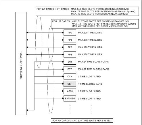
3.4 Time Slot Assignment Conditions 3.4.1 Time Slots for CSH Card
As shown in Figure 2-3, the CSH card uses the time slot on the same highway as the other application cards such
as [PN-AP00 (AP00)/PN-ME00 (EXTMEM)]. Therefore, the total number of time slots for all CSH card must be less than 128 time slots including all other application cards.
Figure 2-3 Accommodation of CSH into TDSW 3.4.2 Time Slots for CSI Card
CSH
AP00
EXTMEM
4 TIME SLOTS / CARD
1 TIME SLOT / CARD
1 TIME SLOT / CARD DTI
CCH 1 TIME SLOT / CARD
FOR L/T CARDS : MAX. 512 TIME SLOTS PER SYSTEM (NEAX2000 IVS)
FP1 FP0
FP2
FP3
T
D
SW
(1024 T
IME
S
L
O
T
S
)
MAX.128 TIME SLOTS
MAX.128 TIME SLOTS
MAX.128 TIME SLOTS
MAX.128 TIME SLOTS
FOR L/T CARDS + DTI CARDS : MAX. 512 TIME SLOTS PER SYSTEM (NEAX2000 IVS)
FOR AP CARDS : MAX. 128 TIME SLOTS PER SYSTEM MAX.24 TIME SLOTS / CARD
• • • •
• • • •
MAX. 72 TIME SLOTS PER SYSTEM (Small Platform System) MAX. 48 TIME SLOTS PER SYSTEM (NEAX1000 IVS)
MAX. 72 TIME SLOTS PER SYSTEM (Small Platform System) MAX. 48 TIME SLOTS PER SYSTEM (NEAX1000 IVS)
4. OUTLINE OF MULTI-SITE ROAMING
4.1 Functional Outline
The PBX supports the JT-Q931a protocol and JT-11582 for signaling at Q-reference point between PBXs on the private network. By supporting this protocol, the PSs can be used in any Calling Area on the private network.
Figure 2-4 Functional Outline of Multi-Site Roaming
PBX A PBX B
ZT ZT
PS PS
ROAMING When a PS roams over the adjoining PBX’s Calling Area;
When a PS roams over other Calling Area through the relaying office;
PBX A PBX B
ZT ZT
PS PS
ROAMING PBX C
ZT
Dp Channel Private Line
Dp Channel Private Line
Dp Channel Private Line
Note: Also to the relaying office (PBX C), the installation and the data assignment for Multi-Site Roaming are required.
(JT-Q931a)
4.2 Multi-Site Roaming System Configuration
1. System Configuration
The following figure shows the system configuration for Multi-Site Roaming.
HOME PBX
CSI
DBM PLO DTI CSH
DCH ZT
VIRTUAL LC
VIRTUAL TRK
VIRTUAL LC
VIRTUAL TRK
PUBLIC NETWORK
PS
PS
TRK
VISITOR PBX
CSI
DBM PLO DTI CSH
DCH
ZT VIRTUAL
LC
VIRTUAL TRK
VIRTUAL LC
VIRTUAL TRK
TRK
PS
PS Dp Channel Private Line
(JT-Q931-a)
2. Words definition for Multi-Site Roaming
Virtual LC: Virtual LC exists only on the system data, provided via non-hardware supported
LEN’s. The Virtual LC must be assigned by the system data programming for op-erating Home PSs and Visitor PSs used for Multi-Site Roaming, together with the Virtual TRK.
Virtual TRK: Virtual TRK (trunk) exists only on the system data, provided via non-hardware
supported LENs. The Virtual TRK must be assigned by the system data program-ming for operating Home PSs and Visitor PSs used for Multi-Site Roaprogram-ming, togeth-er with the Virtual LC.
Individual PS Number: Individual PS Number is assigned to a PS to identify the PS on the Roaming Net-work. It must be an unique number in the netNet-work.
Network ID Method: Network ID Method is one Method to operate Multi-Site Roaming. A Roaming PS
must have two SYS-ID on the Network ID Method. One is Main SYS-ID for Home PBX, and another is Network ID for Roaming Network. The Network ID is used to define whether the PS can operate under the control of PBXs on the Roaming Network. The network ID must be the same for all PBXs within the same network.
Visitor PBX: When a PS leaves control of a PBX to which it belongs originally, and is operating
in a zone of another PBX, the PBX is called “Visitor PBX”.
Visitor PS: When a PS leaves control of a PBX to which it belongs originally, and is operating
in a zone of another PBX, the PS is called “Visitor PS”.
Home PBX: Home PBX is a PBX to which a PS ordinarily belongs.
Home PBX ID: Home PBX ID is a unique number to identify the PBX on the Roaming Network.
Home PS: When a PS operates under control of a PBX to which the PS originally belongs, the
PS is called “Home PS”.
Roaming Number: Roaming Number is assigned to a Visitor PS temporarily, when the PS is roaming
to a Visitor PBX. The Actual Roaming Number is Virtual LC Station number as-signed as a Pilot Station of Station Hunting Group on the Visitor PBX.
HLR: Home Location Register. A database to store the location registration data of the
Home PS.
VLR: Visitor Location Register. A database to store the location registration data of the
4.3 Summary of Multi-Site Roaming System Operation
1. Location Registration of PS
a. In the zone of the Visitor PBX, the Visitor PS requests the Visitor PBX for location registration of its
own.
b. The Visitor PBX analyses the number sent from the Visitor PS, and detects the Home PBX of Visitor
PS.
c. The Visitor PBX inquires of the Home PBX about the profiles; various data which is assigned to the
PS for the operation as a Visitor PS.
d. The Home PBX analyses the number included with the inquiry, and detects whether the Visitor PS is
one of the Home PS of its own.
If the Visitor PS is detected as a PS which belongs to another PBX, the PBX forwards the inquiry to the corresponding route.
e. If the Visitor PS is detected as a Home PS, the Home PBX sends the Visitor PS profiles to the Visitor
PBX.
f. The Visitor PBX confirms the profiles sent from the Home PBX, and determines the Roaming Number
for the Visitor PS.
The actual Roaming Number is Virtual LC Station number assigned as a Pilot Station of Station Hunt-ing Group on the Visitor PBX.
g. The Visitor PBX registers the profile data of the Visitor PS to the VLR.
h. Then notifies the completion of registration to the Home PBX. The notification contains the Roaming
Number determined.
i. The Home PBX receives the notification, and stores the Roaming Number to the HLR.
VLR VISITOR PBX
HLR
(b) Interpreting Home PBX (c) Profiles inquiry
(e) Sending profiles
(g) Registration to VLR HOME PBX
(d) Analyse the inquiry
Q931a Digital Line
(a) Re
questin
g lo catio
n re
gistratio
n
(i) Registration to HLR (h) Notification completion of registration
2. Call Termination to Visitor PS
a. The Home PBX receives the call to a Home PS from another PBX.
b. The Home PBX refers the HLR information of the PS.
c. From the Roaming Number contained in the HLR information, the Home PBX detects whether the
Home PS is roaming.
d. The Home PBX inquires of the Visitor PBX about the call termination to the Visitor PS. The inquiry
contains the roaming data of the Visitor PS, such as Roaming Number and Individual PS Number.
e. The Visitor PBX analyses the Roaming Number, and refers to the VLR information of the Visitor PS
in accordance with the Individual PS Number.
f. The Visitor PBX confirms the VLR information.
g. The Visitor PBX terminates the call to the Visitor PS.
Figure 2-7 Call Termination System Operation
VLR VISITOR PBX
HLR (d) Call termination inquiry
(e) Referring VLR HOME PBX
Q931a Digital Line
(g) C
all T erm
inati on (b) Referring HLR
(a) C all fro
m an other
PBX
(c) Interpreting the location of the PS
(f) Confirming VLR
4.4 Multi-Site Roaming System Condition
1. Trunk
• Multi-Site Roaming can be executed only on trunk connection between PBXs based on JT-Q931a
pro-tocol.
• To each trunk route of JT-Q931a trunks, it can be specified whether Multi-Site Roaming is provided or
not.
• The JT-Q931a trunks can be used by Single Line Telephone stations and Dterm stations for originating
or receiving calls as same as common trunks.
2. Data Base Module
• An AP00 card for Data Base Module (DBM) is required per PBX.
The AP00 card can not be used as Billing Application Processor (for SMDR, MCI, PMS or Hotel/Mo-tel features).
• System data stored in the memory of the AP00 card can be saved, loaded and verified from a MAT.
(Memory Area No.:A, Memory Address: 00900-10870, File Extension: DMA)
• A Roaming network can consist of maximum 512 PBXs.
• Visitor Location Register (VLR) information for maximum 512 Visitor PSs can be recorded to a
sys-tem.
VLR information is the various information of Visitor PS and is made in the memory of AP00 on the Visitor PBX when the PS is roaming.
When the VLR information exceeds for more than 512 PSs, AP00 overwrites the oldest VLR informa-tion.
3. Home PS/Visitor PS
• To use the PSs for Multi-Site Roaming, the following must be assigned to the PSs.
- SYS-ID; SYS-ID of Home PBX.
- PS-ID; An unique number for identifying the PS.
- Individual PS Number; The same number with the Home PBX ID. - Extension Number; The same number with the Individual PS Number.
1. GENERAL
This chapter details the installation procedure to provide WCS functions to the PBX.
2. PRECAUTION IN HANDLING
The installer must wear the grounded wrist strap to protect the circuit card from static electricity, when handling cards, and the installer must engage in the work on a grounded conductive work surface.
Figure 3-1 Static Electricity Precautions (1 of 2)
CARD FRONT PBX
WRIST STRAP • WHEN PLUGGING/UNPLUGGING A CIRCUIT CARD
• WHEN HOLDING A CIRCUIT CARD
FRAME GROUND SCREW
CONNECT THE GROUND WIRE TO THE FRAME EARTH OF THE EQUIPMENT.
Figure 3-1 Static Electricity Precautions (2 of 2)
The mark shown below is attached to the sheet for the work in which circuit cards are handled. When engaging in such work, the installer must be careful not to cause damage by static electricity.
WEAR A WRIST STRAP AND PERFORM THE WORK ON A GROUNDED
CONDUCTIVE WORK SURFACE.
WHEN CARRYING A CIRCUIT CARD AROUND, KEEP THE CARD IN THE CONDUCTIVE POLYETHYLENE BAG. CONDUCTIVE
POLYETHYLENE BAG
CIRCUIT CARD
CIRCUIT CARD • WHEN SETTING SWITCHES ON A CIRCUIT CARD
• WHEN CARRYING A CIRCUIT CARD
ATTENTION
Contents Static Sensitive Handling
CARD FRONT PBX
NEVER TOUCH THE COMPONENTS OR SOLDERED SURFACE WITH BARE HANDS.
You must hold the card name label area, when plugging or unplugging the circuit card. If you touch another area, you may be exposed to hazardous voltages.
3. EQUIPMENT AND CABLES
Table 3-1 below shows the equipment required when providing the WCS interface to the system.
Table 3-1 Required Equipment for WCS
EQUIPMENT DESCRIPTION QUANTITY REMARKS
(1) For Integrated Type/Adjunct Type
• ICS VS PIMN-UB
- SN1273 PIMN-A
- PZ-PW86
- PWR CNT (CA-A)
- AC CORD-B-U
- RACK PARTS
Port Interface Module for WCS N N: 1-8
• POWER MODULE-UB
- SN1302 PWRMC-A
- PWR CNT CA-B
- RACK PARTS
- BATT BRACKET
ASSEM
- BATT CA-PSI
- AC CORD (A)
Power Module for PW91 card 1
• ICS VS BASE/TOP-UB
- SN1317 BASEG-A
- AC CORD (A)
Base unit and top cover N N: 1-2
• PZ-PW91 W/CA
- PZ-PW91
- PWR-1.7 CA-WA
- AC CORD-B-U1
- PWR CA-A
- 48V Power supply card for ZT N N: 1-4
• PN-PW00 - 48V Power supply card for ZT
(for Small Platform System/1000IVS)
N N: 1-3
• PWRU-A - 48V Power supply card for ZT
(for 1000IVS)
N N: 1-2
• PN-2CSIA ZT Interface card → 2 ZT/card N N: 1-48
• PN-SC03 8CSH (AP) ZT Handler card → 4 2CSIA/card N N: 1-12
• PN-2DATA (DAT) Digital Announcement Trunk N N: As required for
Announcement Service
When providing Roaming Service
• PN-24DTA-A/
30DTC/30DTC-A (DTI)
24/30 channels DTI card N N: 1-5
(2) For Adjunct Type [1]
The equipment above (1) except the PS are required with the following:
• PN-4COTB (COT) Central Office Trunk N N: Number of PS/4
• PS Personal Station N N: 1-248
(3) For Adjunct Type [2]
The equipment above (1) except the PS are required with the following:
• PN-24DTA-A/
30DTC/30DTC- (DTI)
24 channels DTI card N N: 1-5
• PN-SC00 (CCH) Common Channel Handler card N N: 1-4
• PS Personal Station N N: 1-162
Table 3-1 Required Equipment for WCS (Continued)
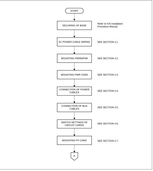
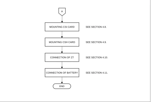
4. INSTALLATION PROCEDURE
Perform the installation of the equipment according to the procedure shown in Figure 3-2.
SEE SECTION 4.1.
SEE SECTION 4.2.
SEE SECTION 4.3.
SEE SECTION 4.4. START
SECURING OF BASE
MOUNTING PWRM/PIM
A
AC POWER CABLE WIRING
MOUNTING PWR CARD
CONNECTION OF POWER
MOUNTING FP CARD CABLES
CONNECTION OF BUS CABLES
SWITCH SETTINGS OF CIRCUIT CARDS
SEE SECTION 4.5.
SEE SECTION 4.6.
Figure 3-2 Installation Procedure (2 of 2)
SEE SECTION 4.8.
SEE SECTION 4.9.
END
MOUNTING CSI CARD
SEE SECTION 4.10. CONNECTION OF ZT
A
MOUNTING CSH CARD
4.1 AC Power Cable Wiring
STEP 1: Secure the BASE to the floor. For details, refer to the IVS Installation Procedure Manual.
STEP 2: Secure the AC CORD-B-U/AC CORD-B-U1 cables to the FG, NEUTRAL and LINE terminals on the BASE as shown in Figure 3-3 and 3-4.
Figure 3-3 Screwing AC CORD-B-U to Terminals Note: AC CORD - B - U ... to PW86 card in each PIM
AC CORD - B - U1 ... to PW91 card in Power Module
(PROVIDED WITH BASE) TO 120/240 V AC SOURCE POWER PUSH : INSERT THE AC CORD
PULL : FIXED THE AC CORD
CORD BUSH
(PROVIDED WITH BASE)
AC POWER KNOCK OUT HOLE
AC CO
RD -B-U
/U1 TO
PW
86 CAR
D IN PIM
/PIM
91 CAR
D
PIM
BASE
FG CABLE
(PROVIDED WITH BASE)
3P AC POWER CABLE SUPPLEMENTARY GROUND
Figure 3-4 Wiring AC CORD-B to Terminals
STEP 3: The AC CORD (A) and the FG Cable are pre-installed with the BASE.
WARNING: For configurations with 3 or more PIMs plus one Power Module, secure the additional AC CORD (A) to the BASE as shown in Figure 3-5.
AC CORD-B-U TO PW91 CARD IN PWRM
AC CORD-B-U TO PW86 CARD IN PIM
FG NEUTRAL LINE
BASE
Figure 3-5 Wiring AC CORD (A) to Terminals
FG NEUTRAL LINE
BASE
Additional AC CORD (A)
4.2 Mounting PWRM/PIM
STEP 4: Mount the PWRM on the BASE, and connect them together using three (3) bolts (provided) as shown in Figure 3-6.
Note: The PWRM must be mounted over the 4 RACK PART screws previously installed.
Figure 3-6 Mounting of PWRM
STEP 5: Mount and connect the PIM on the PWRM with three bolts provided.
When the system is a multiple-PIM configuration, connect PIMs to each other in the same manner.
Note: The Battery Module (BATTM) and/or the MDF Module (MDFM) can be installed in the same man-ner as the PWRM.
BASE
FRONT
4.3 Mounting PWR Card 4.3.1 Mounting PW91 Card
Mount the PW91 card into the Power Module (PWRM) as shown in Figure 3-7.
Figure 3-7 Mounting PW91 Card into PWRM (Power Module Unit)
PW91
4.3.2 Mounting PW00 Card
1. Small Platform System
Mount the PW00 card into the LT00-LT10 slot or AP5 slot. A maximum of three PW00 cards can be mounted in one PIM.
Figure 3-8 Mounting PW00 Card into PIM (1 of 2)
PW00
BUILT-IN BATTERY PIM
P W R
ATTENTION
Contents Static Sensitive Handling Precautions Required
Note: The PW00 card occupies the adjoining left side (smaller number) slot because of its two-stories structure.
LT
00
LT
01
LT
02
LT
03
LT
04
LT
05
LT
06/
AP
0
LT
07/
AP
1
LT
08/
AP
2
LT
09/
AP
3
LT
10/
AP
4
2. NEAX1000 IVS
Mount the PW00 card into the LT00-LT08 slot.
A maximum of three PW00 cards can be mounted in one PIM.
Figure 3-8 Mounting PW00 Card into PIM (2 of 2)
PW00
BUILT-IN BATTERY PIM
P W R
LT
00
LT
01
LT
02
LT
03
LT
04
/A
P
0
LT
05
/A
P
1
LT
06
/A
P
2
LT
07
/A
P
3
LT
08
/A
P
4
MP
ATTENTION
Contents Static Sensitive Handling Precautions Required
4.3.3 Mounting –48V PWR Unit to NEAX1000 IVS
STEP 1: Screw the –48V PWR unit on PWR MOUNT.
Figure 3-9 Fixing –48V PWR Unit to PWR MOUNT
PWR MOUNT –48V PWR UNIT
M3, 20 mm ATTENTION
STEP 2: Connect the PWR CA-WK to the –48V PWR unit.
Figure 3-10 Connecting PWR CA-WK
BLACK
BLUE
TO PWR0C
TO PWR0A
TO MAIN POWER SUPPLY CARD WHITE
RED BLACK
WHITE
M4, 5 mm
M4, 5 mm M3, 6 mm
M3-20mm
M3-20mm ATTENTION
Figure 3-11 PWR CA-WK
160 (6.3)
120 (4.7)
(15.7) 400
(3.9) 100
STEP 3: Secure the PWR MOUNT to the PIM by two screws.
Figure 3-12 Securing PWR MOUNT to PIM
ATTENTION
Contents Static Sensitive Handling Precautions Required
MAIN POWER SUPPLY CARD
PWR MOUNT
INSERT INTO THE SLITS ON
4.4 Connection of Power Cables 4.4.1 AC CORD
STEP 1: Connect the AC CORD-B-U to the PW86 and AC CORD-B-U1 to the PW91 card as shown in Figure
3-13.
Figure 3-13 Connection of AC CORD (1 of 2)
PW91
AC INPUT
AC INPUT Connector PW86
TO GROUND TERMINAL BWB PIM
PWRM
AC CORD-B-U
AC CORD-B-U
FG, NEUTRAL, LINE TERMINALS TO GROUND TERMINAL
Note: “AC INPUT connector” is not labeled on the PW86 card.
BASE
AC CORD (A)
Figure 3-13 Connection of AC CORD (2 of 2)
AC INPUT Connector PW86
BWB PIM
Note: “AC INPUT Connector” is not labeled on the PW86 card.
TO COMMERCIAL POWER
TO GROUND TERMINAL AC CORD-A-U
4.4.2 1-PIM Configuration
Connect the PWR-1.7 CA-WA cable and the PWR CNT CA-B cable as shown in Figure 3-14.
Figure 3-14 Connection of PWR-1.7 CA-WA and PWR CNT CA-B (For 1-PIM Configuration) (1 of 2)
SIG Connector
PW86 BWB (Back Wiring Board)
CARD SLOT AREA
LTC2 LTC1
LTC0 PWR0C
PWR1
RS PWR0B PWR0A PIM
PWRM
PWR-1.7CA-WA
PWR CNT CA-B
DCOUT
SIG
BATT2
BATT1 PW91
Note 1: “SIG Connector” is not labeled on the PW86 card.
Note 2: The PW86(D) card has Connector (CN103) in front of its panel.
SIG Connector
PW86 BWB (Back Wiring Board)
CARD SLOT AREA
LTC2 LTC1
LTC0 PWR0C
PWR0B PWR0A PIM
PWRM
PWR-1.7CA-WA
PWR CNT CA-B
DCOUT
SIG
BATT2
BATT1 PW91
Note 1: “SIG Connector” is not labeled on the PW86 card.
Note 2: The PW86(D) card has SIG Connector (CN103) in front of its panel.
PWR1
4.4.3 Multiple-PIM Configuration
STEP 1: Connect the PWR-1.7 CA-WA cable as shown in Figure 3-15 (Case 1).
Figure 3-15 Connection of PWR-1.7 CA-WA (For a Multiple PIM Configuration) (1 of 2)
PWR0C PWR0C
PWR0C PWR0C
PWR0C PWR0C
PWR0C PWR0C
PIM3
PIM2
PIM1
PIM0
PWRM
BASE
PIM7
PIM6
PIM5
PIM4
Dummy PIM/
BASE MDFM/BATTM
CABLE HOLE PWR0C
PW91 PW91
PW91 PW91
DCOUT DCOUT
DCOUT DCOUT
PWR-1.7 CA-WA
PWR-1.7 CA-WA PWR-1.7 CA-WA
PWR-1.7 CA-WA
STEP 1: Connect the PWR-1.7 CA-WA cable as shown in Figure 3-15 (2 of 2) (Case 2).
PWR0C PWR0C PWR0C
PWR0C PIM3
PIM2
PIM1
PIM0
PWRM
BASE
PW91 PW91
PW91 PW91
DCOUT DCOUT
DCOUT DCOUT
PWR-1.7 CA-WA
PWR-1.7 CA-WA
STEP 2: Connect the PWR CNT CA-A cable and the PWR CNT CA-B cable as shown in Figure 3-16.
Figure 3-16 Connection of PWR CNT CA-A and PWR CNT CA-B (For a Multiple PIM Configuration)
PWR1 PIM3
PIM2
PIM1
PIM0
PWRM
BASE
PIM7
PIM6
PIM5
PIM4
Dummy PIM/
BASE MDFM/BATTM PW91
PW91 PW91
PW91
SIG SIG
SIG SIG
PWR CNT CA-A PWR CNT CA-B
PW86
(SIG)
PWR1 PWR CNT CA-A
PW86
(SIG)
PWR1 PWR CNT CA-A
PW86
(SIG)
PWR1 PWR CNT CA-A
PW86
(SIG)
PWR1
PW86
(SIG) PWR1
PW86
(SIG) PWR1
PW86
(SIG) PWR1
PW86
(SIG)
PWR CNT CA-A PWR CNT CA-A PWR CNT CA-A
Note 1: “SIG Connector” is not labeled on the PW86 card.
Figure 3-17 PWR-1.7 CA-WA
Figure 3-18 PWR CNT CA-A
Figure 3-19 PWR CNT CA-B
400 mm (16 inch)
405 685 140 140 125
(16) (27) (5.5) (5.5) (5)
4.4.4 PW00 Card and PW86 Card Connection
Connect the PWR CA-WC cable, PWR CNT CA-A cable and the 4Q-TW-0.3 CONN CA cable as shown in
Figure 3-20. The 4Q-TW-0.3 CONN CA cable is used only when multiple PW00 cards are equipped.
Figure 3-20 Connection of PWR CA-WC/4Q-TW-0.3 CONN CA/PWR CNT CA-A Note 1: “SIG Connector” is not labeled on the PW86 card.
Note 2: The PW86(D) card has SIG connector (CN103) in front of its panel.
• Small Platform System/NEAX1000 IVS
MAIN POWER SUPPLY CARD
PIM
PWR CA-WC
PWR CNT CA-A 4Q-TW-0.3 CONN CA
SIG Connector PW00
PWR1 CONN Connector
4.4.5 PWR CNT CA-A and PWR CA-WK Connection
When the –48 PWR unit is eqiupped for NEAX1000 IVS, connect the PWR CNT CA-A cable and the PWR
CA-WK as shown in Figure 3-21.
Figure 3-21 Connection of PWR CNT CA-A and PWR CA-WK
MAIN POWER SUPPLY CARD BWB (Back Wiring Board)
PWR0C
PIM 0,1
PWR1
PWR0A
(SIG) CARD SLOTS
PWR CA-WK –48V PWR UNIT PWR CNT CA-A
4.5 Connection of BUS Cables
STEP 1: When the system is a multiple-PIM configuration, mount the BS00 card in the BUS slot of PIM0. Mount the BS01 card in each BUS slot of PIM1 through PIM7.
When the system is a single-PIM configuration, neither BS00 nor BS01 card is needed.
Figure 3-22 Mounting of BUS Cards
B S 0 1
B S 0 1
B S 0 1
B S 0 0
B S 0 1
B S 0 1
B S 0 1
B S 0 1 PIM3
PIM2
PIM1
PIM0
PIM7
PIM6
PIM5
STEP 2: When the system is a multiple-PIM configuration, connect all the BUS cards to each other using
BUS cables, as shown in Figure 3-23 and Figure 3-24.
Figure 3-23 BUS Cable
700 mm (27.6 inch)
Figure 3-24 Connection of BUS Cables
PIM7
PIM6
PIM5
PIM4 PIM3
PIM2
PIM1
PIM0
BS01
CN2 CN1
CN2 CN1
CN2 CN1
CN2
CN1
BS01
CN2 CN1
CN2 CN1
CN2 CN1
CN2 CN1
48-TW-0.7 CONN CA BS01
BS01
BS00
BS01
BS01
4.6 Switch Settings of Circuit Cards
Table 3-2 shows the circuit cards to be explained in this section.
* MB = Make Busy
For the other circuit cards, refer to the Circuit Card Manual.
Table 3-2 List of Circuit Cards
NAME
SWITCHES X: PROVIDED —: NOT PROVIDED
LAMPS X: PROVIDED —: NOT PROVIDED
EXTRACTION/INSERTION WITH POWER ON
X: ALLOWED ∆: ALLOWED AFTER MB*
—: NOT ALLOWED
REFERENCE
PW91 card X X — Section 4.6.1
PW00 card X X ∆ Section 4.6.2
CSH card X X ∆ Section 4.6.3
4.6.1 Switch Settings of PW91 Card
On the PW91 card, set the switches as shown in Figure 3-25 and Table 3-3.
Table 3-4 shows lamp indications on the PW91 card.
CAUTION
• When the operating power is being supplied to this circuit card, do not plug/unplug this circuit card into/from its mounting slot.
• Set the appropriate voltage by using the AC voltage select switch (slide switch) before powering on.
FRONT VIEW SIDE VIEW
SW ON
BAT OPE
OFF ON
240V AC 100/120V AC 1
2
PWR ALM
BATT2
BATT1
AC INPUT SIG MODE
The figure in the SWITCH NAME column and the position in in the SETTING POSITION column
indicate the standard setting of the switch. When the switch is not set as shown by the figure and , the
setting of the switch varies with the system concerned.
Table 3-3 Switch Settings on PW91 Card SWITCH NAME SWITCH
NUMBER
SETTING
POSITION FUNCTION CHECK
BAT OPE
PRESS MOMENTARILY
To start each PIM on battery power, when AC power is not provided (Switch “SW” must be ON).
MODE
1 Not used
2
Standard setting for equalize battery charg-ing (Set to equalize for Gel cell or no bat-tery. Typically 54.6V (52.7 ~ 56.5V))
OFF For float battery charging
Typically 51.6V (49.8 ~ 53.5V)
SW
ON For turning AC source power on
OFF For turning AC source power off
AC INPUT: 90 V - 138 V
DOWN AC INPUT: 180 V - 276 V
Table 3-4 Lamp Indications on PW91 Card
LAMP NAME COLOR FUNCTION
PWR ALM Red Lights upon occurrence of a major trouble
ON Green Remains lit while the operating power is being supplied
1
2 ON
OFF
ON
ON
OFF
100/120VAC
240VAC
4.6.2 Switch Settings of PW00 Card
On the PW00 card, set the switches as shown in Figure 3-26 and Table 3-5.
Table 3-6 shows lamp indications on the PW00 card.
Figure 3-26 Locations of Switches, Lamps and Connectors on PW00 Card
RUN
MB
The figure in the SWITCH NAME column and the position in in the SETTING POSITION column
indicate the standard setting of the switch. When the switch is not set as shown by the figure and , the
setting of the switch varies with the system concerned.
Note: When the power is on, flip the MB switch to ON (UP position) before plugging/unplugging the circuit card.
Table 3-5 Switch Settings on PW00 Card
SWITCH NAME SWITCH
NUMBER
SETTING
POSITION FUNCTION CHECK
MB (Toggle SW)
Note
UP For make-busy (–48 V power off)
For normal operation (–48 V power on)
Table 3-6 Lamp Indication on PW00 Card
LAMP NAME COLOR FUNCTION
RUN Green Remains lit while –48 V power is being supplied
ON
4.6.3 Switch Settings of CSH Card
On the CSH card, set the switches as shown in Figure 3-27 and Table 3-7.
Table 3-8 shows lamp indications on the CSH card.
Figure 3-27 Locations of Switches and Lamps on CSH Card
SENSE
RUN
MB
The figure in the SWITCH NAME column and the position in in the SETTING POSITION column
indicate the standard setting of the switch. When the switch is not set as shown by the figure and , the
setting of the switch varies with the system concerned.
Note 1: Set the groove on the switch knob to the intended switch position.
Note 2: When the power is on flip the MB switch to ON (UP position) before plugging/unplugging the circuit card.
Table 3-7 Switch Settings on CSH Card SWITCH
NAME
SWITCH NUMBER
SETTING
POSITION FUNCTION CHECK
SENSE (Rotary SW)
Note 1
4 ~ F Set the switch to match the AP Number (04 ~ 15) to be set by
CM05.
0 ~ 3 Not used
MB (Toggle SW)
Note 2
UP For make-busy
For normal operation
AP No. SW No.
10
04 05 06 07 08 09 11 12 13 14 15
4 5 6 7 8 9 A B C D E F
ON
Table 3-8 Lamp Indications on CSH Card
LAMP NAME COLOR FUNCTION
RUN Green Flashes at 120 IPM while the card is operating normally.
DOPE7 Green Lights when No.7 circuit D channel link is connected.
DOPE6 Green Lights when No.6 circuit D channel link is connected.
DOPE5 Green Lights when No.5 circuit D channel link is connected.
DOPE4 Green Lights when No.4 circuit D channel link is connected.
DOPE3 Green Lights when No.3 circuit D channel link is connected.
DOPE2 Green Lights when No.2 circuit D channel link is connected.
DOPE1 Green Lights when No.1 circuit D channel link is connected.
4.6.4 Switch Settings of CSI Card
On the CSI card, set the switches as shown in Figure 3-28 and Table 3-9.
Table 3-10 shows lamp indications on the CSI card.
Figure 3-28 Locations of Switches and Lamps on CSI Card
B03 B02 B01 B00 OPE
LB
B13 B12 B11 B10
DL1
The figure in the SWITCH NAME column and the position in in the SETTING POSITION column
indicate the standard setting of the switch. When the switch is not set as shown by the figure and , the
setting of the switch varies with the system concerned.
Note: Set the groove on the switch knob to the intended switch position. Table 3-9 Switch Settings on CSI Card SWITCH NAME SWITCH
NUMBER
SETTING
POSITION FUNCTION CHECK
DL0 (Rotary SW)
Note
0 ~ F
For normal operation
1 ~ F Not used
DL1 (Rotary SW)
Note
0 ~ F
For normal operation
1 ~ F Not used
0
Table 3-10 Lamp Indications on CSI Card
LAMP NAME COLOR FUNCTION
OPE Green Lights when the corresponding circuit is in use.
LB Red Lights when a loop-back is in progress.
B13 Red Not used (Flash [60IPM])
B12 Red
B channel status
ON : B2 channel of the No. 1 circuit is in use. OFF : B2 channel of the No. 1 circuit is in idle. Flash (60 IPM) : ZT is not connected to the No. 1 circuit.
ZT is in make-busy status.
B11 Red
B channel status
ON : B1 channel of the No. 1 circuit is in use. OFF : B1 channel of the No. 1 circuit is in idle. Flash (60 IPM) : ZT is not connected to the No. 1 circuit.
ZT is in make-busy status.
B10 Red
B channel status
ON : B0 channel of the No. 1 circuit is in use. OFF : B0 channel of the No. 1 circuit is in idle. Flash (60 IPM) : ZT is not connected to the No. 1 circuit.
B03 Red Not used (Flash [60 IPM])
B02 Red
B channel status
ON : B2 channel of the No. 0 circuit is in use. OFF : B2 channel of the No. 0 circuit is in idle. Flash (60 IPM) : ZT is not connected to the No. 0 circuit.
ZT is in make-busy status.
B01 Red
B channel status
ON : B1 channel of the No. 0 circuit is in use. OFF : B1 channel of the No. 0 circuit is in idle. Flash (60 IPM) : ZT is not connected to the No. 0 circuit.
ZT is in make-busy status.
B00 Red
B channel status
ON : B0 channel of the No. 0 circuit is in use. OFF : B0 channel of the No. 0 circuit is in idle. Flash (60 IPM) : ZT is not connected to the No. 0 circuit.
ZT is in make-busy status.
Table 3-10 Lamp Indications on CSI Card (Continued)
4.7 Mounting FP Card
Mount one FP (PN-CP01) card in the FP slot of PIM0 in any configuration. When the system is equipped with more than two PIMs – depending on the number of additional PIMs used – mount one FP card in the FP slot of PIM0 and one FP card in the MP/FP slot of PIM2, PIM4 and PIM6.
Figure 3-29 MP/FP Card Mounting Slots
PIM3 PIM7
PIM2 F PIM6
P F
P
PIM1 PIM5
PIM0 F PIM4
P M
4.8 Mounting CSI Card
Mount the CSI card in the LT slots of PIM0 through PIM7.
Figure 3-30 Mounting Location of CSI Card (1 of 3)
Note: The maximum number of four PIMs can be powered by PW91. (Figure 3-15). If a CSI card is remounted in a PIM that is not powered by PW91, an external AC/DC adapter can be used to power the ZT. A max-imum of 16 cards can be used; however, this number cannot be exceeded.)
BUILT-IN BATTERY
• Mount the CSI card in the LT slots (LT00-LT15) on PIM0-PIM7.
PIM
0 - 7 P
W R LT 00 LT 01 LT 02 LT 03 LT 04 LT 05 LT 06 LT 07 LT 08 LT 09 LT 10/ A P 0 LT 11/ A P 1 LT 12/ A P 2 LT 13/ A P 3 LT 14/ A P 4 LT 15/ A P 5 FP/ A P 6 MP /F P/ AP 7 BU S /AP 8 ATTENTION Contents Static Sensitive Handling Precautions Required
• NEAX2000 IVS
Figure 3-30 Mounting Location of CSI Card (2 of 3)
Note: When mounting 8 circuits LT card with cabling in the LT08 slot, the CSI card cannot be mounted in the LT09 slot.
CSI
CARD BUILT-IN BATTERY
• Mount the CSI card in the LT slots (LT00-LT09).
PIM
P W R
LT
00
LT
01
LT
02
LT
03
LT
04
LT
05
LT
06/
AP
0
LT
07/
AP
1
LT
08/
AP
2
LT
09/
AP
3
LT
10/
AP
4
AP
5
MP
ATTENTION
Contents Static Sensitive Handling Precautions Required
Figure 3-30 Mounting Location of CSI Card (3 of 3)
CSI
CARD BUILT-IN BATTERY
• Mount the CSI card in the LT slots (LT01-LT08).
PIM
P W R
LT
00
LT
01
LT
02
LT
03
LT
04/
AP
0
LT
05/
AP
1
LT
06/
AP
2
LT
07/
AP
3
LT
08/
AP
4
MP
ATTENTION
Contents Static Sensitive Handling Precautions Required